6, 291. 43, 583. 531, 252. 94, 607. 49, 392. N = 30. Total distance: Total outcome: κ. WI. WO. IO ...... Rossi, F. (2006). GNU Scientific Library Reference Manual.
FACULTEIT ECONOMIE EN BEDRIJFSWETENSCHAPPEN
KATHOLIEKE UNIVERSITEIT LEUVEN
APPOINTMENT-DRIVEN QUEUEING SYSTEMS
Proefschrift voorgedragen tot het behalen van de graad van Doctor in de Toegepaste Economische Wetenschappen door Stefan CREEMERS
Number 311
2009
Doctoral Committee
Advisor:
Prof. dr. Marc Lambrecht
Katholieke Universiteit Leuven
Members:
Prof. Prof. Prof. Prof.
Universiteit Antwerpen Katholieke Universiteit Leuven Katholieke Universiteit Leuven Katholieke Universiteit Leuven
dr. dr. dr. dr.
Benny Van Houdt Willy Herroelen Erik Demeulemeester Nico Vandaele
Daar de proefschriften in de reeks van de Faculteit Economie en Bedrijfswetenschappen het persoonlijk werk zijn van hun auteurs, zijn alleen deze laatsten daarvoor verantwoordelijk.
i
Dankwoord Het schrijven van een doctoraat wordt vaak vereenzelvigd met een heremitisch aangevat werk, louter ontsproten aan het brein van de doctorandus. Niets is minder waar. Voor de totstandkoming van dit werkstuk heb ik een veelheid aan mensen te danken . . . Een eerste woord van dank gaat uit naar mijn promotor en de leden van mijn doctoraatscommissie op wiens expertise ik meermaals beroep heb mogen doen. Prof. Dr. Marc Lambrecht heb ik leren kennen als een begiftigd lesgever en redenaar. Later heb ik ontdekt dat dit slechts enkele van zijn vele kwaliteiten zijn. Doorheen mijn jaren als doctorandus heb ik mogen ervaren dat Marc een correct, diplomatisch en vooral geduldig persoon is. Niet zelden heb ik zijn goede raad in de wind geslagen, enkel om te realiseren dat Marc het bij het rechte eind had. Vaak ook heb ik zijn geduld op de proef gesteld. De gemiste deadlines zijn niet langer op ´e´en hand te tellen. De parabel van de vlinder die van bloem tot bloem fladdert is me dan ook meermaals ter ore gekomen. Marc, dank u voor het vertrouwen en het geduld dat u in/met mij hebt gehad. Bedankt om me de kans te geven om dit doctoraat aan te vatten en met succes af te ronden. Prof. Dr. Erik Demeulemeester is een graag geziene gast op conferenties en ook binnen de faculteit heeft hij de nodige ambities aan de dag gelegd. Eriks parcours is vlekkeloos. Zijn capaciteiten in acht genomen, is dit evenwel niet zo verwonderlijk. Eriks analytisch vermogen en dan vooral de snelheid en de behendigheid waarmee hij dit vermogen hanteert, zijn angstwekkend. Dit werd al snel duidelijk tijdens het spelen van spelletjes en deelnames aan quizzen waarin Erik steevast de leiderstrui wist te bemachtigen. iii
Enkel bij het spelen van Jungle Speed was er sprake van een eerlijke competitie. Em. Prof. Dr. Willy Herroelen is zonder twijfel een boegbeeld, niet enkel binnen de onderzoeksgroep Productie & Logistiek maar ook binnen de faculteit en de universiteit zelf. Op gebied van projectplanning geniet Willy wereldfaam. Terecht. Zijn scherpe blik en onge¨evenaarde kennis van de literatuur zijn in staat om menig luchtbel te doorprikken (vaak op subtiele edoch hilarische wijze). Ik ben dankbaar voor alle conferenties die ik in het gezelschap van Willy heb mogen meemaken, zijn inzichten in de werking van het Belgische leger alsook zijn culinaire beslagenheid zullen me altijd bijblijven. Prof. Dr. Nico Vandaele heeft net zoals ik zijn sporen verdiend onder de hoede van Marc en heeft duidelijk diens praktische ingesteldheid ge¨erfd. Nico is een man die van vele markten thuis is. Hij combineert naadloos het gezinsleven met een academische en professionele carri`ere en slaagt er bovendien nog in om sportief aardige prestaties neer te zetten. Dit alles doet hij met de glimlach. Zijn organisatietalent alsook zijn gezonde levenshouding dwingen mijn respect af. Prof. Dr. Benny Van Houdt is een wereldautoriteit op het gebied van de wiskundige technieken die in dit doctoraat aan bod komen. Zijn sturing en zijn oog voor detail liggen aan de grondslag van het solide technische karakter van dit werkstuk. Doorheen onze samenwerking heb ik Benny zeer weten te appreci¨eren omwille van zijn sympathieke aanpak en zijn geduld met de wiskundig minder begaafde medemens. Ik betreur het nog steeds dat we niet de kans hebben gehad om samen een conferentie mee te pikken. Mijn dank gaat ook uit naar mijn collega’s die van mijn doctoraatsjaren vooral een hele fijne tijd hebben gemaakt. Nostalgie overvalt me wanneer ik terugdenk aan de vele avonden op caf´e, de conferenties, de beleefde avonturen . . . Bijzonder erkentelijk ben ik al degenen die met mij het bureau hebben gedeeld. Hiervan was Stijn de eerste en hij is voorlopig ook de laatste. Ik zou hem willen danken voor zijn goede raad, zijn ondersteuning, zijn vertrouwen en zijn vriendschap. Het is goed weten dat er steeds een donkere Leffe voor me klaar staat ten huize Van de Vonder. Na mijn verbanning naar iv
het “vijfde”, werd Damien mijn vaste stekgenoot. Menig hilarisch moment hebben we samen beleefd. Ik denk hierbij spontaan aan de fruit-shop, de broodjeskwestie en een niet nader benoemde cantus. De volgende in het rijtje was Stijn De Nijs. Hij leerde me dat ik beter had ge¨ınvesteerd in whisky in plaats van te beleggen op de beurs. Last but not least is er Filip die thans Stijn en mezelf vergezelt in een nieuw avontuur. Filip heb ik leren kennen als de verpersoonlijking van het spreekwoord “streng maar rechtvaardig”. Daarnaast herinner ik me natuurlijk ook de zelfgetapte pinten in de blokhut, mislukte kampeersessies en geanimeerde spelavondjes. Van de collega’s waarvan ik het betreur nooit hun kantoorgenoot te zijn geweest, is Olivier ´e´en van de eersten die in me opkomt. Van de vele talenten die Olivier rijk is, waardeer ik zijn talent voor humor nog het meest. Daarnaast is er natuurlijk ook Roel, met wie ik sinds jaar en dag een vruchtbare samenwerking onderhoud. Wat ooit begon op de stranden van Puerto Rico is thans uitgegroeid tot bekroond onderzoek dat wereldwijd werd gepresenteerd. Bedankt voor de vele avondjes uit, het dakterras in Istanbul, de waterpijp in Singapore & all that is yet to come! Onmisbaar in dit lijstje zijn ook mijn vaste ORAHS-mates. Ridder Georoen heeft eervol gestreden om mij te behoeden van verbanning van het Rode Ridder forum. Tevergeefs. Zijn sympathiek karakter en charmante na¨ıviteit hebben ervoor gezorgd dat Jeroen meermaals slachtoffer werd van practical jokes. Waarvoor dank. Brecht is een waar toonbeeld van rust en stabiliteit. Zijn nuchtere kijk op de werkelijkheid en diens achterliggende dynamiek heeft meer dan eens verhelderend gewerkt. Ik hoop van harte dat de ORAHS-traditie zich moge verder zetten. Robert was mijn voorganger als doctoraatsstudent bij Marc. Hij maakte me wegwijs in onderzoeksland en ver daarbuiten. Met veel plezier denk ik terug aan de vele beer games die we samen hebben gespeeld. Thans is het mijn beurt om Pieter te begeleiden in de wondere wereld van het onderzoek. Een taak die ik met veel genoegen op me neem. In reeds lang vervlogen dagen werd het HOG nog bevolkt door karakters zoals ene Kristof en ene Roselinde. Bling bling Kristof heb ik altijd weten te appreci¨eren omwille van zijn bereidwilligheid tot het nuttigen van een pint en het uithalen van een grap. Roselinde ben ik dankbaar voor het opfleuren van menig dag aan het HOG. The same could be said of Lu, who has proven v
to be a most fascinating conversation partner. Rabauw Ronny, 3zi voor de Wolfenstein-vrienden, wens ik succes bij het zoeken naar een verklaring voor mijn teencheat. Jade tot slot, zou ik willen bedanken voor haar aangename gezelschap. Moge je de horizonten vinden waarnaar je op zoek bent. Voorts draag ik goede herinneringen mee aan de overige leden van onze onderzoeksgroep alsook aan de mensen van ORSTAT; in het bijzonder Koen, Sofie, Fabrice en Lotte. The guys and girls van Marketing alsook Kristel, Lieve, Kurt, Rosanne en Lotte verdienen een bijzondere vermelding. Mijn vrienden hebben me de afgelopen jaren de mogelijkheid gegeven om mijn gedachten te verzetten wanneer dit nodig was. In mijn Heimat heb ik steeds kunnen rekenen op Rufus, Bertje, Bene en Raf. In het Bilzense gaat mijn dank uit naar mijn oude studiekameraden Dirk en Rabi alsook naar de bende van de paperclip (in het bijzonder Bernd, Dennis, Dominique, Fr´e, Johny, Tom en Yves). De wekelijkse retro en ladruppel in het gezelschap van Jan, Allaart en Arnaut, maakten menig middag tot een feest. Voor de supply van warez allerhande kon ik steeds terecht bij Bigbee, Kristof, Tim en Yves. Mijn kennis van het West-Vlaams dank ik dan weer aan Bram en Steven. Lies, Bart, Karel, Moenzie en Cindy horen ook in dit rijtje thuis. Verder ben ik zeer verplicht aan de familie Verelst, voor de kaartavondjes, de feestjes en zoveel meer. Tot slot een speciaal woord van dank voor An, die vaak het beste in mij wist boven te halen. Ik wens haar succes in alles wat ze onderneemt. De families Creemers, Praet en alle verwanten verdienen zeker een plaats in dit dankwoord. Veel te danken heb ik aan Mark, zijn vrouw Sofie en hun twee duivels Quinten en Wiene. Danke ook jp, wat had ik ervoor over gehad opdat je het licht van deze dag kon zien . . . . Moe had ik graag bedankt voor de vele zorgeloze zomervakanties. Tot slot resten nog mijn ouders. Zonder hen zou niets van dit alles mogelijk zijn geweest. Bedankt!
Stefan Creemers Leuven, Juni 15, 2008
vi
Abstract Many service and manufacturing systems are appointment-driven. In such systems, customers (e.g. patients, production orders, transportation vehicles, . . . ) make an appointment in order to receive service during some upcoming service session. Often, these appointments are made during socalled “arrival sessions” (e.g. during the opening hours of a hospital). After making an appointment, a customer is assigned an appointment date and joins an external queue referred to as the “waiting list”. Upon the appointment date, the customer leaves the waiting list and arrives at the service facility (e.g. a hospital). At the service facility, the customer is either served immediately or has to queue in order to receive service (i.e. the customer joins an internal queue). Often appointment-driven systems are characterized by a chronic backlog of customers to be served. The long waiting times involved and the inherent stochastic nature of the service process itself, result in reneging behavior, staff overtime, inefficient use of resources and missed company profits. The root of these problems may be found in a mismatch between capacity and demand. The main objective of this dissertation is to assess and optimize the trade-off between capacity and demand in appointment-driven systems. For this purpose, we develop a number of queueing systems: • The Service Allocation Model (SAM) assigns arriving customers an appointment date during one of the upcoming service sessions (i.e. the SAM allocates service capacity to arriving customers). The SAM is a general, complex vacation model that adopts matrix analytical methods and efficient algorithms in order to obtain numerically exact results on various performance measures. vii
• The Customer Appointment System (CAS) deals with the operational issue of scheduling the arrival of customers at the service facility during a particular service session. The CAS is modeled as a discrete-time Markov chain and adopts efficient algorithms in order to approximate system performance. The accuracy, validity and computational performance of both models are verified and compared using simulation studies. In addition, we perform extensive experiments as to obtain a deeper insight in the dynamics at work. Both models provide a valid contribution to the literature on vacation models and the literature on appointment systems (AS) respectively. Together, SAM and CAS may be linked in order to assess and optimize appointmentdriven systems as a whole. The analysis of appointment-driven systems as a whole has not yet been addressed in the literature. The analysis of appointment-driven systems yields four measures of interest: (1) customer waiting time at the waiting list; (2) customer waiting time at the service facility; (3) server idle time; (4) server overtime. Together, these performance measures may serve as the input of an optimization procedure capable of answering strategically important issues concerning server capacity (e.g. how often should a server be online, when should it be online, how many customers should be served during each service session, . . . ).
viii
Samenvatting Zowel in de diensten- als in de industri¨ele sector wordt veelvuldig gebruik gemaakt van afspraaksystemen om processen in goede banen te leiden. In zulke systemen maken cli¨enten (bijv. pati¨enten, productieorders, voertuigen, . . . ) een afspraak om een “service” te verkrijgen gedurende een zekere “servicesessie”. Vaak worden deze afspraken gemaakt tijdens zogenoemde “aankomstsessies” (bijv. gedurende de openingsuren van een ziekenhuis). Na het maken van een afspraak, wordt de cli¨ent een afspraakdatum toegewezen (i.e. de datum waarop de service zal worden ontvangen) en zal de cli¨ent een externe wachtrij vervoegen. Deze externe wachtrij staat ook wel bekend als de “wachtlijst”. Eenmaal de afgesproken datum aanbreekt, zal de cli¨ent de wachtlijst verlaten en zal de cli¨ent zich naar de servicelocatie begeven (bijv. het ziekenhuis). De cli¨ent wordt ofwel onmiddellijk bediend ofwel dient de cli¨ent te wachten tot de “server” (bijv. de dokter) beschikbaar is om de service toe te dienen (m.a.w. de cli¨ent vervoegt een interne wachtrij). Afspraakgedreven systemen worden vaak gekenmerkt door een chronische achterstand aan te verwerken cli¨enten. De lange wachttijden die hiermee gepaard gaan, alsmede het stochastische karakter van het serviceproces zelf, leiden tot het niet opdagen van cli¨enten, het verrichten van overuren door de server, het ineffici¨ent gebruik van hulpmiddelen en het daaruitvolgend mislopen van bedrijfsopbrengsten. De oorzaak van deze problemen dient gezocht te worden in de mismatch tussen vraag en capaciteit. Het hoofddoel van deze thesis is dan ook het afwegen en het optimaliseren van de trade-off tussen vraag en capaciteit in afspraakgedreven systemen. Hiertoe ontwikkelen we een aantal wachtlijnmodellen: • Het Service Allocatie Model (SAM) voorziet cli¨enten van een afspraakix
datum gedurende ´e´en van de opkomende servicesessies (m.a.w. het SAM alloceert capaciteit aan cli¨enten die een afspraak maken). Het SAM is een algemeen toepasbaar, complex “vacation model” dat gebruik maakt van matrix analytische technieken en effici¨ente algoritmes om numeriek exacte resultaten te bekomen van een aantal performantiemaatstaven. • Het Cli¨enten Afspraak Systeem (CAS) houdt zich bezig met het operationele vraagstuk om cli¨enten in te plannen in een servicesessie. Het CAS wordt gemodelleerd als een discrete-time Markov chain en maakt gebruik van effici¨ente algoritmes om de performantiemaatstaven van het systeem te benaderen. De accuraatheid, de validiteit alsook de computationele performantie van beide wachtlijnmodellen wordt geverifieerd en vergeleken door middel van simulatiestudies. Daarenboven wordt een aantal uitgebreide experimenten uitgevoerd om een dieper inzicht te verkrijgen in de gangbare dynamieken. Beide wachtlijnmodellen vormen een waardevolle bijdrage aan de relevante literatuur terzake (respectievelijk de literatuur met betrekking tot vacation models en de literatuur met betrekking tot afspraaksystemen). Gezamenlijk kunnen het SAM en het CAS worden gebruikt om een afspraakgedreven systeem in zijn geheel te bestuderen en te optimaliseren. De analyse van zulke systemen is een onderwerp dat tot op heden niet werd geadresseerd in de wetenschappelijke literatuur. De analyse van afspraakgedreven systemen levert ons de volgende performantiemaatstaven: (1) de wachttijd van de cli¨ent in de wachtlijst; (2) de wachttijd van de cli¨ent bij de server zelf; (3) de onbenutte tijd van een server; (4) het aantal overuren dat door de server wordt verricht. Deze performantiemaatstaven doen dienst als de input van een optimalisatieprocedure die ons in staat stelt om strategisch belangrijke kwesties inzake capaciteitsbenutting te beantwoorden (bijv. hoe vaak moet een server actief zijn, wanneer moet een server actief zijn, hoeveel cli¨enten moet een server verwerken gedurende een servicesessie, . . . ).
x
Contents Doctoral Committee
i
Dankwoord
iii
Abstract
vii
Samenvatting
ix
Table of contents
xi
1 Introduction 1.1 Practical relevance . . . . . . . . . . . . . . . . . . . . 1.2 Modeling approach . . . . . . . . . . . . . . . . . . . . 1.2.1 SAM . . . . . . . . . . . . . . . . . . . . . . . . 1.2.2 CAS . . . . . . . . . . . . . . . . . . . . . . . . 1.2.3 The link between the SAM and the CAS . . . . 1.2.4 Optimization of an appointment-driven system 1.3 Literature review . . . . . . . . . . . . . . . . . . . . . 1.3.1 Vacation models . . . . . . . . . . . . . . . . . 1.3.2 Appointment systems . . . . . . . . . . . . . . 1.4 Thesis outline . . . . . . . . . . . . . . . . . . . . . . .
. . . . . . . . . .
1 3 6 6 10 14 16 19 19 21 23
. . . .
25 25 25 28 30
2 Service Allocation Model 2.1 Definitions . . . . . . . . . . . . . 2.1.1 Basic Processes . . . . . . 2.1.2 Phase-Type Distributions 2.1.3 Counting process . . . . . xi
. . . .
. . . .
. . . .
. . . .
. . . .
. . . .
. . . .
. . . .
. . . .
. . . .
. . . .
. . . .
. . . . . . . . . .
. . . .
. . . . . . . . . .
. . . .
. . . . . . . . . .
. . . .
Contents
2.2
2.3
Model . . . . . . . . . . . . . . . . . . . . . . . . . . . . . . . 2.2.1 The DTMC Xj . . . . . . . . . . . . . . . . . . . . . . 2.2.1.1 A Classification of Vacations . . . . . . . . . 2.2.1.2 Algorithm . . . . . . . . . . . . . . . . . . . 2.2.1.3 Stationary distribution of the DTMC Xj . . 2.2.1.4 Expected number of customers in queue during a vacation of type j . . . . . . . . . . . . 2.2.1.5 Alternative computation of the stationary distribution of the DTMC Xj . . . . . . . . . . 2.2.2 Aggregation of results . . . . . . . . . . . . . . . . . . Experiments and results . . . . . . . . . . . . . . . . . . . . . 2.3.1 Model validity, accuracy and computational performance . . . . . . . . . . . . . . . . . . . . . . . . . . . 2.3.2 Numerical example . . . . . . . . . . . . . . . . . . . .
32 34 35 39 42 46 47 48 50 50 53
3 Customer Appointment System 55 3.1 Definitions . . . . . . . . . . . . . . . . . . . . . . . . . . . . . 55 3.1.1 Classification of appointment scheduling rules . . . . . 56 3.1.2 Basic processes . . . . . . . . . . . . . . . . . . . . . . 59 3.1.3 Discretization . . . . . . . . . . . . . . . . . . . . . . . 62 3.2 Model . . . . . . . . . . . . . . . . . . . . . . . . . . . . . . . 65 3.2.1 Transitions . . . . . . . . . . . . . . . . . . . . . . . . 65 3.2.2 Performance measures . . . . . . . . . . . . . . . . . . 69 3.2.3 Algorithm . . . . . . . . . . . . . . . . . . . . . . . . . 73 3.2.4 Implementation . . . . . . . . . . . . . . . . . . . . . . 75 3.3 Model extensions . . . . . . . . . . . . . . . . . . . . . . . . . 76 3.3.1 Delayed start of a service session . . . . . . . . . . . . 77 3.3.2 Interrupts of the service process . . . . . . . . . . . . 78 3.3.2.1 Preemptive interrupts of the service process . 79 3.3.2.2 Non-preemptive interrupts of the service process . . . . . . . . . . . . . . . . . . . . . . . 81 3.3.3 Model adaptations . . . . . . . . . . . . . . . . . . . . 82 3.3.3.1 Performance measures . . . . . . . . . . . . . 84 3.3.3.2 Algorithm . . . . . . . . . . . . . . . . . . . 86 3.4 Experiments and results . . . . . . . . . . . . . . . . . . . . . 86 xii
CONTENTS
3.4.1 3.4.2
3.4.3
3.4.4
3.5
Model validity, accuracy and computational performance . . . . . . . . . . . . . . . . . . . . . . . . . . .
89
Establishing the efficient frontier and the computation of frontier distance . . . . . . . . . . . . . . . . . . . .
92
3.4.2.1
Establishing the efficient frontier . . . . . . .
93
3.4.2.2
Computing the minimum distance towards the efficient frontier . . . . . . . . . . . . . .
95
Assessing appointment scheduling rule performance
.
97
3.4.3.1
General insights . . . . . . . . . . . . . . . .
97
3.4.3.2
Experimental design . . . . . . . . . . . . . .
99
3.4.3.3
Rule dominance (frontier membership) . . . 100
3.4.3.4
Distance towards the efficient frontier . . . . 106
3.4.3.5
Performance measure outcomes . . . . . . . . 117
3.4.3.6
General conclusions . . . . . . . . . . . . . . 121
Identification and evaluation of a set of “good” appointment scheduling rules . . . . . . . . . . . . . . . 122 3.4.4.1
Selection of the set of “good” appointment scheduling rules . . . . . . . . . . . . . . . . 122
3.4.4.2
Testing the set in various environmental settings . . . . . . . . . . . . . . . . . . . . . . . 128
Numerical example . . . . . . . . . . . . . . . . . . . . . . . . 135
4 Appointment-driven system
141
4.1
Model . . . . . . . . . . . . . . . . . . . . . . . . . . . . . . . 141
4.2
Experiments and results . . . . . . . . . . . . . . . . . . . . . 143 4.2.1
Experimental setting . . . . . . . . . . . . . . . . . . . 143
4.2.2
Dynamics of the waiting list . . . . . . . . . . . . . . . 144
4.2.3
Performance pairs . . . . . . . . . . . . . . . . . . . . 150
4.2.4
Evaluation of appointment scheduling rules . . . . . . 152 4.2.4.1
Effect of system utilization and interarrival time variability . . . . . . . . . . . . . . . . . 152
4.2.4.2
Effect of customer no-show and service session setup . . . . . . . . . . . . . . . . . . . . 160 xiii
Contents
4.2.4.3
4.3
Effect of variability in the service process and the arrival process of customers at the service facility . . . . . . . . . . . . . . . . . 162 4.2.4.4 Best performing appointment scheduling rules164 Numerical example . . . . . . . . . . . . . . . . . . . . . . . . 166
5 Conclusions 5.1 Conclusions chapter 1 . . . . 5.2 Conclusions chapter 2 . . . . 5.3 Conclusions chapter 3 . . . . 5.4 Conclusions chapter 4 . . . . 5.5 Directions for future research
. . . . .
. . . . .
. . . . .
. . . . .
. . . . .
. . . . .
. . . . .
. . . . .
. . . . .
. . . . .
. . . . .
. . . . .
. . . . .
. . . . .
. . . . .
. . . . .
. . . . .
173 . 173 . 174 . 174 . 176 . 177
A Markov chains 179 A.1 Discrete-time Markov chains . . . . . . . . . . . . . . . . . . . 179 A.2 Continuous-time Markov chains . . . . . . . . . . . . . . . . . 180 A.3 Example: Simplified SAM . . . . . . . . . . . . . . . . . . . . 181 List of Figures
185
List of Tables
189
Bibliography
191
Doctoral Dissertations from the Faculty of Business and Economics 203
xiv
CONTENTS
void
xv
Chapter 1
Introduction Many service systems require customers to make an appointment prior to receiving service. Often, these appointments are made during so-called “arrival sessions” (e.g. during office hours). After making an appointment, customers are issued an appointment date (which takes place at some future “service session”) and join an external queue which is referred to as the “waiting list”. Upon the appointment date, the customer is removed from the waiting list and receives service at the “service facility” (e.g. a doctors office). The arrival and service process of a customer at the service facility are subject to various “environmental variables” (e.g. interrupts during the service process, customer unpunctuality, . . . ). We refer to these systems as appointment-driven systems. They may be found in health care, legal services, administration and many other service and manufacturing industries. Often appointment-driven systems are characterized by a chronic backlog of customers to be served. The long waiting times involved and the inherent stochastic nature of the service process itself, result in reneging behavior, staff overtime, inefficient use of resources and missed company profits. The root of these problems may be found in a mismatch between capacity and demand. The main objective of this dissertation is to assess and optimize the trade-off between capacity and demand in appointment-driven systems. For this purpose we develop a number of queueing models. Appointment-driven systems are in fact a combination of two distinct queueing systems. In a first queueing system, customers make an appoint1
ment (i.e. arrive at the system), join the waiting list (i.e. are introduced in a queue) and leave the system at the start of the service session in which their service is administered. A second queueing system observes the queueing behavior of customers during the service session itself; it deals with the operational issue of scheduling a number of customers as to optimize some set of performance measures (e.g. server overtime, customer waiting time at the service facility, . . . ). We refer to both queueing systems as the Service Allocation Model (SAM) and the Customer Appointment System (CAS) respectively. Together, they may be used to analyze appointment-driven systems as a whole. The analysis of the appointment-driven system yields four measures of interest: (1) the waiting time of a customer at the waiting list; (2) the waiting time of a customer at the service facility; (3) the amount of time a server resides in an idle state; (4) the amount of overtime a server performs. Using these performance measures, strategically important issues concerning server capacity are addressed (e.g. how often should a server be online, when should it be online, how many customers should be served, . . . ). In the upcoming account we limit ourselves to the analysis of the expected values of these performance measures; remark however that the SAM and CAS allow the assessment of higher moments as well. The main contributions of this dissertation may be summarized as follows: (1) the development of a new queueing model to analyze the dynamics of the waiting list; (2) the development of a new queueing model to assess and optimize the performance of appointment systems; (3) establishing the link between both models in order to assess and optimize performance of appointment-driven systems as a whole. This introductory chapter is organized as follows. Section 1.1 motivates the practical relevance of the research objective. An intuitive outline of the modeling approach and the optimization problem involved is presented in Section 1.2. Section 1.3 reviews the relevant literature and Section 1.4 provides an outline of this dissertation. 2
CHAPTER 1. INTRODUCTION
1.1
Practical relevance
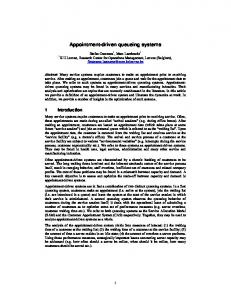
The relevance of this dissertation follows from its main research objective: the assessment and the optimization of performance in appointment-driven systems. Performance is measured in terms of: (1) customer waiting time at the the waiting list; (2) customer waiting time at the service facility; (3) server idle time; (4) server overtime. Optimizing and even assessing the size of the waiting list is a key strategic issue in many service and manufacturing industries (the size of the waiting list may be determined as a function of the waiting time of a customer at the waiting list). Waiting lists act as a rationing device to control the distribution of a limited amount of resources [8, 34, 44, 46, 48, 59, 65, 79, 80, 90, 112]. They grow until the point at which customers are no more willing to wait and start looking for alternatives (or withdraw altogether). This reneging behavior is counterpoised by a supply-induced demand (i.e. increasing the supply results in an increase in demand as well) [11, 16, 34, 35, 37, 38, 59, 65, 87, 90, 111]. Therefore, the reduction of the size of the waiting list increases: (1) customer throughput rate; (2) customer turnover rate ; (3) general profitability of the service provider. Optimization of appointment systems (i.e. identifying the scheduled arrival times of customers as to minimize: (1) customer waiting time at the service facility; (2) server idle time; (3) server overtime) is another key strategic issue. One can hardly underestimate the impact of server idle time and server overtime on system performance [10, 19, 22–24, 39, 103, 113]. With respect to customer waiting time at the service facility, various studies have shown its detrimental effect on customer satisfaction and the (perceived) quality of service [27, 103]. For instance, a recent study assessing the hospital experience of US patients [51] indicates that 41 % decide their choice of hospital based on nonclinical factors (e.g. waiting times, ease of making an appointment, . . . ). In addition, 75 % of patients have indicated the willingness to switch hospitals based on the timely conduction of scheduled appointments. Appointment-driven systems arise in almost every major industry (e.g. transportation, manufacturing, services, . . . ). They are most visible in the health care sector. This multi-trillion dollar industry, riddled with delays 3
1.1. Practical relevance
[37], devours large amounts of government, corporate and family budgets worldwide. According to the National Coalition on Health Care (NCHC), health care expenditures in the United States amounted to $2.4 trillion in 2008 (16.8% of the GDP; 4.3 times the amount spent on national defense) and is expected to increase to $4.3 trillion in 2017. Recently released figures present the statistics on health care expenditure as a share of GDP in 2005 for all OECD member countries [75]. The data are summarized in Figure 1.1. With average expenditures amounting to 8.96 percent of the GDP (in OECD member countries, in 2005), the health care sector may rightfully contend for the title of largest consumer of GDP. While abundant examples of appointment-driven systems may be found in services, their application in other industries is perhaps less apparent. The following listing illustrates some of these less apparent applications: • In manufacturing settings, the translation of a variable demand into a production schedule is an application of an appointment-driven system. Incoming orders are assigned a production date and are scheduled (e.g. grouped into batches, introduced into a production sequence, . . . ) for production at the manufacturing facility. • In transportation, appointment-driven systems may be found in ports, airports, (transloading) hubs, distribution centers, warehouses . . . . Cargo and passengers are assigned arrival times (usually this is done using some time-window concept) and are scheduled for processing at the arrival facility as to minimize: (1) throughput times of passengers; (2) stock levels at warehouses; (3) fuel consumption of planes and trucks, . . . . • In telecommunications and computing, various protocols and technologies may be related to appointment-driven systems. We have shown appointment-driven systems to be associated with a number of key strategic issues that affect various large industries. As such, the optimization and even the assessment of the performance of appointmentdriven systems should be considered a relevant cause. 4
CHAPTER 1. INTRODUCTION
Public Private
Korea (6.0%) Poland (6.2%) Mexico (6.4%) Slovak Republic (7.1%) Czech Republic (7.2%) Finland (7.5%) Ireland (7.5%) Turkey (7.6%) Luxembourg (7.9%) Japan (8.0%) Hungary (8.1%) Spain (8.3%) United Kingdom (8.3%) Italy (8.9%) New Zealand (9.0%) Denmark (9.1%) Norway (9.1%) Sweden (9.1%) Netherlands (9.2%) Australia (9.5%) Iceland (9.5%) Canada (9.8%) Greece (10.1%) Austria (10.2%) Portugal (10.2%) Belgium (10.3%) Germany (10.7%) France (11.1%) Switzerland (11.6%) United States (15.3%) 0
2
4
6 8 10 Percentage of GDP (2005)
12
14
16
Figure 1.1: Health care expenditure as a share of GDP in 2005
5
1.2. Modeling approach
1.2
Modeling approach
The SAM deals with the arrival process of customers at the waiting list and assigns them to receive service at some future service session. At the start of a service session, a number of customers is removed from the SAM. Once removed, customers enter a second queueing system (i.e. the CAS) that deals with the queueing behavior of customers during the service session itself. Using both queueing systems, we are able to assess the performance of an appointment-driven system as a whole. In the remainder of this section, we discuss the dynamics of the SAM and the CAS and illustrate the link between both queueing systems. A final subsection discusses the optimization of an appointment-driven system.
1.2.1
SAM
The SAM observes the queueing behavior of a customer from the making of an appointment (i.e. the arrival) until the start of the service session in which the customer will receive service. The SAM does not observe the time spent waiting during the service session (i.e. from the start of the service session until the start of service) nor the actual service process itself (e.g. a patient receiving treatment at a doctors office). The main objective of the SAM is to assign arriving customers to the first upcoming service session that has capacity available. The SAM has the following properties: • Customers are only removed from the waiting list at the start of a service session. • Customers receive service during the first service session in which capacity is still available. • Customers are removed instantaneously, in batches and according to a FCFS policy. • The number of customers removed from the waiting list depends on: (1) the maximum number of customers allowed to receive service during the upcoming service session; (2) the number of customers in the waiting list at the start of the service session. 6
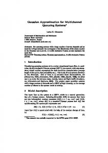
CHAPTER 1. INTRODUCTION
• Arrivals at the SAM are allowed to occur only during arrival sessions. • Arrival sessions have a unique characterization. More specifically, their length as well as the arrival process taking place during the arrival session are uniquely defined (e.g. compared to an arrival session on Friday, an arrival session on Thursday may have a different length and a different arrival process). As such, we allow for a time-dependent arrival process. • Service times have fixed starting times whereas arrival sessions have fixed starting and fixed ending times. Therefore, the time intervals in between these time instances are fixed (i.e. deterministic) as well. Remark that the maximum number of customers allowed to receive service is usually a function of the available capacity during a service session. Often, the number of customers allowed to receive service exceeds the available capacity during a service session (e.g. overbooking practices in health care, transportation, telecommunication . . . ). Conversely, if the number of customers allowed to receive service is less than the available capacity, a safety buffer is installed. In this dissertation we assume the number of customers allowed to receive service to match with the available capacity during a service session. We use an example to illustrate the dynamics of the SAM; refer to Figure 1.2 for a visual representation of the example. Suppose we have an appointment-driven system with service sessions on Thursday (at 12 AM) and on Friday (at 7 AM and at 12 AM). Arrivals are allowed to take place during arrival sessions on Thursday (from 6 AM until 6 PM) and on Friday (from 7 AM until 12 AM). In the example, five customers arrive and are scheduled for service during the first available service session. Remark that the capacity of the first service session has already been depleted (i.e. the number of customers in the waiting list at the start of the first service session is at least equal to the number of customers that is allowed to receive service during that service session). Therefore, the first arriving customer is scheduled for service at the second service session (in which capacity is still available). At the start of a service session, either all customers are removed from the queue or the maximum number of customers allowed to 7
1.2. Modeling approach
Figure 1.2: Dynamics of the SAM
8
CHAPTER 1. INTRODUCTION
receive service during the upcoming service session is removed. The SAM may be considered as a vacation model. Vacation models observe the queueing behavior of systems in which the server takes a vacation (i.e. becomes unavailable) when certain conditions are met. During server vacations, arriving customers are stored in the queue. Once the server returns, service begins once more. A wide variety of vacation models exists. For a general overview we refer to [21, 97, 100]. The SAM has some unique features rendering the modeling exercise rather complex: • Arrival sessions have a unique characterization. • The interarrival times (i.e. the time intervals in between two successive appointments) of customers during a given arrival session follow an i.i.d. phase-type (P H) distribution. • Because customers are served in batches, we have a batch service vacation model. • At the start of each service session, there is a maximum number of customers that is removed from the waiting list. As such, the vacation model has a k-limited service discipline. Remark that service itself (i.e. the removal of up to k customers from the waiting list) occurs instantaneously. • The maximum number of customers removed from the waiting list, depends on the service session that is about to start (e.g. the maximum number of patients served during a service session on Thursday is allowed to differ from the maximum number of patients served during a service session on Friday). As such, the vacation model features time-dependent values of k. • A vacation is initiated at the following time instances: (1) the start of a service session (after the removal of up to k customers); (2) the start of an arrival session; (3) the end of an arrival session. Since these time instances are fixed moments in time, the intervals in between (i.e. the vacation durations) are of fixed (i.e. deterministic) length as well. 9
1.2. Modeling approach
• The deterministic length of a vacation depends on the moment at which the vacation is initiated (e.g. a vacation initiated after a service session on Thursday is allowed to have a different length compared to a vacation that is initiated after a service session on Friday). To summarize, the SAM may be modeled as a batch service vacation model featuring: (1) arrival sessions that have a unique characterization; (2) a k-limited service discipline; (3) vacations of deterministic length; (4) timedependent values of k as well as time-dependent vacation lengths. To the best of our knowledge, no such model exists in the literature on vacation models. The performance measures of interest are: (1) the expected waiting time of a customer at the SAM; (2) the distribution of the number of customers in the waiting list at the start of a service session. Of particular interest is the latter performance measure because it indicates the probability of having to serve a certain number of customers during a given service session. In an upcoming section, we will demonstrate that this performance measure serves as the link between the SAM and the CAS. As such, its accurate assessment is of key importance. Building on Markov chain theory and through the use of P H distributions, matrix analytical methods and efficient algorithms, we obtain numerically exact results for both performance measures. The validity and accuracy of these results are supported by simulation studies. Computational experiments show that real-life systems may be assessed.
1.2.2
CAS
The CAS may be considered as a an appointment system (AS). In short, AS deal with the operational issue of scheduling a number of customers during a service session as to optimize some set of performance measures. In the AS literature, customers are either scheduled using some appointment scheduling rule or a procedure is developed to determine the (optimal) arrival times of customers at the service facility. With respect to appointment scheduling rules, comprehensive comparisons of various rules are available with [41, 42]. In this dissertation, we will focus only on static (i.e. decisions 10
CHAPTER 1. INTRODUCTION
are made prior to the start of the service session) appointment scheduling rules. In the most simple case, all customers arrive punctually at their appointment dates and receive service at a single server workstation. Complexity is introduced in the form of so-called “environmental variables”. An extensive overview of such environmental variables is provided in [17]. The CAS takes into account the following environmental variables: • Customers are allowed to arrive early, late or may even fail to show up. • Customers have a unique arrival process characterization. As such, each customer has its own: (1) probability to show up; (2) probabilities to arrive early or late; (3) distributions to model the amount of time a customer arrives early or late. In addition, these parameters may depend on the scheduled arrival time of the customer at the service facility (e.g. if a customer is scheduled to arrive at the end of a service session, a different arrival process characterization may be adopted compared to the situation in which the customer would have been scheduled to arrive at the start of the service session). • The start of a service session may be delayed due to a “service setup” (e.g. absence or lateness of staff, setup of equipment, . . . ). • The service process of a customer may be interrupted (e.g. a doctor who is called away for an emergency). We allow for both preemptive interrupts (i.e. interrupts that occur during the service process of a customer) and non-preemptive interrupts (i.e. interrupts that occur in between the service process of two successive customers). Despite the availability of models that incorporate customer unpunctuality and customer no-show, no models exist that allow for an individual characterization of the arrival process. In addition, computational performance and model accuracy (and hence practical applicability) of the CAS significantly exceed the capabilities of comparable models in the literature on AS. The CAS has the following properties: 11
1.2. Modeling approach
Figure 1.3: Dynamics of the CAS
• Customers are served by a single server. • Customers have i.i.d. P H service time distributions. • All customers that arrive during the service session are served. • Service is provided even if only a single customer is to be served. • Customers that arrive early (i.e. prior to their scheduled arrival time) receive service if the server is idle. Remark that this implies the possibility of overtaking other customers. • Optimization occurs over a limited set of appointment scheduling rules. We use an example to illustrate the dynamics of the CAS (refer to Figure 1.3 for a visual representation of the example). Suppose we have a service session in which 3 customers need to be scheduled. The mean service time requirement of a customer amounts to exactly 2 hours whereas the service 12
CHAPTER 1. INTRODUCTION
session itself has a total duration of 6 hours. The service session takes place on Thursday and starts at 12AM. Assume we schedule customers using a common variation of the well-known Bailey-Welch appointment scheduling rule. More specifically, we schedule a first customer to arrive at the start of the service session. The other customers are scheduled to arrive at 2 PM and at 4 PM respectively (i.e. the time in between two successive scheduled arrival times equals the mean service time requirement of a customer). In the example, the first customer arrives 15 minutes late resulting in 15 minutes of server idle time (normal operating costs such as staff wages, equipment costs, . . . are still incurred). While service starts immediately upon entry of the first customer, no customer waiting takes place. The second customer on the other hand arrives 15 minutes early and has to wait for 30 minutes prior to receiving service. The third customer arrives on time and is served after a waiting time of 15 minutes. As such, the average waiting time of a customer at the service facility amounts to 15 minutes. The average waiting time of a customer from the start of a service session until the arrival at the service facility amounts to 120 minutes (i.e. on average the customers have waited 120 minutes from the start of the service session until their arrival at the service facility; remark that this waiting time is part of the time spent at the waiting list). The service session itself finishes 15 minutes late, resulting in 15 minutes of server overtime (additional costs such as penalties, staff compensation, . . . might be incurred). The performance measures of interest are: (1) the expected waiting time of a customer at the service facility; (2) the expected waiting time from the start of a service session until the arrival at the service facility; (3) the expected amount of overtime a server performs; (4) the expected amount of time a server resides in an idle state. For any given schedule of customers (i.e. the outcome of any given appointment scheduling rule or scheduling procedure), the CAS may be used to obtain these performance measures. In this dissertation, we limit ourselves to the optimization over a limited set of appointment scheduling rules. The CAS constrains scheduled arrivals to occur only at discrete moments in time. The length of the time interval in between two such observation moments determines the accuracy of the model. The CAS allows for 13
1.2. Modeling approach
Figure 1.4: Dynamics of the SAM
an arbitrary choice of the interval length. Experiments show that time intervals of mere seconds yield computationally feasible results, even if a large number of customers needs to be scheduled (i.e. more than 50 customers). The CAS builds on Markov chain theory and adopts efficient algorithms to obtain the performance measures required. The validity and accuracy of the CAS are supported by a simulation study.
1.2.3
The link between the SAM and the CAS
From the SAM we obtain the probability of having to serve a certain number of customers during a service session. These probabilities are used as a weighting factor for the performance measures of the corresponding CAS in order to assess the performance of an appointment-driven system as a whole (remark that the CAS observes the queueing behavior of a certain number of customers during a given service session). Figure 1.4 builds on the example setting introduced in the previous section and illustrates the logic adhered. In the example, three service sessions take place each week. 14
CHAPTER 1. INTRODUCTION
Figure 1.5: Determining customer waiting at the waiting list
Respectively 3, 1 and 2 customers are allowed to receive service during each service session. The probability of the number of customers to be served during a service session is obtained from the SAM. For each possible outcome (i.e. each possible number of customers to be served) a CAS is analyzed. The previously mentioned probabilities serve as proper weights for the performance measures resulting from the analysis of the different CAS. With respect to the customer waiting time at the waiting list, part is obtained from the SAM (i.e. the customer waiting time at the SAM) and part is obtained from the CAS (i.e. the customer waiting tim from the start of a service session until the arrival at the service facility). Figure 1.5 provides further insight. Notwithstanding the usefulness of observing both systems in their own right, it is clear that the study of the SAM or the CAS separately offers only a myopic view of the performance of an appointment-driven system as a whole. The CAS (or any AS for that matter) optimizes the scheduling 15
1.2. Modeling approach
of a fixed number of customers during a service session without taking into account: (1) the time spent at the waiting list; (2) the probability of having a certain number of customers present during a service session. The SAM on the other hand observes only part of the waiting time of a customer at the waiting list. As such, the SAM ignores: (1) customer waiting at the service facility itself; (2) customer waiting time from the start of the service session until the arrival at the service facility; (3) server overtime; (4) server idle time. Together however, an accurate assessment of an appointment-driven system as a whole may be obtained.
1.2.4
Optimization of an appointment-driven system
Optimizing the performance of an appointment-driven system is equivalent to minimizing: (1) customer waiting time at the waiting list; (2) customer waiting time at the service facility; (3) server idle time; (4) server overtime. At the waiting list, customers wait for an upcoming service session in order to receive service. The more service sessions installed, the less waiting occurs (where the limiting case is a continuous-time queueing model in which service sessions are initiated at every instance in time). Due to the limited availability of service capacity over a unit time interval, the number of service sessions is maximized if the number of customers served during each of these service sessions is minimized. In general, customer waiting time at the waiting list is minimized if the number of customers allowed to receive service during a service session is minimized as well. Customer waiting time at the service facility, server idle time and server overtime result from: (1) the stochastic nature of the service and arrival processes; (2) the scheduling of arrival times of customers. In order to schedule the arrival of customers at the service facility we adopt an AS. In general three settings emerge (refer to Figure 1.6 for a visual illustration of each of these settings): • The scheduled interarrival times of customers are smaller than the mean service time. Each additional customer that is allowed to receive service during a service session: – Increases the expected customer waiting time (due to the buildup 16
CHAPTER 1. INTRODUCTION
Figure 1.6: Different AS settings
17
1.2. Modeling approach
of the queue; as more customers arrive, the probability of having a larger queue size increases). – Decreases the expected server idle time (due to the the buildup of a workload buffer). – Decreases the expected server overtime (due to the effect of the law of large numbers; resulting in pooling benefits). • The scheduled interarrival times of customers are larger than the mean service time. Each additional customer that is allowed to receive service during a service session: – Increases the expected customer waiting time (due to the buildup of the queue; the probability of finding an idle server upon arrival decreases as the number of customers allowed to receive service during a service session increases; this effect is less outspoken when compared to the previous setting). – Increases expected server idle time (due to the safety buffer that is installed in between the service of two consecutive customers). – Increases the expected server overtime (assuming server overtime is incurred after a time capacity equalling the sum of the service times of all customers allowed to receive service during the service session). • The scheduled interarrival times of customers equal the mean service time of a customer. The number of customers allowed to receive service during a service session does not impact system performance if service and arrival processes are devoid of stochasticity (i.e. each customer arrives on time, completes service after a deterministic amount of time and leaves the facility upon arrival of the next customer). System performance deteriorates with increased variability. One may conclude: • it is optimal to minimize the number of customers served during a service session if one wants to minimize customer waiting time. 18
CHAPTER 1. INTRODUCTION
Figure 1.7: Different effects characterizing the optimization problem at an appointment-driven system
• it is optimal to maximize the number of customers served during a service session if one wants to minimize server idle time and server overtime. A graph of the different effects that characterize the optimization problem at an appointment-driven system is presented in Figure 1.7.
1.3
Literature review
In this section we discuss the literature on vacation models and AS and situate our work therein.
1.3.1
Vacation models
Over the past decades, queueing systems with server vacations have received a lot of attention in the queueing literature. Vacation models are queueing systems in which the server is allowed to take a vacation (i.e. to become 19
1.3. Literature review
unavailable) when certain conditions are met. During a vacation, arriving customers are stored in a queue. Upon server return, service begins once more. Excellent overviews of the literature on vacation models may be found with [21, 97, 100]. Considering the vast amount of literature available, we focus only on those topics relevant to our discourse. Vacation models with limited service discipline serve customers either until a predefined timer expires or until a certain number of customers is served. In the latter case, the service discipline is referred to as a k-limited service discipline. The analysis of such systems is reported to be notoriously hard [12, 91]. Most vacation models with limited service disciplines yield only approximative results or impose restrictive assumptions on either the maximum value of k or the distribution of arrivals, services and/or vacation lengths. In pure limited (P-limited) service systems, k is assumed to equal unity. Examples of such systems may be found with [29, 54, 93]. General limited (G-limited) service systems allow for larger values of k. G-limited systems have been observed in [30, 40]. The P-limited and G-limited models discussed here assume: (1) exponential interarrival times of customers; (2) a single value of k that is valid for all service sessions (i.e. k is assumed to be time-independent). No research exists in which the value of k depends on the time in the system. A wide variety of possible combinations of service and arrival distributions have been presented in literature. Most vacation models assume a Poisson arrival process and general service times [95]. However, some research has also been performed on Markovian arrival processes (MAP) [62] and batch Markovian arrival processes (BMAP) [3, 74, 89]. Batch services have been considered in [50, 92]. With respect to the vacation itself, most models assume its length to be exponentially distributed [36]. P Hdistributed vacation lengths are assumed in [98]. Vacation models in which the length of a vacation depends on the state of the system are presented in [89, 114]. These models however, assume vacation lengths to depend on the number of customers in the system present at the beginning of a vacation. No research exists in which the length of a vacation depends on the time in the system (i.e. the moment at which a vacation is initiated). Arrival sessions seem to be a new feature of vacation queueing models. 20
CHAPTER 1. INTRODUCTION
We found no related literature. One may conclude that only few features of the SAM are modeled in the available literature on vacation models.
1.3.2
Appointment systems
AS are scheduling systems that have the goal of matching capacity and demand as to optimize some set of performance measures. They have been studied extensively over the past 50 years. AS arise in many constexts in which appointment decisions are economically significant. In transportation, AS have been used to schedule the arrival of cargo ships and trucks at ports [31, 70, 88], to schedule railway operations [55, 109] and to allocate airport slots [63, 64]. AS have also been adopted in telecomunication networks to schedule data transmissions [56, 86]. In manufacturing settings, AS have been used to schedule deliveries in just-in-time inventory systems [58, 104], to support lot-sizing decisions [19] and to schedule job release times [9, 99, 113]. The bulk of the AS literature however, deals with the scheduling of patients in a health care context. Excellent overviews of the relevant literature may be found with [17, 68]. Optimization of customer appointment times usually occurs over some subset of: (1) server idle time; (2) server overtime; (3) customer waiting time at the service facility. Most of the research observes either server idle time or server overtime. Few studies assess the trade-off between all three performance measures. Examples of these latter studies may be found with [20, 25, 49]. Nearly all of the literature on AS deals with the scheduling of customers during a single service session. Studies observing AS ranging over multiple service session are scarce. In [85] a “rolling horizon” concept is used to schedule customers over two service sessions (before lunch and after lunch). In [14] customers are scheduled over several days using a heuristic approach. The computational complexity involved, limits applicability of their model to settings in which only a small number of customers can be scheduled. With respect to environmental variables, it has long been known that no-shows have a dire impact on the performance of an AS [37, 41]. As such, all but a few studies allow the not showing up of customers. Some of the research encountered also considers the occurrence of walk-ins (i.e. 21
1.3. Literature review
unscheduled customers). Examples of such studies may be found with [24, 52, 84, 85, 96, 102]. The modeling of customer unpunctuality is less prevalent. Relevant literature includes [24, 66, 67, 88, 102, 104, 110]. Most of these models only allow for the late arrival of customers. In addition, all studies assume customer unpunctuality to be independent from the scheduled arrival times. Staff lateness (such that service cannot commence at the start of a service session) is considered in [1, 24, 60, 61, 102, 110]. Server interruptions are modeled in [57, 82]. Both simulation models however, assume interrupts only to occur in between the service process of two subsequent customers (i.e. they assume non-preemtive interrupts). The bulk of the AS literature assumes that customers are scheduled for arrival at discrete moments in time only. Individual appointment scheduling rules assume a single customer to be scheduled at each of the discrete appointment times. Often the time intervals between two such discrete appointment times are assumed to be fixed. Such studies may be found with [2, 24, 52, 84, 108]. When allowing for multiple initial appointments (i.e. as to minimize the server idle time at the beginning of a service session) individual appointment rules with fixed intervals are observed in [2, 41, 42, 47, 52, 110]. Block appointment rules allow the scheduling of multiple customers at each of the discrete appointment times (i.e. during each of the “blocks”). In [94, 110] fixed block sizes (i.e. the number of appointments made at each of the discrete appointment times) as well as fixed block lenghts (i.e. the time interval in between two successive discrete appointment times) are assumed. Variable block sizes and fixed intervals have been studied in [25, 58, 60, 61, 82]. Fixed block sizes and variable intervals are analyzed in [14, 78, 105]. Variable block sizes and variable intervals have not yet been studied. The literature on AS often assumes a homogenous customer population. Some studies however allow customers to have distinct service requirements. Most of these studies do not only optimize the scheduling of customers, but do also optimize the sequence of customers to be served [14, 15, 52, 84, 106]. With respect to distinct arrival characterization of customers, no relevant literature was found. 22
CHAPTER 1. INTRODUCTION
1.4
Thesis outline
In this first chapter we define the research objective and motivate its practical relevance. We show that appointment-driven systems are linked to a number of key strategic issues that affect various large industries. We describe the dynamics of an appointment-driven system and demonstrate that it is in fact a combination of two queueing systems. We refer to these queueing systems as the SAM and the CAS respectively. We provide an intuitive modeling approach and illustrate the link between both queueing models. In addition, we discuss the optimization of an appointment-driven system. A review of the literature situates our work in the domain of AS and vacation models. In this section, we further describe the contents of the dissertation and its organization in terms of chapters. Chapter 2 is committed to the SAM. The SAM observes the arrival process of customers at the waiting list and assigns them to receive service at some future service session. We describe its basic processes and develop a two-moment matching procedure to obtain the P H distributions that approximate the input processes. In addition, we establish a counting process that allows the numerically exact assessment of various performance measures at the SAM. The SAM itself is a complex vacation model. We develop a number of efficient, numerically exact algorithms and adopt matrix analytical methods in order to obtain the required performance measures (customer waiting time at the SAM and the distribution of the number of customers to be served during a service session). The validity, accuracy and computational performance of the SAM are verified using a simulation study. A numerical example provides further insight in the dynamics of the SAM. Chapter 3 is committed to the CAS. The CAS observes the queueing behavior of a customer during a service session itself. We describe its basic processes and establish a discretization procedure that is used to adapt the input distributions. The dynamics of the AS are captured using a multidimensional DTMC. Efficient algorithms are used to assess the performance measure outcomes of an appointment scheduling rule (or procedure). We present a number of extensions that allow the late start of a service session and the interruption of the service process of a customer. We adopt the CAS 23
1.4. Thesis outline
to obtain the performance measure outcomes (customer waiting time at the service facility, server idle time and server overtime) of a set of 314 appointment scheduling rules in a wide variety of operating environments. These performance measure outcomes are used to establish a number of so-called “efficient frontiers”. Using the efficient frontiers, the performance of the appointment scheduling rules (in terms of rule dominance, distance towards the efficient frontier and relative location compared to the efficient frontier) is assessed; allowing us to identify a set of “good” appointment scheduling rules. This set of robust, well-performing scheduling rules is used to assess the impact of various environmental variables. We conclude Chapter 3 by means of a numerical example. Chapter 4 links both the SAM and the CAS in order to obtain the performance measures of an appointment-driven system. We aggregate the results of both queueing models and perform an extensive experiment to: (1) illustrate the dynamics of the waiting list; (2) generate some general insights; (3) assess the performance of the set of “good” appointment scheduling rules in a wide variety of operating environments. A numerical example provides further insight in the optimization of an appointment-driven system. Chapter 5 concludes this dissertation. We summarize the main results of each chapter and provide directions for future research.
24
Chapter 2
Service Allocation Model In this chapter we discuss the service allocation model (SAM). In Section 2.1, we define the problem setting and establish all basic processes governing the SAM. The model itself is presented in Section 2.2. The validity, the accuracy and the computational performance of the SAM is verified in Section 2.3. This final section also provides a numerical example.
2.1
Definitions
In what follows we define the basic processes that govern the SAM, characterize the P H distributions used to model system processes and establish a counting process to determine the distribution of the number of arriving customers during a vacation.
2.1.1
Basic Processes
The service process of an appointment-driven system is a succession of service sessions during which customers are served. Each service session is is characterized by the maximum number of customers kis allowed to receive service. We assume recurring cycles to be present in the succession of service sessions (e.g. a doctor receiving patients every Thursday and Friday). A cycle of service sessions has length Tcs . Similarly to the service process, the arrival process is a succession of arrival sessions ia during which customers are allowed to make appointments. 25
2.1. Definitions
Figure 2.1: Cyclic nature of the service and arrival process
An arrival session ia is fully characterized by: (1) the length Tia ; (2) the 2 mean interarrival time λ−1 ia ; (3) the variance of interarrival times σia . We assume recurring cycles to be present in the succession of arrival sessions. A cycle of arrival sessions has length Tca . An illustration of the cyclic nature of service and arrival processes is provided in Figure 2.1. In building the SAM, we will fully exploit the repetitive structure of the service and arrival processes. The vacation process is obtained when superimposing both the service and the arrival process. The vacation process is the continuous (i.e. uninterrupted) succession of vacations iv , of deterministic length Tiv . A new vacation iv is initiated at each instance in time at which (1) a service session starts; (2) an arrival session starts; (3) an arrival session ends. This observation is used to determine Tiv . We illustrate this procedure in Figure 2.2. Because service and arrival processes are assumed to be cyclic, the vacation process is cyclic as well. The cycle length of the vacation process Tcv equals the least common multiple of Tcs and Tca (assuming the ratio of Tcs and Tca is a rational number). A cycle of vacations contains J vacations (for the remainder of the text, index j is defined as j ∈ {1, 2, . . . , J}). We illustrate these principles in Figure 2.3. Remark that, due to the cyclic nature of the vacation process, a vacation of type (j +(iJ)) is also a vacation of type j (for 26
CHAPTER 2. SERVICE ALLOCATION MODEL
Figure 2.2: The vacation process at the SAM
Figure 2.3: Cyclic nature of the vacation process
27
2.1. Definitions
the remainder of the text, index i is defined as i ∈ {0, 1, . . .}). In addition, vacations may be divided into different classes (e.g. arrivals are allowed to take place only during vacations of a particular class). A definition of the different vacation classes is presented in section 2.2.1.1.
2.1.2
Phase-Type Distributions
In order to model a general i.i.d. arrival process, we adopt continuoustime P H distributions. Continuous time P H distributions use exponentially distributed building blocks to approximate (with arbitrary precision) any positive-valued continuous distribution. P H distributions are widely implemented in the queueing literature. For a review on the literature and an introduction on P H distributions we refer to [53, 73, 77] among others. A P H distribution is the distribution of time until absorption in a Markov chain with absorbing state 0 and state space {0, 1, . . . , ζ, ζ + 1}. It is fully characterized by parameters τ and Z. τ is the vector of initial probabilities to start the process in any of the (ζ + 1) transient states and Z is the matrix containing the transition rates between transient states. The infinitesimal generator of the Markov chain representing the P H distribution is presented below: 0 0 Q= , t Z where 0 is a matrix of appropriate dimension containing only zeros and (t = −Ze) (with e a vector of ones of appropriate size). In this dissertation we adopt simple P H approximations of the arrival process. Whereas a multitude of approximations are available (ranging from very simple procedures to complex algorithms), we limit ourselves to the matching of the first two moments of the interarrival time distribution 2 (i.e. λ−1 ia and σia ; the respective mean and variance of the interarrival time distribution are matched by the P H distribution). For notational conve2 nience, let λ−1 j and σj denote the mean and variance of the interarrival time distribution of arrivals during a vacation of type j. The two-moment matching procedure developed in this section minimizes Mj , the number of phases required to approximate the arrival process at a vacation of type j. Define Mj ; the set containing the different arrival phases of the arrival process at 28
CHAPTER 2. SERVICE ALLOCATION MODEL
a vacation of type j (as such, (|Mj | = Mj )). Of course, if no arrivals are allowed to occur during a vacation of type j, (Mj = 0) and (Mj = ∅). If arrivals are allowed to occur, we make a distinction between three cases: (1) (Cj2 = 1); (2) (Cj2 > 1); (3) (Cj2 < 1) (where (Cj2 = σj2 λ2j ) denotes the squared coefficient of variation of interarrival times at a vacation j). This distinction allows us to minimize the number of phases required to match the first two moments of any positive-valued continuous distribution. In the first case, a simple exponential distribution of parameter λj suffices to approximate the arrival process. τ j and Zj are given by: τj = 1 ,
Zj = −λj .
In the second case, we model the arrival process using a convex mixture of 2 exponential distributions (i.e. using a hyper-exponential distribution). The parameters of the hyper-exponential distribution matching the interarrival time distribution with rate λj and variance σj2 are given by: 2 , 2 − Cj4 + Cj6
υj1
=
υj2
= 1 − υj1 , � 1 2 − Cj2 + Cj4 , = 2λj 1 1 , − = λj λj Cj2
λ−1 j1 λ−1 j2
(2.1) (2.2) (2.3) (2.4)
where υj1 , υj2 , λj1 and λj2 denote the probability of having an interarrival time that is exponentially distributed with parameter λj1 , the probability of having an interarrival time that is exponentially distributed with parameter λj2 , the parameter of the first exponential distribution and the parameter of the second exponential distribution respectively. τ j and Zj are defined as: 1 2 τj = 1 . υj1 , Zj = 1 −λj1 0 2 υj2 2 0 −λj2 With respect to the third case, we model the arrival process using a hypoexponential distribution (a series of exponential distributions whose parameters are allowed to differ; a generalization of the Erlang distribution). 29
2.1. Definitions
The parameters of the hypoexponential distribution matching the interarrival time distribution with rate λj and variance σj2 are given by: ζj λ−1 j1
= bCj−2 c − bCj2 bCj−2 cc, r Cj2 ζj ζj ζj + − + + 2 λj λj λ2j = ζj + ζj2
λ−1 = j2
zj2
1 �− − � λj λj ζj + ζj2
(2.5) Cj2 ζj2 λ2j
ζj
,
(2.6)
r ζ − λj2 + j
Cj2 ζj λ2j
+
Cj2 ζj2 λ2j
ζj + ζj2
,
(2.7)
where ζj , λj1 and λj2 denote the number of phases of exponential duration of parameter λj1 that occur prior to the last phase, the parameter of the exponentially distributed interarrival times at the first ζj phases, the parameter of the exponentially distributed interarrival time at the last phase. τ j and Zj are presented below:
τj =
1 2 .. .
1 0 .. .
ζj ζj + 1
0 0
,
Zj =
1 2 .. .
1 −λj1 0 .. .
2 λj1 −λj1 .. .
··· ··· ··· .. .
ζj 0 0 .. .
ζj + 1 0 0 .. .
ζj ζj + 1
0 0
0 0
··· ···
−λj1 0
λj1 −λj2
For the three cases, Mj equals 1,2 and ζj + 1 respectively. A summary of the P H distributions, used to model the SAM, is provided in Figure 2.4.
2.1.3
Counting process
A counting process is established in order to obtain the distribution of the number of customers arrived during a vacation of type j. The counting process developed here builds on the insights presented in [81]. Define Pj [i, d|0, c] as the probability of having i arrivals during a vacation of type j and an arrival process at final phase d (d ∈ Mj ) given: (1) a P H distribution of parameters Zj and τ j ; (2) an arrival process at initial phase 30
.
CHAPTER 2. SERVICE ALLOCATION MODEL
Figure 2.4: Overview of P H distributions used at the SAM
c (c ∈ Mj ). The distribution of the number of arrivals may be obtained through a counting process of the MAP (Markovian Arrival Process) characterized by Cj0 and Cj1 . The counting process has a continuous-time rate matrix: Cj0 Cj1 0 0 · · · 0 C 0 · · · j0 Cj1 0 Cj0 Cj1 · · · , Qj = 0 0 0 0 Cj0 · · · · · · · · · · · · · · · ... � � where (Cj0 = Zj ) and Cj1 = tj τ > j . The transition probabilities of the counting process during a vacation of deterministic length Tj are given by: Cj (Tj ) = e
Tj Qj
=
∞ X Tji i=0
i!
Qij .
(2.8)
In order to avoid numerical problems and to enhance computational performance, we apply a uniformization argument to the counting process. More specifically, define: Qj Pj = max + I, (2.9) λj 31
2.2. Model
where I is an identity matrix of appropriate dimension and λmax is the j largest rate of the P H distribution of parameters Zj and τ j . We have [101]: Cj (Tj ) = e
−Tj λmax j
∞ X (Tj λmax )i j i=0
i!
Pij .
(2.10)
Since we are only interested in transitions moving from states with queue size zero, we only need to observe the first block row of Cj (Tj ). More specifically, the first block row of Cj (Tj ) holds the distribution of the number of arrivals during a vacation of type j (i.e. probabilities Pj [i, d|0, c]). In order to obtain (i) the first block row of Cj (Tj ), it suffices to compute Pj1 ; the first block row of (i)
Pij (∀i ≥ 0). Pj1 may be obtained through the simple recursive relationship: ! " # Cj1 (i−1) Cj0 (i−1) (i) + I P j1 + 0 P j1 . (2.11) P j1 = λmax λmax j j
2.2
Model
The SAM is not a straightforward queueing model. One possible approach to model the SAM is to construct a Markov chain of four dimensions: (1) the queue size Q : Q ∈ {0, 1, 2, . . .}; (2) the vacation type j; (3) the phase of the arrival process m : m ∈ {1, . . . , Mj }; (4) the phase of the vacation process v : v ∈ {1, . . . , V }. Unfortunately, the use of multidimensional Markov chains is in general not advisable since it is clear that, as J, Mj or V increase, the resulting statespace grows rapidly. When modeling real life problems, memory and computational constraints are quickly met. In order to efficiently assess performance measures, we decompose the systems into two subsystems: • A first subsystem observes the queueing process of customers only at the start of a vacation of type j, prior to the removal of up to kj customers. We use a set of DTMC X (X = {X1 , . . . , XJ } and Xj = {Xj (t) : t ≥ 0}) to analyze this first subsystem. From the analysis of the DTMC Xj , we obtain: – The distribution of the number of customers in queue at the start of a vacation of type j, prior to the removal of up to kj customers. 32
CHAPTER 2. SERVICE ALLOCATION MODEL
Figure 2.5: System decomposition at the SAM
– Qj ; the expected number of customers in queue during a vacation of type j, given that these customers did already arrive prior to the start of vacation j. • A second subsystem observes the queueing process of those customers who arrive during a vacation of type j. Using simple arithmetics, we obtain Q∗j ; the expected number of customers in queue during a vacation of type j, given that these customers did arrive during vacation j. We illustrate the decomposition in Figure 2.5. Decomposing the system significantly improves computational efficiency due to: (1) dimensional reduction (Xj is a two-dimensional DTMC); (2) avoiding unnecessary computations. In what follows we describe the DTMC Xj and develop the arithmetics required to obtain the relevant performance measures. In a final section we combine these performance measures to obtain general results at the SAM. 33
2.2. Model
Figure 2.6: The set of DTMC X
2.2.1
The DTMC Xj
The DTMC Xj observes the queueing behavior of customers at the start of a vacation of type j prior to the removal of up to kj customers from the queue. Therefore, observation moments coincide with the start of a vacation. The actions taking place in between two successive observation moments (i.e. the start of a vacation of type j and the start of the next vacation of type j) are left unobserved. We refer to Figure 2.6 to illustrate this principle. In order to take the unobserved alterations of the queueing process into account, one needs to compute all possible outcomes (i.e. resulting queue sizes) and their corresponding probabilities. More specifically, one wants to know the probability of having t customers in the queue at the beginning of a vacation of type j, given that at the beginning of the previous vacation of 34
CHAPTER 2. SERVICE ALLOCATION MODEL
type j s customers were present in the queue. The DTMC Xj may be defined as a two dimensional stochastic process whose statespace can be represented by pairs (Q, m)j . Define Pj,n [t, d|s, c] as the probability of moving from a state with queue size s and arrival phase c at the start of a vacation j towards a state with queue size t and arrival phase d at the start of vacation (j + n) (c ∈ Mj ∧ d ∈ Mj+n ). In order to obtain Pj,J [t, d|s, c] (i.e. the transition probabilities of the DTMC Xj ), we first determine Pj,1 [t, d|s, c] by means of the counting process that was outlined in section 2.1.3. These latter probabilities serve as the input of an iterative algorithm that yields the required transition probabilities Pj,J [t, d|s, c]. In what follows we first provide a classification of the different vacation classes and show how to obtain Pj,1 [t, d|s, c] for each vacation class. Next we propose an algorithm to compute probabilities Pj,J [t, d|s, c] and use these probabilities to construct the DTMC Xj . We use matrix analytical methods to obtain the stationary distribution of the number of customers in the queue at the start of a vacation of type j, prior to the removal of up to kj customers from the queue. In addition, we develop the arithmetics required to compute the expected number of customers in queue during a vacation of type j. Finally, we present an alternative algorithm that further improves computational performance. 2.2.1.1
A Classification of Vacations
A distinction between five classes of vacations may be made: • Class 1 vacations coincide with the end of an arrival session but do not coincide with the start of a service session. • Class 2 vacations coincide with the start of a service session, do not coincide with the start of an arrival session and no arrival session is still in progress. • Class 3 vacations coincide with the start of an arrival session but do not coincide with the start of a service session. • Class 4 vacations coincide with both the start of an arrival session and the start of a service session. 35
2.2. Model
Figure 2.7: Overview of different vacation classes
• Class 5 vacations coincide with the start of a service session, do not coincide with the start of an arrival session and an arrival session is still in progress. We do not allow for (multiple) adjacent arrival sessions because of the limitations involved with the P H distributions adopted in this dissertation. Multiple adjacent arrival sessions however, might be used to take into account time-dependencies in the arrival process. The different classes of vacations are illustrated in Figure 2.7. Let cj : cj ∈ {1, 2, 3, 4, 5} denote the class of a vacation j. Depending on the class, a vacation j is characterized by: • a deterministic length Tj (∀j : cj ∈ {1, 2, 3, 4, 5}), • a maximum number of customers kj that is served instantaneously at the start of a vacation j (∀j : cj ∈ {2, 4, 5} and (kj = 0) for all j : cj ∈ {1, 3}), • a mean interarrival time λ−1 and variance σj2 (∀j : cj ∈ {3, 4, 5}). j Remark that (Mj = 0) and (Mj = ∅) for all vacations j : cj ∈ {1, 2}. 36
CHAPTER 2. SERVICE ALLOCATION MODEL
Each of the vacation classes requires a distinct modeling approach. Class 1 Vacation Since no arrivals nor service takes place, the queueing process remains unaltered during class 1 vacations. If vacation (j + 1) is of class 2, we have (remark that a vacation j of class cj ∈ {1, 2} can never be succeeded by a vacation (j + 1) of class cj+1 ∈ {1, 5}): ( Pj,1 [t, ∅|s, ∅] =
1 ∀s, t : s = t, 0 otherwise.
(2.12)
τ j+1 (d) ∀s, t : s = t, 0 otherwise,
(2.13)
For cj+1 ∈ {3, 4}, we have: ( Pj,1 [t, d|s, ∅] =
where τ j+1 (d) indicates the probability of starting the arrival process of a vacation (j + 1) at an arrival phase d (refer to section 2.1.2 for a definition of τ j ). Class 2 Vacation Since no arrivals are allowed to take place, the queueing process remains unaltered during class 2 vacations. However, at the start of a class 2 vacation j, a maximum of kj customers is removed from the queue. If (cj+1 = 2), we have: 1 ∀s, t : s > kj ∧ t = s − kj , Pj,1 [t, ∅|s, ∅] = (2.14) 1 ∀s, t : s ≤ kj ∧ t = 0, 0 otherwise. For cj+1 ∈ {3, 4}, we have: τ j+1 (d) ∀s, t : s > kj ∧ t = s − kj , Pj,1 [t, d|s, ∅] = τ j+1 (d) ∀s, t : s ≤ kj ∧ t = 0, 0 otherwise.
(2.15)
37
2.2. Model
Class 3 Vacation For a given vacation j we use the counting process developed earlier to obtain the distribution of the number of customers arrived. No services takes place at a class 3 vacation. For cj+1 ∈ {1, 2}, we have:
Pj,1 [t, ∅|s, c] =
P Pj [i, d|0, c] ∀s, t : t − s = i, d∈Mj
0
(2.16)
otherwise.
If (cj+1 = 5), we have (remark that a vacation j of class cj ∈ {3, 4, 5} can never be succeeded by a vacation (j + 1) of class cj+1 ∈ {3, 4}): ( Pj,1 [t, d|s, c] =
Pj [i, d|0, c] ∀s, t : t − s = i, 0 otherwise.
(2.17)
Remark that class 3 vacations are not preceded by a vacation during which arrivals are allowed to take place. As such, the initial arrival phase probabilities are given by τ j . This observation also holds for class 4 vacations. Class 4 Vacation Similar to class 3 vacations, we obtain the distribution of the number of customers arrived by means of the counting process discussed previously. At the start of a class 4 vacation j, a maximum of kj customers is removed from the queue. For cj+1 ∈ {1, 2}, we have: P P [i, d|j, 0, c] ∀s, t : s > kj ∧ t = s + i − kj , j d∈M P Pj,1 [t, ∅|s, c] = Pj [i, d|0, c] ∀s, t : s ≤ kj ∧ t = i, d∈Mj 0 otherwise. (2.18) If (cj+1 = 5), we have: Pj [i, d|0, c] ∀s, t : s > kj ∧ t = s + i − kj , Pj,1 [t, d|s, c] = Pj [i, d|0, c] ∀s, t : s ≤ kj ∧ t = i, 0 otherwise. 38
(2.19)
CHAPTER 2. SERVICE ALLOCATION MODEL
Class 5 Vacation Class 5 vacations are identical to class 4 vacations except for their definition of the initial arrival phase probabilities. Whereas the start of a class 4 vacation coincides with the start of a new arrival session (i.e. initial arrival phase probabilities are given by τ j ), the start of a class 5 vacation occurs while an arrival process is already in progress. As such, the initial arrival probabilities should reflect the phase of the arrival process at the start of the class 5 vacation (i.e. the initial arrival process phase equals the final arrival process phase of the previous vacation). 2.2.1.2
Algorithm
The algorithm developed in this section serves the purpose of computing Pj,J [t, d|s, c]; the probability of moving from a state (s, c)j at the start of a vacation of type j towards a state (t, d)j+J at the start of the next vacation of type j. Define Pj,n [u, e|(s, t), (c, d)] as the probability to depart from a state (s, c)j at the start of a vacation j, to visit state (t, d)j+n−1 at the start of vacation (j + n − 1) and to end up in state (u, e)j+n at the start of vacation (j + n) (c ∈ Mj ∧ d ∈ Mj+n−1 ∧ e ∈ Mj+n ). We assume at least two vacations to be present in a vacation cycle (i.e. (J ≥ 2); if (J = 1) the requested probabilities Pj,J [t, d|s, c] are given by Pj,1 [t, d|s, c]). Before advancing to the algorithm itself, a number of important properties are established: Property 1 When moving from the start of a! vacation j to the start of a J P vacation (j + J), no more than Qc = kj customers can be removed j=1
from the queue. Property 2 Pj,J [t, d|s, c] = Pj,J [(t + i), d|(s + i), c]
∀s : s ≥ Qc .
One of the practical implications of these properties is that only states with queue sizes up to Qc have to be evaluated by the algorithm, resulting in a significant reduction of memory and computational requirements. The algorithm consists of two main steps: (1) iteration; (2) evaluation. In the upcoming sections, we discuss these steps in detail. A final section provides a general outline of the algorithm. 39
2.2. Model
Step 1: Iteration Prior to starting the first iteration step we initialize a counter (n = 2) and compute all probabilities Pj,1 [t, d|s, c] for all vacations j and all possible queue sizes and arrival phases. In a first phase of the iteration step, compute all probabilities Pj,n [u, e|(s, t), (c, d)] as follows: Pj,n [u, e|(s, t), (c, d)] = Pj,(n−1) [t, d|s, c]P(j+n−1),1 [u, ∅|t, ∅] P j,(n−1) [t, d|s, c]P(j+n−1),1 [u, e|t, ∅] Pj,(n−1) [t, d|s, c]P(j+n−1),1 [u, ∅|t, d] Pj,(n−1) [t, d|s, c]P(j+n−1),1 [u, e|t, d]
∀cj+n−1 ∀cj+n−1 ∀cj+n−1 ∀cj+n−1
∈ {1, 2} ∧ ∀cj+n = 2, ∈ {1, 2} ∧ ∀cj+n ∈ {3, 4} , ∈ {3, 4, 5} ∧ ∀cj+n ∈ {1, 2} , ∈ {3, 4, 5} ∧ ∀cj+n = 5,
(2.20)
where Pj,(n−1) [t, d|s, c] is either computed in a previous iteration step or is given by Pj,1 [t, d|s, c]. In the second phase of the iteration step, we aggregate all resulting probabilities over t and d and obtain probabilities Pj,n [u, e|s, c] as follows: Pj,n [u, e|s, c] =
∞ X
X
Pj,n [u, e|(s, t), (c, d)].
(2.21)
t=0 d∈Mj+n−1
After aggregation, we proceed to the evaluation step. Step 2: Evaluation At the evaluation step we evaluate if (n = J). If the condition holds, we have obtained the required probabilities Pj,J [t, d|s, c]. If the condition does not hold, we increment the counter n and proceed to another iteration step. Discussion A general outline of the algorithm is provided in Algorithm 2.1. The computational efficiency of Algorithm 2.1 follows from the aggregation of probabilities Pj,n [u, e|(s, t), (c, d)] and the limitation of initial queue size s : s ≤ Qc . When disregarding the complexity resulting from the computation � of Pj,1 [t, d|s, c], the complexity of � Algorithm 2.1 may be expressed
3 as O (J − 2) (Qc + 1) (Qmax + 1)2 Mmax ; where:
• Mmax = max(Mj ) : j ∈ {1, . . . , J}, 40
CHAPTER 2. SERVICE ALLOCATION MODEL
Algorithm 2.1 Algorithm to obtain Pj,J [t, d|s, c] for all Vacations j do for all s, t, c, d do Compute Pj,1 [t, d|s, c] end for end for for all Vacations j do Set n = 2 while n < J do for all s, t, u, c, d, e do Pj,n [u, e|(s, t), (c, d)] = Pj,(n−1) [t, d|s, c]P(j+n−1),1 [u, e|t, d] end for for all s, u, c, e do ∞ P P Pj,n [u, e|s, c] = Pj,n [u, e|(s, t), (c, d)] t=0 d∈Mj+n−1
end for Increment n end while end for
41
2.2. Model
• Qmax is the maximum number of customers that has a nonzero probability to arrive during any vacation j. Remark that: • ∀s : s ∈ {0, . . . , Qc }, • ∀t, u : t, u ∈ {0, . . . , Qmax }, • ∀c, d, e : c, d, e ∈ {1, . . . , Mmax }. 2.2.1.3
Stationary distribution of the DTMC Xj
To obtain the stationary distribution at a vacation j, we define P j as the transition matrix of the DTMC Xj . Following directly from Property 1 and 2 we have that: Pj,J [t, d|s, c] = 0 ∀s > Qc ∧ t < (s − Qc ) , Pj,J [t, d|s, c] = Pj,J [(t + i), d|(s + i), c] ∀s ≥ Qc . (2.22) In other words, if (s > Qc ), it is impossible to deplete the queue when moving from a state (s, c)j at the start of a vacation of type j towards a state (t, d)j+J at the start of the next vacation of type j. In addition, if (s ≥ Qc ), transition rates moving from states at the start of a vacation of type j towards the start of the next vacation of type j are equal given: (1) equal arrival phases (c, d); (2) equal difference in queue sizes (s, t) and (s + i, t + i). These properties endow the Markov chain P j with a special, repetitive structure. More specifically, P j may be represented as a non-skipfree M/G/1 Markov chain [28]: Bj,0,0 Bj,0,1 Bj,0,2 Bj,0,3 · · · Bj,1,1 Bj,1,2 Bj,1,3 ··· Bj,1,0 .. .. .. .. .. . . . . . Bj,Qc −1,0 Bj,Qc −1,1 Bj,Qc −1,2 Bj,Qc −1,3 · · · , Pj = A A A A · · · j,0 j,1 j,2 j,3 0 Aj,0 Aj,1 Aj,2 ··· 0 0 Aj,0 Aj,1 · · · .. .. .. .. . . . . . . . 42
CHAPTER 2. SERVICE ALLOCATION MODEL
where Aj,i and Bj,s,t are Mj × Mj matrices that depend on the P H distribution used to model the arrival process at a vacation of type j. If no arrivals are allowed to occur during a vacation of type j (i.e. cj ∈ {1, 2}), Aj,i and Bj,s,t are scalars and are given by: Bj,s,t Aj,i
= =
Pj,J [t, ∅|s, ∅], Pj,J [i, ∅|Qc , ∅].
If arrivals are allowed to occur, we once more make a distinction between three cases. In the case of (Cj2 = 1), Aj,i and Bj,s,t are scalars and are given by: Bj,s,t Aj,i
= =
Pj,J [t, 1|s, 1], Pj,J [i, 1|Qc , 1].
In the case of (Cj2 > 1) we have: Bj,s,t =
Aj,i =
1 Mj
1 Mj
1 Mj Pj,J [t, 1|s, 1] Pj,J [t, Mj |s, 1] Pj,J [t, 1|s, Mj ] Pj,J [t, Mj |s, Mj ]
1 Mj Pj,J [i, 1|Qc , 1] Pj,J [i, Mj |Qc , 1] Pj,J [i, 1|Qc , Mj ] Pj,J [i, Mj |Qc , Mj ]
,
.
With respect to the hypoexponential case (i.e. (Cj2 < 1)), Bj,s,t is defined as follows: Bj,s,t = 1 2
1 Pj,J [t, 1|s, 1] Pj,J [t, 1|s, 2]
2 Pj,J [t, 2|s, 1] Pj,J [t, 2|s, 2]
. . . ζj Mj
. . . Pj,J [t, 1|s, ζj ] Pj,J [t, 1|s, Mj ]
. . . Pj,J [t, 2|s, ζj ] Pj,J [t, 2|s, Mj ]
··· ··· ··· .
.
.
··· ···
ζj Pj,J [t, ζj |s, 1] Pj,J [t, ζj |s, 2]
Mj Pj,J [t, Mj |s, 1] Pj,J [t, Mj |s, 2]
. . . Pj,J [t, ζj |s, ζj ] Pj,J [t, ζj |s, Mj ]
. . . Pj,J [t, Mj |s, ζj ] Pj,J [t, Mj |s, Mj ]
.
and Aj,i is given by: Aj,i = 1 2
1 Pj,J [i, 1|Qc , 1] Pj,J [i, 1|Qc , 2]
2 Pj,J [i, 2|Qc , 1] Pj,J [i, 2|Qc , 2]
. . . ζj Mj
. . . Pj,J [i, 1|Qc , ζj ] Pj,J [i, 1|Qc , Mj ]
. . . Pj,J [i, 2|Qc , ζj ] Pj,J [i, 2|Qc , Mj ]
··· ··· ··· .
..
··· ···
ζj Pj,J [i, ζj |Qc , 1] Pj,J [i, ζj |Qc , 2]
Mj Pj,J [i, Mj |Qc , 1] Pj,J [i, Mj |Qc , 2]
. . . Pj,J [i, ζj |Qc , ζj ] Pj,J [i, ζj |Qc , Mj ]
. . . Pj,J [i, Mj |Qc , ζj ] Pj,J [i, Mj |Qc , Mj ]
.
The repetitive structure observed in P j may be exploited using matrix analytical methods. Matrix analytical methods have been studied for several 43
2.2. Model
decades and have attracted the attention of many researchers in the queueing field. For an overview of literature and an introduction to matrix analytical methods, refer to [6, 7, 53, 77, 83] among others. In short, matrix analytical methods allow the (numerically) exact analysis of a wide variety of queueing systems featuring some repetitive structure (more specifically, M/G/1, GI/M/1 and quasi-birth-death processes). The matrix P j can be reblocked into blocks Bj,i and Aj,i of dimensions Mj Qc × Mj Qc as follows: Bj,0 Bj,1 Bj,2 Bj,3 A j,0 Aj,1 Aj,2 Aj,3 Aj,0 Aj,1 Aj,2 P j = 0 0 0 Aj,0 Aj,1 . . .. .. .. .. . .
··· ··· ··· ··· .. .
,
which can be solved as a traditional M/G/1 Markov chain. More specifically, this involves the computation of an auxilliary matrix Gj which is obtained as the solution of [6]: ∞ X Gj = Aj,i Gij . (2.23) i=0
However, as is indicated in [28], such reblocking might increase computational requirements (since it involves computations of Mj Qc ×Mj Qc matrices instead of computations of Mj × Mj matrices). For non-skip-free M/G/1 Markov chains, [28] has shown that Gj may be obtained as follows: Gj = C (gj )Qc ,
(2.24)
where (gj = (Gj,0 , Gj,1 , . . . , Gj,Qc −1 )) is the first block row of Gj and C (gj )Qc is a companion matrix. C (gj ) may be represented as: 0 I 0 0 0 I . . .. .. C (gj ) = .. . 0 0 0 Gj,0 Gj,1 Gj,2 44
··· ··· .. .
0 0 .. .
··· ···
I Gj,Qc −1
.
CHAPTER 2. SERVICE ALLOCATION MODEL
As such, once the first block row of Gj is known, it is a simple matter to compute Gj . Using the functional iteration algorithm outlined in [28], we compute Gj . Once we obtained Gj , we are able to compute π j [i] using the recursive formula developed in [81]: ! n−1 � � X (n) (n−i) (0) −1 π j [n] = π j [0]Bj + , ∀n : n ≥ 1, (2.25) π j [i]Aj I − Aj i=1
where: Aj
=
∞ P
(n) Bj
=
i=n ∞ P
(n)
i=n
Aj,i+1 Gji−n , ∀n : n ≥ 0, Bj,i Gji−n , ∀n : n ≥ 0,
and π j [0] is the solution of [81]: (0)
π j [0] = π j [0]Bj ,
(2.26) ]
−νj
= π j [0]bj − νj π j [0]e + π j [0] (I − Bj ) (I − Aj ) aj ,
(2.27)
where: • Aj =
∞ P
Aj,i ,
i=0
• Bj =
∞ P
Bj,i ,
i=0
• aj =
∞ P
(i − 1)Aj,i e,
i=0
• bj =
∞ P
iBj,i e,
i=0
• νj = α> j aj and αj is the stationary distribution vector of Aj , • operator (·)] denotes the group inverse operation. π j [i] is the vector of stationary probabilities associated with a queue size s : s ∈ {iQc , . . . , ((i + 1)Qc − 1)}. More specifically, π j [i] holds the stationary distribution of states (s, c)j : ∀s, c : s ∈ {iQc , . . . , ((i + 1)Qc − 1)} ∧c ∈ Mj . From π j [i] we obtain πj [s, c], the stationary distribution of being in a state (s, c)j ; ∀s, c : s ∈ {0, 1; . . .} ∧ c ∈ Mj . Remark that the stationary 45
2.2. Model
distribution πj [s, c] (and all performance measures derived thereof) is computed in a numerically exact manner. The stationary distribution πj [s, c] is a key element in determining (1) waiting list performance measures; (2) performance measures of the appointment-driven system as a whole (when linked to an AS). Therefore, its exact computation significantly adds to the accuracy of the model. 2.2.1.4
Expected number of customers in queue during a vacation of type j
Using the stationary distribution πj [s, c], various performance measures may be derived. In this dissertation, we limit ourselves to the expected queue size at the start of a vacation j. Remark that πj [s, c] holds the stationary distribution of the queue size, prior to the removal of up to kj customers from the queue. Because we are interested in the expected number of customers after the removal of up to kj customers, a shifting operation is required: Qj =
∞ X X
(s − kj )πj [s, c].
(2.28)
s=kj c∈Mj
In order to compute Q∗j we resort to probabilities Pj [i, d|0, c] (i.e. the probabilities resulting from the counting process; the probabilities of having a number of arrivals during a vacation of type j). When assuming a time-independent arrival process, the expected number of customers in queue during a vacation of type j (given that these customers arrive during vacation j itself) is given by: Q∗j =
ηj 2
(2.29)
where ηj is the expected number of arrivals during a vacation of type j and is computed as follows: ηj =
∞ X X X i=0 c∈Mj d∈Mj
Remark that: 46
iPj [i, d|0, c].
(2.30)
CHAPTER 2. SERVICE ALLOCATION MODEL
• The problem of identifying Q∗j corresponds to the computation of the average production over a production cycle, the average demand over a demand cycle, the average inventory over an inventory cycle (disregarding the presence of safety stock), . . . . • Probabilities Pj [i, d|0, c] have already been determined in the process of computing πj [s, c]. As such, limited additional computational effort is required to compute Q∗j . • Q∗j equals zero for all cj ∈ {1, 2}. The expected number of customers in queue during a vacation of type j is: (1)
Qj
= Qj + Q∗j .
(2.31)
(1)
are computed in in a numer-
Performance measures Qj , Q∗j and hence Qj ically exact manner.
2.2.1.5
Alternative computation of the stationary distribution of the DTMC Xj
In this section, we develop an algorithm that uses the stationary distribution πj [s, c] of a single DTMC Xj to determine the stationary distribution of all other DTMC Xj+n : n ∈ {1, . . . , J − 1}. Together with probabilities Pj,1 [t, d|s, c], the stationary distribution πj [s, c] serves as the input of the algorithm outlined below. The algorithm is a simple iterative procedure that consists of two steps: (1) iteration; (2) evaluation. In what follows, we discuss these steps in detail. In a final section, we provide a discussion and give a general outline of the algorithm.
Step 1: Iteration Prior to starting the first iteration step we initialize a counter (n = 1) and compute the stationary distribution πj [s, c] for a single vacation j. In the 47
2.2. Model
iteration step, the stationary distribution π(j+n) [t, d] is computed as follows: π(j+n) [t, d] = P ∞ P π(j+n−1) [s, c]P(j+n−1),1 [t, ∅|s, ∅] s=0 c∈Mj+n−1 P ∞ P π(j+n−1) [s, c]P(j+n−1),1 [t, d|s, ∅] s=0 c∈M
∀cj+n−1 ∈ {1, 2} ∧ ∀cj+n = 2, ∀cj+n−1 ∈ {1, 2} ∧ ∀cj+n ∈ {3, 4} , (2.32)
j+n−1
∞ P P π(j+n−1) [s, c]P(j+n−1),1 [t, ∅|s, c] s=0 c∈Mj+n−1 ∞ P P π(j+n−1) [s, c]P(j+n−1),1 [t, d|s, c]
∀cj+n−1 ∈ {3, 4, 5} ∧ ∀cj+n ∈ {1, 2} , ∀cj+n−1 ∈ {3, 4, 5} ∧ ∀cj+n = 5,
s=0 c∈Mj+n−1
where π(j+n−1) [s, c] is either computed in a previous iteration step or is given by πj [s, c]. After the iteration step, we proceed to the evaluation step. Step 2: Evaluation At the evaluation step, we evaluate if (n = J). If the condition holds, we have computed all the required stationary distributions. If the condition does not hold, we increment the counter n and proceed to another iteration step. Discussion A general outline of the algorithm is provided in Algorithm 2.2. Given the stationary distribution of a single DTMC Xj , one may may efficiently obtain the stationary distribution of all other DTMC Xj+n : n ∈ {1, . . . , J − 1} using Algorithm 2.2. In order to obtain the stationary distribution of a single DTMC Xj , we resort to matrix analytical methods. To further enhance computational performance, the P H distribution used to model the arrival process at the single DTMC Xj should have as few phases as possible (i.e. select the DTMC Xj for which Mj = min(Mj ) : ∀j ∈ {1, . . . , J}). When disregarding the complexity resulting from the computation of Pj,1 [t, d|s, c], the complexity of Algorithm 2.1 � 2 is O (J − 1)(Qc + 1)(Qmax + 1)Mmax (remark that ∀s : s ∈ {0, . . . , Qc }, ∀t : t ∈ {0, . . . , Qmax } and ∀c, d : c, d ∈ {1, . . . , Mmax }).
2.2.2
Aggregation of results
From the previous sections we obtained the expected queue size during a vacation of type j. We can aggregate these results to obtain the expected 48
CHAPTER 2. SERVICE ALLOCATION MODEL
Algorithm 2.2 Optimized algorithm to obtain Pj,J [t, d|s, c] for all Vacations j do for all s, t, c, d do Compute Pj,1 [t, d|s, c] end for end for For a single vacation j compute πj [s, c] Set n = 1 while n < J do for all t, d do ∞ P P π(j+n) [t, d] = π(j+n−1) [s, c]P(j+n−1),1 [t, d|s, c] s=0 c∈Mj+n−1
end for Increment n end while queue size at the SAM (defined as Q(1) ) and the expected waiting time of a customer at the SAM (defined as W (1) ). The average queue size at the SAM is given by: (1)
Q
=
J X
(1)
pj Qj ,
(2.33)
j=1
where pj is the probabilities of finding oneself at a vacation of type j: pj =
Tj . J P Tj
(2.34)
j=1
Using Little’s law, we can compute the expected waiting time of a customer at the SAM: Q(1) W (1) = J , (2.35) P ηj j=1
Tj
In this dissertation we limit ourselves to the computation of the expected waiting time of a customer at the SAM. Remark however that higher moments may easily be derived. 49
2.3. Experiments and results
2.3
Experiments and results
The SAM model was implemented in Visual C; adopting GSL (GNU Scientific Library) and BLAS (Basic Linear Algebra Subprograms) routines to perform various matrix operations [26]. The implementation is inspired on the structured Markov chain solver; a Matlab toolbox allowing the analysis of a wide variety of queueing systems [7]. In what follows, we assess the validity, the accuracy and the computational performance of the SAM. To conclude, we provide a numerical example.
2.3.1
Model validity, accuracy and computational performance
Define K as the capacity (expressed in terms of the number of customers served) over a unit time interval of length Tcv (e.g. one week). Three scenarios emerge: • K exceeds the actual available capacity (i.e. overbooking), • K is less than the actual available capacity (i.e. a safety buffer is installed), • K equals the actual available capacity. In this dissertation we assume K and the actual available capacity to match (the number of customers that is allowed to receive service equals the available capacity). Assuming an arrival process that is equally distributed over time and space (i.e. interarrival times are i.i.d.; the arrival process is time independent and takes place in a time continuum), � customer � waiting times ρTcv (where ρ is the at the SAM are minimized if: (1) (J = 1); (2) Tj = K target traffic intensity of the resulting system); (3) (kj = 1). One may verify that any alteration of the parameters J, Tj or kj results in an increase of process variability and hence degrades customer waiting time performance. The same observation holds for fixed values of Tj or kj (e.g. a doctor who imposes a minimum of two patients to receive service during each service session; a doctor who prefers to see patients every two weeks). In fact there 50
CHAPTER 2. SERVICE ALLOCATION MODEL
is a linear relation between both parameters: Tj =
kj ρTcv . K
(2.36)
We will use these insights to construct an experimental design in which 600 instances are analyzed. The instances are generated as combinations of the following parameters: • ρ ∈ {0.75, 0.85, 0.90, 0.95, 0.99}, • Cj2 ∈ {0.3, 0.6, 0.9, 1.2}, • values of kj are assumed fixed (where 1 ≤ kj ≤ K and K = 30), where (J = 1) and Tj is determined using Equation 2.36. The validity and accuracy of the model is verified using a simulation study (the simulation model is implemented in Visual C). Each simulation features 1,000,000 replications (for (ρ = 0.99), 2,000,000 replications were required to obtain convergence) and records the expected value as well as the variance of the expected value of Q and Q∗ . Using the variance of the simulation results, the statistical significance of the difference in the outcomes of the analytical and simulation results may be assessed. Let HQ , HQ∗ denote the probability of rejecting the null hypothesis with respect to the expected values of Q and Q∗ respectively (H0 states that the results originating from the simulation study differ significantly from those obtained using the analytical models). To assess the computational performance of the SAM, we report computation times of: (1) the counting process; (2) the algorithm required to obtain Q; (3) the simulation model. Algorithm 2.1 is used to obtain performance measures. Computations are performed on an AMD Athlon with 2.0 GHz CPU-speed and 768 MB of RAM. The results of the analysis are presented in Tables 2.1 and 2.2 (computation times are expressed in seconds). One may conclude the model to yield valid results that are highly accurate (because the model produces numerical exact results, this latter observation should not come as a surprise). With respect to the computational performance, one may conclude that real-life problems may be assessed (in our experiments we allow up 51
2.3. Experiments and results
Table 2.1: Validity and accuracy of the SAM
ρ 75 85 90 95 99
HQ 0.9994 0.9991 0.9987 0.9975 0.9926
HQ∗ 0.9996 0.9994 0.9990 0.9983 0.9952
Table 2.2: Computational performance of the SAM
ρ CPU (Counting process) CPU(Q) CPU (SIM) 75 0.2495 0.2344 6.6378 85 0.2638 0.4237 7.4401 90 0.2746 0.7208 7.8643 95 0.2844 1.7817 8.3076 99 0.2920 10.3625 17.9275
to 30 customers to receive service during service sessions). Compared to the computational performance of the simulation study, one may observe that model performance decreases as traffic intensity increases. This observation may be ascribed to the iterative nature of the algorithm that is used to obtain the stationary distribution of the DTMC Xj . Non-iterative procedures are available in the literature on matrix analytic methods (these procedures however require the reblocking of P j into blocks of dimensions Mj Qc × Mj Qc such that the the DTMC Xj may be studied as a M/G/1 Markov chain). In addition, the use of Algorithm 2.2 allows us to minimize the use of matrix analytic methods. As such, analytical models should be able to vastly outperform the simulation model with respect to computational performance, even in the presence of high traffic intensities. 52
CHAPTER 2. SERVICE ALLOCATION MODEL
Table 2.3: Summary of the input parameters of the numerical example at the SAM
j cj 1 3 2 5 3 1 4 4 5 2
2.3.2
Tj kj 6 0 6 3 13 0 5 1 138 2
Cj2 λj1 2.00 1/6 2.00 1/6 0.68
1/4
λj2 2/3 2/3
υj1 υj2 1/3 2/3 1/3 2/3
1
Numerical example
In order to illustrate the SAM in a more general context, we provide a numerical example. We revert to the setting discussed in Chapter 1. More specifically, we assume an arrival cycle consisting of two arrival sessions (on Thursday and on Friday) and a service cycle of three service sessions (one on Thursday and two on Friday). The resulting vacation cycle consists of five vacations (i.e. (J = 5)) and customers are removed from the queue at the start of vacations j : j ∈ {2, 4, 5}. We assume arrivals to take place during vacations j : j ∈ {1, 2, 4}. The interarrival time distribution of customers at j : j ∈ {1, 2} is highly variable and has mean and squared coefficient of vari2 ation (λ−1 j = 3) and (Cj = 2) respectively. At vacation (j = 4), customers arrivals are distributed with a mean (λj = 5) and a squared coefficient of variation (Cj2 = 0.68). Using the equations developed in section 2.1.2 we obtain the respective P H distribution parameters. We summarize all key data in Table 2.3 (all time-related parameters are expressed in hours). Using the SAM developed in this dissertation, we assess waiting list performance measures of the example system. We use a simulation study to assess model accuracy. The results are reported in Table 2.4. When looking at the performance measures of the SAM in general, one may observe an expected number of customers in queue of (Q(1) = 4.9961) customers (simulation reports 4.9989 customers). The expected waiting time at the SAM amounts to (W (1) = 158.54) hours (simulation reports 157.53 hours).
53
2.3. Experiments and results
Table 2.4: Results of the numerical example at the SAM
j 1 2 3 4 5
54
Qj Simulation Q∗j Simulation 4.7401 4.7428 1.2835 1.2838 4.5235 4.5620 1.0384 1.0386 6.5528 6.5848 0 0 5.6633 5.6661 0.3657 0.3655 4.7401 4.7428 0 0
Chapter 3
Customer Appointment System In this chapter we discuss the customer appointment system (CAS). Section 3.1 provides a listing of the different appointment scheduling rules considered in this dissertation. Section 3.1 also defines the basic processes and describes a discretization procedure. In Section 3.2 and 3.3 we present the basic model and its extensions. The validity, the accuracy and the computational performance of the CAS are assessed in Section 3.4. This section also discusses a number of experiments in order to determine a set of “good” appointment scheduling rules. Using this set of robust, well-performing scheduling rules, we assess the impact of various environmental variables. A final section provides a numerical example.
3.1
Definitions
In this section, we first classify the appointment scheduling rules that are used to obtain the scheduled arrival times of customers. Next we define the basic processes governing the CAS and develop a discretization procedure for the service and the arrival processes. 55
3.1. Definitions
3.1.1
Classification of appointment scheduling rules
The objective of any AS is to assign arrival times as to optimize some set of performance measures. In order to obtain the scheduled arrival times of customers, one may resort to the use of: (1) appointment scheduling rules; (2) (optimal) scheduling procedures. Once the scheduled arrival times of customers are known, analytical or simulation models may be used to obtain the corresponding performance measures (i.e. customer waiting time at the service facility, server idle time and server overtime). The CAS developed in this chapter provides an analytic model that allows the study of appointment systems in a general setting. In this dissertation, we adopt a number of appointment scheduling rules that are used to obtain scheduled customer arrival times. Most appointment scheduling rules may be classified in terms of: • Ai ; the scheduled arrival time of customer i, • µ−1 ; the mean service time requirement of a customer, • σi ; the standard deviation of the service time requirement of customer i, • N ; the number of customers that require scheduling. For our purposes, we implemented a set of 314 appointment scheduling rules and use the CAS to analyze their performance measure outcomes in a wide variety of settings. The adopted set of appointment scheduling rules is an extension of the set of 50 appointment scheduling rules selected in [41, 42]. These appointment scheduling rules are common in daily practice or have been shown to yield good and robust results [41, 42]. The appointment scheduling rules may be summarized as variations of: (1) the individual appointment rule; (2) the block appointment rule; (3) early-lateness rules (hereafter referred to as the EL rules). An illustration of the dynamics of these rules is provided in Figure 3.1. The individual appointment rule schedules the arrival times of customers as follows: Ai = iaµ−1 ∀i : i < l, −1 Ai = Ai−1 + µ + hσi ∀i : l ≤ i < N, 56
CHAPTER 3. CUSTOMER APPOINTMENT SYSTEM
Figure 3.1: Illustration of the different appointment scheduling rules considered
57
3.1. Definitions
where: (1) a is a multiplier to delay the start of the first arriving customers; (2) l denotes the number of customers scheduled for arrival at the start of a service session; (3) h is a multiplier used to adjust the impact of σi . We implemented 91 variants of the individual appointment rule by allowing parameters a, l and h to vary over set {0, 0.3, 0.5}, set L = {1, 2, 3, 4, 5} and set H = {0, 0.05, 0.1, 0.15, 0.2, 0.25, 0.3} respectively. The block appointment rule may be summarized as follows: Ai = 0 ∀i : i < b, √ −1 Anb = A(n−1)b + bµ + h bσnb ∀n : 1 ≤ n < Nb , Anb+i = Anb ∀i : 1 ≤ i < b, where b denotes the block size (i.e. the number of customers assigned to arrive at a single time instance). Varying parameters b and h over set (L \ {1}) and set H respectively, we obtain 28 appointment scheduling rules. The EL rules speed up and/or slow down the pace of scheduled arrivals using correction factors r1 and r2 . The computation of scheduled arrival times is performed in two steps. First, all scheduled arrival times are initialized using the individual appointment rule where (l = 1) and (h = 0). Next, a correction is applied to speed up and/or slow down the pace of scheduled customer arrivals. Initialization: A0 = 0, Ai = Ai−1 + µ−1 ∀i : 1 ≤ i < N. Correction: Ai = Ai − r1 (z − i)hσi ∀i : 1 ≤ i ≤ z, Ai = Ai − r2 (z − i)hσi ∀i : z < i < N, where: (1) r1 and r2 are correction factors used to speed up or slow down the succession of scheduled arrivals; (2) z is any multiple of 5 smaller than N . Parameter r1 controls the arrival pace of the first z customers; the arrival pace of these customers increases as r1 increases. Conversely, parameter r2 controls the arrival pace of those customers that are scheduled to arrive after customer z; the arrival pace of these customers decreases as r2 increases. When varying parameter h over set (H \ {0}) and parameters r1 and r2 over 58
CHAPTER 3. CUSTOMER APPOINTMENT SYSTEM
� � the set {0, 1, 2} (where (r1 +r2 ) > 0), we obtain 39 times N 5−1 appointment scheduling rules. A summary of the appointment scheduling rules may be found in Table 3.1.
3.1.2
Basic processes
Because of notational requirements introduced in later sections, we will sometimes use the indication (2) to identify some of the basic processes. For each customer i, define: • A∗i ; the effective arrival time, • Ei ; the earliest possible arrival instance, • Li ; the latest possible arrival instance, • P [A∗i < Ai ]; the probability of arriving early (i.e. prior to the scheduled arrival time Ai ), • P [A∗i > Ai ]; the probability of arriving late, • P [A∗i = Ai ]; the probability of arriving on time, (2)
• P [δi = 1]; the probability of customer i not showing up (conversely, (2) event (δi = 0) corresponds to the showing up of customer i). (E)
• fi ; the density function of the amount of time customer i arrives (E) early (Fi denotes the cumulative distribution function), (L)
• fi ; the density function of the amount of time customer i arrives (L) late (Fi denotes the cumulative distribution function), The parameters of the service process of a customer may be defined as follows: • S; the maximum service time requirement of a customer, • f (2) ; the density function of the service time requirement of a customer (F (2) denotes the cumulative distribution function), 59
3.1. Definitions
Table 3.1: Summary of appointment scheduling rules considered
Ai = iaµ−1 , ∀i : i < l, Ai = Ai−1 + µ−1 + hσi , ∀i : l, Rule no. 1 − 7, 8 − 14, 15 − 21, 22 − 28, 29 − 35, Conditions l = 1, 2, 3, 4, 5 ∧ a = 0 ∧ h ∈ H, Rule no. 36 − 42, 43 − 49, 50 − 56, 57 − 63, Conditions l = 2, 3, 4, 5 ∧ a = 0.3 ∧ h ∈ H, Rule no. 64 − 70, 71 − 77, 78 − 84, 85 − 91, Conditions l = 2, 3, 4, 5 ∧ a = 0.5 ∧ h ∈ H,
Rule
Ai = 0, ∀i : i < b, √ Anb = A(n−1)b + bµ−1 + h bσnb , ∀n : 1 ≤ n < Anb+i = Anb , ∀i : 1 ≤ i < b, Rule no. 92 − 98, 99 − 105, 106 − 112, 113 − 119, Conditions b = 2, 3, 4, 5 ∧ h ∈ H,
Rule
Rule
Rule no. Conditions Rule no. Conditions Rule no. Conditions Rule no. Conditions Rule no. Conditions Rule no. Conditions Rule no. Conditions Rule no. Conditions
60
N b ,
initializeA0 = 0, Ai = Ai−1 + µ−1 , ∀i : 1 ≤ i < N, then Ai = Ai − r1 (z − i)hσi , ∀i : 1 ≤ i ≤ z, Ai = Ai − r2 (z − i)hσi , ∀i : z < i < N, 120 − 125, 159 − 164, 198 − 203, 237 − 242, 276 − 281, z = 5, 10, 15, 20, 25 ∧ r1 = 0 ∧ r2 = 1 ∧ h ∈ (H \ {0}), 126 − 128, 165 − 167, 204 − 206, 243 − 245, 282 − 284, z = 5, 10, 15, 20, 25 ∧ r1 = 0 ∧ r2 = 2 ∧ h ∈ {0.2, 0.25, 0.3} , 129 − 134, 168 − 173, 207 − 212, 246 − 251, 285 − 290, z = 5, 10, 15, 20, 25 ∧ r1 = 1 ∧ r2 = 0 ∧ h ∈ (H \ {0}), 135 − 140, 174 − 179, 213 − 218, 252 − 257, 291 − 296, z = 5, 10, 15, 20, 25 ∧ r1 = 1 ∧ r2 = 1 ∧ h ∈ (H \ {0}), 141 − 146, 180 − 185, 219 − 224, 258 − 263, 297 − 302, z = 5, 10, 15, 20, 25 ∧ r1 = 1 ∧ r2 = 2 ∧ h ∈ (H \ {0}), 147 − 149, 186 − 188, 225 − 227, 264 − 266, 303 − 305, z = 5, 10, 15, 20, 25 ∧ r1 = 2 ∧ r2 = 0 ∧ h ∈ {0.2, 0.25, 0.3} , 150 − 155, 189 − 194, 228 − 233, 267 − 272, 306 − 311, z = 5, 10, 15, 20, 25 ∧ r1 = 2 ∧ r2 = 1 ∧ h ∈ (H \ {0}), 156 − 158, 195 − 197, 234 − 236, 273 − 275, 312 − 314, z = 5, 10, 15, 20, 25 ∧ r1 = 2 ∧ r2 = 2 ∧ h ∈ {0.2, 0.25, 0.3} .
CHAPTER 3. CUSTOMER APPOINTMENT SYSTEM
Figure 3.2: Illustration of the definition of server overtime and server idle time
• S ∗ ; the realized service time requirement of a customer. In addition define the following performance measures for a given CAS n (where n is a vector of parameters identifying the CAS): • On ; the expected amount of overtime performed (with O being defined as the available time capacity after which overtime is performed), • In ; the expected amount of time the server resides in an idle state, • Vn ; the total expected customer waiting time at the service facility (i.e. the sum of all customer service times). (2)
• Wn ; the expected time a customer spends waiting from the start of a service session until the arrival at the service facility (this measure is required to compute the average time a customer spends at the waiting list), (3)
• Wn ; the expected waiting time of a customer at the service facility. An illustration of the definition of server overtime and server idle time is presented in Figure 3.2. Remark that we assume the server to be idle if service of all customers is completed early (because staff wages, equipment costs, . . . are incurred until the end of the service session). 61
3.1. Definitions
Figure 3.3: Observing the CAS over unit time interval ∆
3.1.3
Discretization
We model the CAS as a DTMC. As such, the system is observed at discrete moments in time. Let ∆ denote the unit time interval over which transitions are observed (e.g. we observe the state of the system every 5 minutes). During a time interval of length ∆, various events may take place (the completion of service of a customer, the arrival of one or more customers, . . . ). State transitions (i.e. from a state at time instance x∆ towards a state at time instance (x + 1)∆; for the remainder of the text, index x is defined as x ∈ {0, 1, . . .}) need to take these unobserved events into account. Figure 3.3 illustrates the logic adhered. � � With respect to the service process, let P S (2) = x denote the probability of finishing service during time interval [x∆, (x+1)∆) (where (S (2) = � � � S∗ � (2) identifies the time interval in which service completes). P S (2) = x ∆ ); S is computed as follows: � � P S (2) = x
=
� � S �� P S (2) = ∆ =
(x+1)∆ R x∆ RS
f (2) (t)dt ∀x : x
(x − 1) = S ∀x : x ≤ . ∆ bP c ∆ � � P S (2) = n
(3.2)
n=x
As such, the probability of finishing service during a time interval [x∆, (x + 1)∆) is weighted using the remaining probability mass at a time instance x∆. The weighted probability of not finishing service during a time interval [x∆, (x + 1)∆) is: h i h i P S (2) > x|S (2) > (x − 1) = 1 − P S (2) = x|S (2) > (x − 1) . (3.3) � � For notational convenience let (Pω [S (2) = x] ≡ P S (2) = x|S (2) > (x − 1) ) � � and (Pω [S (2) > x] ≡ P S (2) > x|S (2) > (x − 1) ). Remark that for (x = 0) we have: Pω [S (2) = x] = P [S (2) = x], Pω [S (2) > x] = 1 − P [S (2) = x]. With respect to the arrival process, P [A∗i = x] denotes the probability of arrival of customer i during time interval [x∆, (x + 1)∆) (where A∗i = 63
3.1. Definitions
j
A∗i ∆
k ; A∗i identifies the time interval in which customer i arrives). The equations that determine probability P [A∗i = x] are presented below: P [A∗ = x] = k j k j k j i A L E ∗ ∗ P [A∗ x = ∆i ∧ x = ∆i ∧ x = ∆i , i < Ai ] + P [Ai = Ai ] + P [Ai > Ai ] = 1 j k j k j k E A L ∗ x = ∆i ∧ x = ∆i ∧ x < ∆i , P [A∗ i < Ai ] + P [Ai = Ai ] j k j k j k E A L ∗ x > ∆i ∧ x = ∆i ∧ x = ∆i , P [A∗ i = Ai ] + P [Ai > Ai ] j k j k j k E A L i ∧x = i ∧x < i , P [A∗ x> i = Ai ] � ∆ ��j k � �� ∆ j∆ k A E (E) (E) (E) ∗ i i (∞) − Fi P [Ai < Ai ] Fi − γi ∆ x= ∆ ∧x � ��j k �∆ � ��j k � �� j k Ai Ai E (E) (E) < Ai ] Fi P [A∗ − x − 2 ∆ − Fi −x−1 ∆ x > ∆i ∧ x i ∆ ∆ � �� j k k � ��j A Li (L) (L) x > ∆i ∧ x − γi ∆ P [A∗ (∞) − Fi i > Ai ] �Fi ∆ k � j A (L) (L) P [A∗ (((x + 1) − γi ) ∆) − Fi ((x − γi ) ∆) x > ∆i ∧ x i > Ai ] Fi
(x − 1)] = j L k ≤x≤ . (3.6) i ∆ ∆ ∆ P P [A∗i = n] n=x
The corresponding weighted probability of a customer not arriving during a time interval [x∆, (x + 1)∆) is: P [A∗i > x|A∗i > (x − 1)] = 1 − P [A∗i = x|A∗i > (x − 1)] .
(3.7)
For notational convenience let (Pω [A∗i = x] ≡ P [A∗i = x|A∗i > (x − 1)]) and (Pω [A∗i > x] ≡ P [A∗i > x|A∗i > (x − 1)]). Remark that for (x = 0) we have: Pω [A∗i = x] = P [A∗i = x], Pω [A∗i > x] = 1 − P [A∗i = x]. 64
CHAPTER 3. CUSTOMER APPOINTMENT SYSTEM
Figure 3.5: Discretization of the arrival time distribution of a customer i at the CAS
3.2
Model
In this section we discuss the feasible transitions taking place at the DTMC and demonstrate how to obtain performance measures. The algorithm required to obtain the performance measures at the CAS is presented in a third section. A final section deals with the implementation of the algorithm in a software tool.
3.2.1
Transitions
In order to illustrate the state transitions, define: (1) N, the set of all customers; (2) Tx , the set of customers allowed to arrive during the time interval [x∆, (x+1)∆). Using the earliest and latest arrival time instances of a customer i, membership of Tx may easily be defined. The set of customers that have become eligible to arrive at a time instance x∆ is defined as (Ex = (Tx \ Tx−1 )) (with (E0 ≡ T0 )). In addition, define the following state-dependent sets: • S; the set of units that: (1) are allowed to arrive; (2) have yet to arrive, 65
3.2. Model
• U; the set of units that arrives (including no-shows), • V; the set of arriving units that do not show up. Remark that for any time instance x∆ (i.e. for any given state) V ⊆ U ⊆ S ⊆ Tx ⊆ N. In addition, Ex+1 ⊆ S. Figure 3.6 provides an illustration of these sets. The CAS may be modeled as a DTMC of four dimensions: (1) x∆; the time instance at which the system is observed; (2) Q : Q ∈ {0, 1, 2, . . .}; the number of waiting customers in queue at time instance x∆; (3) y : � y ∈ −2, 0, . . . , Y (2) ; the phase of the service process at time instance x∆ (where (y = −2) indicates the completion of service of all customers, (y = −1) indicates server idleness and (y ≥ 0) indicates that a service process is ongoing); (4) S; the state-dependent subset of Tx holding those units that have yet to arrive at time instance x∆. Because S ⊆ Tx , the size of the statespace depends heavily on the cardinality of set Tx (i.e. the size of the statespace is mainly determined by the number of customers that is allowed to arrive in parallel during a given time interval). The statespace may be divided into two sets of states: (1) transient states which are visited only once; (2) absorbing states which indicate the service completion of all customers at a given time instance (more specifically, each time instance x∆ is associated with a single absorbing state that masses all probability to complete the service process of all customers at time instance x∆). Figure 3.7 illustrates the division of the statespace at the CAS. In the figure (and in the remainder of this text), X ∆ identifies the last possible time instance at which service of all customers completes (i.e. the last possible completion time of the service session). We represent the statespace using quadruples (x, Q, y, S). In addition, let π [x, Q, y, S] denote the probability of visiting state (x, Q, y, S). A state transition (from a state at time instance x∆ towards a state at time instance (x + 1)∆) may result in one (or multiple) events occurring. A summary of these events is presented below: • The arrival of a set of customers U. The set of customers that do not arrive, is defined as Uc = (S \ U). The event in which no customers arrive is associated with sets U = ∅ and Uc = S, whereas the event in 66
CHAPTER 3. CUSTOMER APPOINTMENT SYSTEM
Figure 3.6: Illustration of the different sets of customers at the CAS
67
3.2. Model
Figure 3.7: Division of the statespace at the CAS
which all customers arrive is associated with sets U = S and Uc = ∅. • The not showing up of a set of arriving customers V. The set of arriving customers that do show up, is defined as Vc = (U \ V). • A set of customers that become eligible to arrive (i.e. Ex+1 ). • The completion of the service process of a customer. If the service process of a customer does not complete, it advances a phase. Remark that only a single customer is allowed to complete service during a time interval of length ∆ (whereas multiple arrivals are allowed to take place during the same interval). The probability of arrival of a set of customers U at a state (x, Q, y, S) is defined as P [U|x, S]. The equations determining probability P [U|x, S] are given below: 1 Q ∗ i∈S Pω [Ai = x] Q P [U|x, S] = Pω [A∗n > x] n∈S Q Q Pω [A∗i = x] Pω [A∗n > x] i∈U
U = ∅ ∧ Uc = ∅, Uc = ∅, U = ∅, U 6= ∅ ∧ Uc 6= ∅.
n∈Uc
(3.8) 68
CHAPTER 3. CUSTOMER APPOINTMENT SYSTEM
Analogously, the probability of having a set of customers V not showing up, when a set of customers U is supposed to arrive, is defined as P [V|U]. Probabilities P [V|U] are computed as follows: 1 Q i∈U P [δi = 1] Q P [V|U] = P [δn = 0] n∈U Q Q P [δi = 1] P [δn = 0] i∈V
V = ∅ ∧ Vc = ∅, Vc = ∅, V = ∅,
(3.9)
V 6= ∅ ∧ Vc 6= ∅.
n∈Vc
Six transitions are possible at a time instance x∆: • service is ongoing, finishes and at least one customer is present in the queue at time instance (x + 1)∆, • service is ongoing, finishes and no customer is left in the queue at time instance (x + 1)∆, • service is ongoing and does not finish during [x∆, (x + 1)∆), • the server is idle and at least one customer arrives during [x∆, (x + 1)∆), • the server is idle, no customer arrives during [x∆, (x + 1)∆) and some customers have yet to arrive, • the server is idle, no more customers are present in the queue and all customers have arrived (i.e. an absorbing state has been entered; service has finished at time instance x∆). Departing from state (x, Q, y, S), a summary of all feasible state transitions (and their probabilities) is presented in Table 3.2
3.2.2
Performance measures
The transition probabilities may be used to compute π [x, Q, y, S]; the probability of visiting a state (x, Q, y, S). The probabilities of visiting a state (x, Q, y, S) are summarized in Table 3.3. Remark that for (x = 0) the feasi69
3.2. Model
Table 3.2: Summary of all feasible state transitions at the CAS
Arrival state: ((x + 1), (∆Q − 1), 0, S� ) , Conditions: 0 ≤ y ≤ Y (2) ∧ ∆Q > 0, Transition probability: Pω [S (2) = y]P [U|x, S] P [V|U] , Arrival state: ((x + 1), 0, −1, S� ) , Conditions: 0 ≤ y ≤ Y (2) ∧ ∆Q = 0, Transition probability: Pω [S (2) = y]P [U|x, S] P [V|U] , Arrival state: ((x + 1), 0, −2, ∅) , Conditions: 0 ≤ y ≤ Y (2) ∧ ∆Q = 0 ∧ V = U = S = E, Transition probability: Pω [S (2) = y]P [U|x, S] P [V|U] , Arrival state: ((x + 1), ∆Q, (y + 1), S� ) , Conditions: 0 ≤ y < Y (2) , Transition probability: Pω [S (2) > y]P [U|x, S] P [V|U] , Arrival state: ((x + 1), (∆Q − 1), 0, S� ) , Conditions: y = −1 ∧ ∆Q > 0, Transition probability: P [U|x, S] P [V|U] , Arrival state: ((x + 1), 0, −1, S� ) , Conditions: y = −1 ∧ ∆Q = 0 ∧ E 6= ∅, Transition probability: P [U|x, S] P [V|U] , Arrival state: (x, 0, −2, ∅) , Conditions: y ≤ −1 ∧ ∆Q = 0 ∧ E = ∅, Transition probability: 1, where: ∆Q = Q + |U| − |V| , S� =�((S \� U) ∪ Ex+1 ��) , S E= S∪ En . n>x
70
CHAPTER 3. CUSTOMER APPOINTMENT SYSTEM
Table 3.3: Summary of all transition probabilities at the CAS
! π[(x + 1), 0, −2, ∅]
P
=
π[x, 0, −1, S? ]P ?
+
S? ⊆Tx
S
Conditions:
(2) YP
! π[x, 0, n, ∅]Pω
[S (2)
= n]
,
n=0
En = ∅ ∧
S?
≡ U ≡ V,
n>(x+1)
π[(x + 1), 0, −1, S]
=
P
π[x, 0, −1, S� ] +
S�
S
Conditions:
(2) YP
! π[x, 0, n, S� ]Pω [S (2) = n]
P �,
n=0
En 6= ∅ ∧ S� ≡ U ≡ V,
n>(x+1)
π[(x + 1), 0, −1, S]
=
P P
π[x, 0, −1, S� ] +
S� U⊂S�
Conditions: π[(x + 1), Q, 0, S]
! π[x, 0, n, S� ]Pω [S (2) = n]
P �,
n=0
U ≡ V, =
P P
P
(2) YP
S� U⊆S� V⊆U n=0
π[(x + 1), Q, y, S]
(2) YP
=
P P
P
S� U⊆S� V⊆U < y < Y (2) ,
π[x, (∆Q + 1), n, S� ]Pω [S (2) = n]P � ,
π[x, ∆Q, (y − 1), S� ]Pω [S (2) > (y − 1)]P � ,
Conditions: 0 where: ∆Q = Q − |U| + |V| , S� ⊆ (Tx \ (S \ Ex+1 )), P ? = P [U|x, S? ]P [V|U], P � = P [U|x, S� ]P [V|U].
71
3.2. Model
ble states and their respective visiting probabilities are: π[0, 0, −1, S] = P [(V ≡ (E0 \ S)) | (E0 \ S)]P [(U ≡ (E0 \ S)) |0, E0 ], P π[0, Q, 0, S] = P [V� | (E0 \ S)]P [(U ≡ (E0 \ S)) |0, E0 ], V� ⊂(E0 \S)
where ∀V� : |V� | = (|(E0 \ S|) − Q − 1). Using the probabilities to visit each of the feasible states, CAS performance measures may easily be obtained. More specifically, a feasible state (x, Q, y, S) (with corresponding probability π [x, Q, y, S]) is associated with: • a total customer waiting time of Q∆ time units (i.e. Q customers are waiting at the service facility during time interval [x∆, (x + 1)∆)), • a server idle time of ∆ time units if (y = −1), • a server idle time of (O − x∆) time units if: (1) (x∆ < O); (2) (x, Q, y, S) is an absorbing state (i.e. (y = −2)), • a server overtime of (x∆ − O) time units if: (1) (x∆ > O); (2) (x, Q, y, S) is an absorbing state. General performance measures may be obtained as the weighted sum of the performance measures corresponding to each of the feasible states (where the probabilities of visiting a state serve as weights). More formally, for a given CAS n, the expected amount of overtime performed is given by: On =
X X x>b
O ∆
π[x, 0, −2, ∅] (x∆ − O) .
(3.10)
c
With respect to the expected server idle time at a CAS n, we obtain the following result: O −1 b c X ∆ X X X Ii = π[x, 0, −1, S]∆ + π[x, 0, −2, ∅] (O − x∆) . x=0 S⊆Tx
x=0
(3.11) The total expected customer waiting time at the service facility, may be expressed as: (2) X X N Y X X X Vn = π [x, Q, y, S] Q∆. (3.12) x=0 Q=1 y=0 S⊆Tx
72
CHAPTER 3. CUSTOMER APPOINTMENT SYSTEM
In the optimization of the CAS, the cost of waiting at the service facility is expressed as a cost per time unit waited (hence the usefulness of this performance measures). Conversely, the expected customer waiting time from the start of the service session until the arrival at the service facility is given by: NP −1 A∗i (2) Wn = i=0 . (3.13) N The expected customer waiting time at the service facility may be computed as follows: Vn (3) . (3.14) Wn = N P (2) P [δi = 0] i=0
Where
�N P i=0
(2)
P [δi
� = 0] denotes the expected number of customers who
show up.
3.2.3
Algorithm
The algorithm consists of two main steps: (1) initialization and selection of the appointment scheduling rule; (2) iterative computation of probabilities π[x, Q, y, S] and the assessment of performance measures. During the initialization, the appointment scheduling rule is selected. The selected rule determines the basic arrival process (i.e. the arrival time distribution of a customer and all parameters derived thereof). The service process does not depend on the appointment scheduling rule. The iterative procedure uses probabilities π[x, Q, y, S] (associated with a time instance x∆) to compute probabilities π[(x + 1), Q, y, S] (associated with a time instance (x + 1)∆). Performance measures are computed simultaneously. After computation of all probabilities π[(x + 1), Q, y, S], probabilities π[x, Q, y, S] are no longer required. As such, the memory occupied by these latter probabilities may be freed. The iterations continue until all probability mass is gathered in the absorbing states. Next, performance measures corresponding to the selected appointment scheduling rule are stored. The process is repeated until all adopted appointment scheduling rules have been assessed. A general outline of the algorithm is presented in Algorithm 3.1. 73
3.2. Model
Algorithm 3.1 CAS algorithm for all x do Compute Pω [S (2) = x] and Pω [S (2) > x] end for for all Appointment scheduling rules do Compute Pω [A∗i = x] and Pω [A∗i > x] Set x = 0 for all Q, y, S do Compute π[x, Q, y, S] Update performance measures end for while x < X do for all Q, y, S do Compute π[(x + 1), Q, y, S] Update performance measures end for Free memory used by states (x, Q, y, S) Increment x end while Store performance measures end for
74
CHAPTER 3. CUSTOMER APPOINTMENT SYSTEM
3.2.4
Implementation
The CAS is implemented in Visual C. The main inputs of the application are: • ∆; the size of the unit time interval, • N ; the number of customers requiring scheduling, • the parameters of the service process, • the parameters of the arrival process of each of the customers. In the software, the service and arrival processes are characterized using beta distributions. The use of the beta distribution for the purpose of obtaining time estimates is a popular practice in many domains. The choice of the beta distribution is motivated as follows: • the beta distribution may be used to match the first two moments of any continuous distribution in the [0, ∞) interval, • minimum and maximum values are well defined, allowing us to minimize the number of parallel customer arrivals (experiments show degrading computational performance for (|Tx | > 15) for any x : 0 ≤ x ≤ X ). The beta distribution is characterized by shape and scale parameters α and β respectively. When matching a density function f (supported on the [0, ∞) interval), the two-moment matching procedure may be described as follows: α = β =
µ−1 − f − (µ−1 − f − )(f + − µ−1 ) , f+ − f− σ2 f + − µ−1 α, µ−1 − f −
(3.15) (3.16)
where: (1) µ−1 denotes the expected value of a random variable equipped with the distribution f ; (2) σ 2 denotes the variance of that random variable; (3) f − and f + are the respective minimum and maximum values of distribution f . 75
3.3. Model extensions
The discretization of the beta distributions yields the parameters of the processes that are used as inputs of the algorithm (with respect to the discretization of the beta distribution, we adopt GSL routines [26] to obtain the cumulative probability masses required). Remark that any positivevalued discrete distribution (or any positive-valued continuous distribution that can be discretisized) may serve as the input of the CAS (i.e. the CAS is not limited to the use of the beta distribution).
3.3
Model extensions
In this section we discuss three model extensions: (1) the delayed start of a service session; (2) interruptions that take place during the service process of a customer (i.e. preemptive interrupts); (3) interruptions that take place in between the service process of two subsequent customers (i.e. non-preemptive interrupts; the delayed start of service itself). In order to take these extensions into account, we allow for an additional Markov chain dimension that captures the type of service process currently in progress. As such the resulting DTMC holds five dimensions. Its statespace may be represented by quintuples (x, Q, y, w, S), where w indicates the type of service currently in progress. By convention we have: • (w = −1) if the server is idle, • (w = 0) if the service process cannot start because the start of the service session is delayed, • (w = 1) if the ongoing service process is subject to non-preemptive interrupts, • (w = 2) if a regular service process is ongoing (i.e. as defined in the previous sections), • (w = 3) if the ongoing service process is subject to preemptive interrupts. With the exception of (w = −1), these service outages are modeled as “special” customers, each associated with a unique service process characterization. More specifically, each type of service has unique parameters: f (w) , 76
CHAPTER 3. CUSTOMER APPOINTMENT SYSTEM
P [S (w) = x], P [S (w) = x|S (w) > (x − 1)], P [S (w) > x|S (w) > (x − 1)], Y (w) (w) and P [δi = 1] (note that index i is discarded for the non-regular types of service processes). The type of the ongoing service process is decided at: (1) the start of a service session (for the delayed start of a services session); (2) the start of a service process (for the delayed and the regular start of a service process); (3) the end of a service process (for a service process subject to preemptive interrupts). Remark that the use of an additional dimension to characterize the ongoing service process is a powerful tool that may be used to study: (1) system-dependent service processes (e.g. service processes in which the service rate depends on the workload present in the queue); (2) unique service process characterizations for each of the customers at the CAS. In this dissertation however, we limit ourselves to the study of service interruptions and the delayed start of a service session. In what follows, we discuss the modeling of these latter elements.
3.3.1
Delayed start of a service session
The delayed start of a service session may be modeled as the service process of a special customer at the start of the service session. This special customer has some unique features: (1) the service requirement distribution of the customer is the distribution of time that the start of the service session is delayed; (2) the probability of the customer not showing up corresponds to the probability of the service session not being delayed. The discretization of the delay process is analogous to that of the service process. As such define: • f (0) ; the density function of the amount of time that the start of a service session is delayed (F (0) denotes the cumulative distribution function). • P [S (0) = x]; the probability of starting the service session during time interval [x∆, (x + 1)∆]. � • Pω [S (0) = x] ≡ P [S (0) = x|S (0) > (x − 1)] ; the probability of starting service during time interval [x∆, (x + 1)∆], given that the service session did not start prior to time instance x∆. 77
3.3. Model extensions
Figure 3.8: Illustration of the effective service time of a customer
• Pω [S (0) > x] ≡ P [S (0) > x|S (0) > (x − 1)] = 1 − P [S (0) = x|S (0) > (x − 1)]. • Y (0) ; the maximum number of phases in the delay process. • P [δ (0) = 1]; the probability of the service session to be delayed (conversely, event (δ (0) = 0) corresponds to the timely start of the service session). Remark that for (x = 0), (Pω [S (0) = x] = P [S (0) = x]) and (Pω [S (0) > x] = 1 − P [S (0) = x]). At the start of a service session (i.e. at time instance (x∆ = 0)) there exists a probability P [δ (0) = 1] of a delay taking place. If a delay takes place, (w = 0) and a service process of parameters Y (0) , Pω [S (0) = x] and Pω [S (0) > x] is initiated. If no delay takes place, service starts as planned.
3.3.2
Interrupts of the service process
The service process of a customer may be divided into two parts: (1) the “natural service time” (i.e. the actual service time); (2) the time spent resolving interrupts (both preemptive and non-preemptive interrupts). Together, they constitute the “effective service time” of a customer [43]. An illustration is provided in Figure 3.8. As is illustrated in the Figure, one may establish an equivalent service process in which: (1) all time spent on resolving preemptive interrupts is pooled at the end of the service process; (2) 78
CHAPTER 3. CUSTOMER APPOINTMENT SYSTEM
all time spent on resolving a non-preemptive interrupt is pooled at the start of the service process. The equivalent service process allows us to model the effective service time of a customer as a series of three special customers: • a first “customer” models the resolving of the non-preemptive interrupt (i.e. w = 1), • a second “customer” models the regular service process (i.e. w = 2), • a third “customer” models the resolving of preemptive interrupts (i.e. w = 3). In what follows we discuss how to model preemptive and non-preemptive interrupts. 3.3.2.1
Preemptive interrupts of the service process
The time spent on resolving preemptive interrupts depends on the number of interrupts that occurred during the regular service process of a customer (we assume preemptive interrupts to occur only during the regular service process of a customer). In turn, the number of interrupts depends on the length of the regular service process (i.e. a longer service process has an increased probability of being interrupted). In order to obtain the total resolve time (i.e. the sum of all resolve times of preemptive interrupts occurring during the regular service process), we need to determine: (1) the duration of the regular service process; (2) the number of preemptive interrupts that occur during that service process. In the CAS, the duration of the regular service process is only known upon service completion. More specifically, given a state (x, Q, y, 2, S), the probability of having a regular service process of length y∆ equals Pω [S (2) = y]. Given a particular duration of a regular service process, the number of interrupts that is allowed to “arrive” may be assessed using the counting process defined in Section 2.1.3. From the counting process, we obtain P [i|x]; the probability of having i interrupts during a time interval of length x∆. In addition, define: • fA ; the distribution of the interarrival time of preemptive interrupts (we assume interarrival times to follow an identical, independent P H 79
3.3. Model extensions
distribution; this distribution forms the input of the counting process; remark that most studies observing the effect of preemptive interrupts, are limited to the use of the exponential distribution), • fR ; the density function of the resolve time of a preemptive interrupt (we assume the resolve times of multiple preemptive interrupts to be i.i.d.), (i)
• (fR = fR ∗ . . . ∗ fR ); the i-fold convolution of probability distributions fR (i.e. the total resolve time; the sum of i i.i.d. resolve times), • P [R(i) = x]; the probability of resolving i preemptive interrupts during time interval [x∆, (x + 1)∆]. � • Pω [R(i) = x] ≡ P [R(i) = x|R(i) > (x − 1)] ; the probability of resolving i preemptive interrupts during time interval [x∆, (x + 1)∆], given that the i preemptive interrupts were not resolved prior to time instance x∆, • Pω [R(i) > x] ≡ P [R(i) > x|R(i) > (x − 1)] = 1 − P [R(i) = x|R(i) > (x − 1)]. Remark that no general closed-form results are available with respect to the (i) i-fold convolution of a probability distribution. In order to obtain fR (and (i) its cumulative probability distribution FR ), one might resort to the use of the gamma distribution to approximate fR (P H distributions of course make a valid candidate as well). The use of the gamma distribution is motivated as follows: • the convolution of i i.i.d. gamma distributions of shape and scale parameters α and θ results in a gamma distribution of parameters iα and θ, • the gamma distribution may be used to match the first two moments of any continuous distribution supported on the [0, ∞) interval. With respect to the service process subject to preemptive interrupts, define: 80
CHAPTER 3. CUSTOMER APPOINTMENT SYSTEM
• Y (3) ; the maximum number of phases required to model the total resolve time of all preemptive interrupts. • P [δ (3) = 1]; the probability of the service process of a customer to be � subject to preemptive interrupts (conversely, event δ (3) = 0 corresponds to the probability of an uninterrupted service process). The probability of having a resolve time in the time interval [x∆, (x + 1)∆) (irrespective of the number of interrupts) is given by: P [S (3) = x|S (3) > (x − 1)] =
∞ X
P [i|x]P [R(i) = x|R(i) > (x − 1)]. (3.17)
i=0
Conversely we have: P [S (3) > x|S (3) > (x − 1)] = 1 − P [S (3) = x|S (3) > (x − 1)].
(3.18)
For notational convenience, let (Pω [S (3) = x] ≡ P [S (3) = x|S (3) > (x − 1)]) and (Pω [S (3) > x] ≡ P [S (3) > x|S (3) > (x − 1)]). Remark that for (x = 0), (Pω [S (3) = x] = P [S (3) = x]) and (Pω [S (3) > x] = 1 − P [S (3) = x]). Upon service completion of a customer, a probability exists that the customer was subject to preemptive interrupts. If preemptive interrupts take place, (w = 3) and a service process of parameters Y (3) , Pω [S (3) = x] and Pω [S (3) > x] is initiated. 3.3.2.2
Non-preemptive interrupts of the service process
Prior to starting the service of a customer, a probability exists of a nonpreemptive interrupt taking place. This non-preemptive interrupt may be considered as a delay that takes place prior to the service process of a customer. As such, the event may be modeled as a special customer with similar characteristics as those defined in Section 3.3.1. More specifically, the customer has: (1) a service distribution that corresponds to the time required to resolve the non-preemptive interrupt; (2) a probability of not showing up that corresponds to the probability of not having a non-preemptive interrupt. In addition, define: • f (1) ; the density function of the time required to resolve non-preemptive (1) interrupt (Fi denotes the cumulative distribution function). 81
3.3. Model extensions
• P [S (1) = x]; the probability of starting the interrupted service process of the customer during time interval [x∆, (x + 1)∆]. � • Pω [S (1) = x] ≡ P [S (1) = x|S (1) > (x − 1)] ; the probability of starting the interrupted service process of the customer during time interval [x∆, (x + 1)∆], given that the interrupted service process did not start prior to time instance x∆. • Pω [S (1) > x] ≡ P [S (1) > x|S (1) > (x − 1)] = 1 − P [S (1) = x|S (1) > (x − 1)]. • Y (1) ; the maximum number of phases required to model the resolve time of the non-preemptive interrupt. • P [δ (1) = 1]; the probability of a service process of a customer being subject to a non-preemptive interrupt (conversely, event (δ (1) = 0) indicates that no non-preemptive interrupt takes place). In the case of a traditional setup (e.g. the setup of medical equipment at an operating room), P [δ (1) = 1] = 1. In the case of a delayed start of the service process of a customer (e.g. absence of medical staff), P [δ (1) = 1] ≤ 1. Remark that for (x = 0), (Pω [S (1) = x] = P [S (1) = x]) and (Pω [S (1) > x] = 1 − P [S (1) = x]). At the start of the service process of a customer, there exists a probability P [δ (1) = 1] of a non-preemptive interrupt occurring. If a non-preemptive interrupt takes place, (w = 1) and a service process of parameters Y (1) , P [S (3 = x|S (1) > (x − 1)] and P [S (1) > x|S (1) > (x − 1)] is initiated.
3.3.3
Model adaptations
In order to take the model extensions into account, some minor adjustments need to be made with respect to: (1) the state transitions; (2) the probabilities to visit a state; (3) the performance measures; (4) the algorithm. We discuss each of the adaptations in the upcoming sections. Departing from a state (x, Q, y, w, S), the state transitions taking service interruptions into account, are summarized in Table 3.4. remark that: 82
CHAPTER 3. CUSTOMER APPOINTMENT SYSTEM
Table 3.4: Feasible state transitions including model extensions � (x + 1), ∆Q, 0, 1, S� , w = 0 ∧ 0 ≤ y ≤ Y (w) ∧ ∆Q > 0, P [δ (1) = 1]Pω [S (w) = y]P [U|x, S] P [V|U] , � (x + 1), (∆Q − 1), 0, 2, S� , (w) w =0∧0≤y ≤Y ∧ ∆Q > 0, P [δ (1) = 0]Pω [S (w) = y]P [U|x, S] P [V|U] , � (x + 1), (∆Q − 1), 0, 2, S� , w = 1 ∧ 0 ≤ y ≤ Y (w) ∧ ∆Q > 0, Pω [S (w) = y]P [U|x, S] P [V|U] , � (x + 1), ∆Q, 0, 3, S� , w = 2 ∧ 0 ≤ y ≤ Y (w) ∧ ∆Q > 0, P [δ (3) = 1]Pω [S (w) = y]P [U|x, S] P [V|U] , � (x + 1), ∆Q, 0, 1, S� , w = 2 ∧ 0 ≤ y ≤ Y (w) ∧ ∆Q > 0, P [δ (3,1) = 1]Pω [S (w) = y]P [U|x, S] P [V|U] , � (x + 1), (∆Q − 1), 0, 2, S� , w = 2 ∧ 0 ≤ y ≤ Y (w) ∧ ∆Q > 0, P [δ (3,1) = 0]Pω [S (w) = y]P [U|x, S] P [V|U] , � (x + 1), ∆Q, 0, 1, S� , (w) w =3∧0≤y ≤Y ∧ ∆Q > 0, P [δ (1) = 1]Pω [S (w) = y]P [U|x, S] P [V|U] , � (x + 1), (∆Q − 1), 0, 2, S� , w = 3 ∧ 0 ≤ y ≤ Y (w) ∧ ∆Q > 0, P [δ (1) = 0]Pω [S (w) = y]P [U|x, S] P [V|U] , � (x + 1), 0, −1, −1, S� , (w) w =0∧0≤y ≤Y ∧ ∆Q = 0, Pω [S (w) = y]P [U|x, S] P [V|U] , �� (x + 1), 0, 0, 3, S , w = 2 ∧ 0 ≤ y ≤ Y (w) ∧ ∆Q = 0, P [δ (3) = 1]Pω [S (w) = y]P [U|x, S] P [V|U] , � (x + 1), 0, −1, −1, S� , w = 2 ∧ 0 ≤ y ≤ Y (w) ∧ ∆Q = 0, P [δ (3) = 0]Pω [S (w) = y]P [U|x, S] P [V|U] , ((x + 1), 0, −2, −1, ∅) , w = 2 ∧ 0 ≤ y ≤ Y (w) ∧ ∆Q = 0 ∧ V = U = S = E, P [δ (3) = 0]Pω [S (w) = y]P [U|x, S] P [V|U] , � (x + 1), 0, −1, −1, S� , w = 3 ∧ 0 ≤ y ≤ Y (w) ∧ ∆Q = 0, Pω [S (w) = y]P [U|x, S] P [V|U] , ((x + 1), 0, −2, −1, ∅) , w = 3 ∧ 0 ≤ y ≤ Y (w) ∧ ∆Q = 0 ∧ V = U = S = E, Pω [S (w) = y]P [U|x, S] P [V|U] , � (x + 1), ∆Q, (y + 1), w, S� , w ≥ 0 ∧ 0 ≤ y < Y (w) , Pω [S (w) > y]P [U|x, S] P [V|U] , � (x + 1), ∆Q, 0, 1, S� , w = −1 ∧ y = −1 ∧ ∆Q > 0, P [δ (1) = 1]P [U|x, S] P [V|U] , � (x + 1), (∆Q − 1), 0, 2, S� , w = −1 ∧ y = −1 ∧ ∆Q > 0, P [δ (1) = 0]P [U|x, S] P [V|U] , � (x + 1), 0, −1, −1, S� , w = −1 ∧ y = −1 ∧ ∆Q = 0 ∧ E 6= ∅, P [U|x, S] P [V|U] , (x, 0, −2, −1, ∅) , w = −1 ∧ y ≤ −1 ∧ ∆Q = 0 ∧ E = ∅, 1, � �S �� � ∆Q = Q + |U| − |V| ∧ S� = (S \ U) ∪ Ex+1 ∧ E = S ∪ , n>x En
Arrival state: Conditions: Transition probability: Arrival state: Conditions: Transition probability: Arrival state: Conditions: Transition probability: Arrival state: Conditions: Transition probability: Arrival state: Conditions: Transition probability: Arrival state: Conditions: Transition probability: Arrival state: Conditions: Transition probability: Arrival state: Conditions: Transition probability: Arrival state: Conditions: Transition probability: Arrival state: Conditions: Transition probability: Arrival state: Conditions: Transition probability: Arrival state: Conditions: Transition probability: Arrival state: Conditions: Transition probability: Arrival state: Conditions: Transition probability: Arrival state: Conditions: Transition probability: Arrival state: Conditions: Transition probability: Arrival state: Conditions: Transition probability: Arrival state: Conditions: Transition probability: Arrival state: Conditions: Transition probability: where:
P [δ (3,1) = 0] = P [δ (3) = 0]P [δ (1) = 0] ∧ P [δ (3,1) = 1] = P [δ (3) = 0]P [δ (1) = 1].
83
3.3. Model extensions
(1) the queue size is only decreased upon starting a regular service process; (2) a service process of (w = 1) can only start if the queue is not empty. The probabilities to visit a state are presented in Table 3.5. Remark that for (x = 0) the feasible states and their respective visiting probabilities are: π[0, 0, −1, −1, S] π[0, 0, 0, 0, S] π[0, (Q + 1), 0, 0, S] π[0, (Q + 1), 0, 1, S] π[0, Q, 0, 2, S] 3.3.3.1
= = = = =
π[0, 0, −1, S]P [δ (0) = 0], π[0, 0, −1, S]P [δ (0) = 1], π[0, Q, 0, S]P [δ (0) = 1], π[0, Q, 0, S]P [δ (0) = 0]P [δ (1) = 1], π[0, Q, 0, S]P [δ (0) = 0]P [δ (1) = 0].
Performance measures
For a given CAS n, the expected amount of overtime performed is given by: On =
X X x>b
O ∆
π[x, 0, −2, −1, ∅] (x∆ − O) .
(3.19)
c
With respect to the expected server idle time at a CAS n, we obtain the following result: ! ! (0) X YP P P π[x, 0, y, 0, S] ∆ + In = π[x, 0, −1, −1, S] + x=0 S⊆Tx y=0 O b∆ c−1 P + π[x, 0, −2, −1, ∅] (O − x∆). x=0
(3.20) The total expected waiting time of all customers at the service facility (i.e. the sum of all customer service times) may be expressed as: (2)
Vn =
X X N Y 3 X XX X
π [x, Q, y, w, S] Q∆.
(3.21)
x=0 Q=1 y=0 w=0 S⊆Tx
The expected waiting times from the start of a service session until the (2) arrival at the service facility (i.e. Wn ) remains unchanged. The expected customer waiting time at the service facility may be computed as follows: Vn (3) Wn = N . (3.22) P (2) P [δi = 0] i=0
84
CHAPTER 3. CUSTOMER APPOINTMENT SYSTEM
Table 3.5: transition probabilities including model extensions
π[(x + 1), 0, −2, −1, ∅]
π[x, 0, −1, −1, S? ]P ? +
P
=
S? ⊆Tx Y (3)
π[x, 0, n, 3, ∅]Pω [S (3) = n]+
P
+
n=0 Y (2)
P
+
π[x, 0, n, 2, ∅]Pω [S (2) = n]P [δ (3) = 0],
n=0 S
Conditions:
En = ∅ ∧ S? ≡ U ≡ V,
n>(x+1)
π[(x + 1), 0, −1, −1, S]
P
=
π[x, 0, −1, −1, S� ]P � +
S�
+
(3) P YP S� n=0 Y (2)
+
P P
S� n=0
S� ∪
Conditions:
π[(x + 1), Q, 0, 1, S]
P
=
P
π[x, 0, n, 3, S� ]Pω [S (3) = n]P � + π[x, 0, n, 2, S� ]Pω [S (2) = n]P [δ (3) = 0]P � , !! S En 6= ∅ ∧ U ≡ V,
n>(x+1) Y (0)
P
P
S� U⊆S� V⊆U n=0 Y (2)
+
P
P
P
P
S� U⊆S� V⊆U n=0 Y (3)
+
P
P
P
P
S� U⊆S� V⊆U n=0
Conditions: π[(x + 1), Q, 0, 2, S]
P
=
+
P
P
(0) YP
P
P
P
P
S� U⊆S� V⊆U n=0 Y (2)
+
P
P
P
P
S� U⊆S� V⊆U n=0 Y (3)
+
P
P
P
P
S� U⊆S� V⊆U n=0 Y (2)
P
=
P
P
P
S� U⊆S� V⊆U n=0
π[(x + 1), Q, y, w, S]
π[x, ∆Q, n, 2, S� ]Pω [S (2) = n]P [δ (3,1) = 1]P � + π[x, ∆Q, n, 3, S� ]Pω [S (3) = n]P [δ (1) = 1]P � +
∆Q > 0,
S� U⊆S� V⊆U n=0 Y (1)
π[(x + 1), Q, 0, 3, S]
π[x, ∆Q, n, 0, S� ]Pω [S (0) = n]P [δ (1) = 1]P � +
=
P
P
P
S� U⊆S� V⊆U
π[x, (∆Q + 1), n, 0, S� ]Pω [S (0) = n]P [δ (1) = 0]P � + π[x, (∆Q + 1), n, 1, S� ]Pω [S (1) = n]P � + π[x, (∆Q + 1), n, 2, S� ]Pω [S (2) = n]P [δ (3,1) = 0]P � + π[x, (∆Q + 1), n, 3, S� ]Pω [S (3) = n]P [δ (1) = 0]P � + π[x, ∆Q, n, 2, S� ]Pω [S (2) = n]P [δ (3) = 1]P � ,
π[x, ∆Q, (y − 1), w, S� ]Pω [S (w) > (y − 1)]P � ,
Conditions: w ≥ 0 ∧ 0 < y < Y (2) , where: ∆Q = Q − |U| + |V| , S� ⊆ (Tx \ (S \ Ex+1 )), P ? = P [U|x, S? ]P [V|U], P � = P [U|x, S� ]P [V|U]. P [δ (3,1) = 0] = P [δ (3) = 0]P [δ (1) = 0], P [δ (3,1) = 1] = P [δ (3) = 0]P [δ (1) = 1].
85
3.4. Experiments and results
3.3.3.2
Algorithm
With respect to the algorithm, minimal adjustments are made with respect to the global structure. An overview of the algorithm is presented in Algorithm 3.2. Algorithm 3.2 CAS algorithm including model extensions for all x, w do Compute Pω [S (w) = x] and Pω [S (w) > x] end for for all Appointment scheduling rules do Compute Pω [A∗i = x] and Pω [A∗i > x] Set x = 0 for all Q, y, w, S do Compute π[x, Q, y, w, S] Update performance measures end for while x < X do for all Q, y, w, S do Compute π[(x + 1), Q, y, w, S] Update performance measures end for Free memory used by states (x, Q, y, w, S) Increment x end while Store performance measures end for
3.4
Experiments and results
The goal of any AS is to schedule customers as to optimize some set of performance measures. In practice this usually translates into an optimization problem in which a total expected cost function (T C) is minimized. For a 86
CHAPTER 3. CUSTOMER APPOINTMENT SYSTEM
given CAS n, the objective function may be expressed as: min(T Cn ) = Vn CVn + In CIn + On COn ,
(3.23)
where: (1) CVn is the cost assigned to one unit of customer waiting time at the service facility; (2) CIn is the cost assigned to one unit of server idle time; (3) COn is the cost assigned to one unit of server overtime. Often one resorts to the use of ratio’s as to avoid the assessment of the effective monetary costs involved. Using such ratio’s, it suffices to come up with some relative cost estimates in order to obtain a general idea of the importance of �one performance measure against another. For instance, a ratio � C In COn = 0.5 indicates that server overtime is deemed twice as important compared to server idle time. Closely related is the concept of an “efficient frontier”. For a given set of appointment scheduling rules, the efficient frontier may be associated with the subset of rules that minimize the total expected costs corresponding to a performance pair (e.g. server idle time and server overtime; an efficient frontier may be established for each performance pair). More specifically, the efficient frontier is the convex piecewise linear function connecting these “frontier appointment scheduling rules” in a two dimensional space that is defined by the corresponding performance pair. Figure 3.9 provides an example of an efficient frontier. In the example we observe 6 appointment scheduling rules and evaluate their performance with respect to server idle time and server overtime. For instance, adopting appointment scheduling rule 1 would result in a system in which: (1) the server resides in an idle state for the duration of 1 time unit; (2) the server performs 3.5 time units of overtime. Rules 1 to 5 form the efficient frontier. All appointment scheduling rules located on the upper right-hand side of the efficient frontier are dominated by the frontier appointment scheduling rules (i.e. appointment scheduling rule 6 is a dominated rule). The optimal appointment scheduling rule (i.e. the appointment scheduling rule that features the best performance among all appointment scheduling rules observed) may be identified as the upper end point of the frontier segment with the largest absolute slope value that is still smaller than a given ratio of cost parameters. For instance, one may easily verify that appointment scheduling rule 2 is optimal C for COIn ∈ [1.5, 0.5). n
87
3.4. Experiments and results
Figure 3.9: Example of an efficient frontier
Frontier analysis is a popular tool to assess the performance of one unit (e.g. a hospital, a doctor, an appointment scheduling rule, . . . ) compared to the performance of the best performing units (a feature that classical statistical techniques fail to accomplish). A powerful extension of frontier analysis is Data Envelopment Analysis (DEA) (refer to [72] for a comprehensive overview). DEA allows to assess the performance of a unit taking into account a multitude of input and output variables (e.g. company profit, operating costs, customer waiting time, server overtime, . . . ). More specifically, DEA could be used to assess the performance of an appointment scheduling rule with respect to a variety of performance measures at once (i.e. customer waiting time at the service facility, server idle time and server overtime). However, in order to maintain visual transparency, we limit ourselves to the two-dimensional analysis of the performance of appointment scheduling rules. As such, the concept of an efficient frontier is able to meet our needs. In this dissertation we observe a set of 314 appointment scheduling rules (refer to Table 3.1 for a summary of all appointment scheduling rules). For a given performance pair (and corresponding efficient frontier), their performance may be expressed in terms of: (1) membership of the efficient 88
CHAPTER 3. CUSTOMER APPOINTMENT SYSTEM
frontier; (2) distance towards the efficient frontier; (3) performance measure outcomes (i.e. their coordinates in the two-dimensional space defined by a performance pair). The robustness of an appointment scheduling rule may be assessed through the evaluation of: (1) its performance in a wide variety of operational settings; (2) its performance with respect to all performance pairs. In what follows, we assess the validity, the accuracy and the computational performance of the CAS. The data on model accuracy and computational performance are used to determine the unit time interval ∆ that is applied in the experiments perform in later sections. In order to assess the performance of an appointment scheduling rule we develop: (1) an algorithm to establish the efficient frontier; (2) a procedure to compute the distance of an appointment scheduling rule towards the efficient frontier. The performance of the appointment scheduling rules is assessed over a wide variety of environmental settings; resulting in the identification of a set of “good” appointment scheduling rules. Using this set of robust, well-performing rules we assess: (1) the effect of service time variability; (2) the effect of the number of customers served; (3) the effect of no-shows; (4) the effect of early and/or late arrival of customers at the service facility.
3.4.1
Model validity, accuracy and computational performance
To assess the validity, the accuracy and the computational performance of the CAS, we performed an extensive experiment in which 10 appointment scheduling rules (selected from the appointment scheduling rules defined in Section 3.1.1) are analyzed in more than 1,100 environmental settings. The environmental settings are generated using combinations of the following parameters: • N ∈ {25, 50, 100}, • ∆ ∈ {1, 2, 5, 10, 30, 60, 120}, • squared coefficient of variation of service times in {0.2, 0.5, 1.0} (the mean service requirement equals 300 time units), 89
3.4. Experiments and results
• squared coefficient of variation of early/late arrival times in {0.5, 1.0} (the mean early/late arrival time amounts to 150 time units), • probability of early arrival in {0, 0.1}, • probability of late arrival in {0, 0.1}, • probability of no-show in {0, 0.1}. In addition, define (O = N µ−1 ) as the time capacity after which overtime is performed (i.e. we do not assume the overbooking of customers nor the installment of a safety buffer). The validity and accuracy of the model is verified using a simulation study (the simulation model is implemented in Visual C). Because the simulation study observes the appointment system in continuous time, the granularity of the discretization procedure does not need to be taken into account (resulting in a set of 1,620 instances to be analyzed). Each simulation features 5,000,000 replications and records the expected value as well as the variance of: (1) the customer waiting time at the service facility; (2) the server idle time; (3) the server overtime. Using the variance of the simulation results, the statistical significance of the difference in the outcomes of the analytical and the simulation model may be assessed. Let HO , HI and HW denote the probability of rejecting the null hypothesis with respect to the expected waiting time at the service facility, the expected server idle time and the expected server overtime respectively (H0 states that the results originating from the simulation study differ significantly from those obtained using the analytical models). To assess the computational performance of the CAS, the average computation time corresponding to the evaluation of an appointment scheduling rule is reported for the analytical and the simulation model (computations are performed on an AMD Athlon with 2.0 GHz CPU-speed and 768 MB of RAM). In addition, we monitor the memory use of the algorithm during its execution and record its maximum value. The results of the analysis are presented in Tables 3.6, 3.7 and 3.8 (computation times are expressed in seconds). In general, one may conclude the CAS to yield highly accurate results within a reasonable amount of computation time, even for large values of 90
CHAPTER 3. CUSTOMER APPOINTMENT SYSTEM
Table 3.6: Model validity test for N = 25
∆ CPU CPU (SIM) MEM (MB) 1 314.93 113.87 1.496 2 74.33 113.87 0.885 5 10.80 113.87 0.519 10 2.50 113.87 0.416 30 0.31 113.87 0.322 60 0.10 113.87 0.304 120 0.05 113.87 0.294
HW 0.99576 0.99147 0.97841 0.95616 0.86281 0.72317 0.53527
HI 0.99519 0.99047 0.97650 0.95397 0.87410 0.78546 0.69444
HO 0.99643 0.99270 0.98126 0.96138 0.87310 0.72802 0.54410
Table 3.7: Model validity test for N = 50
∆ CPU CPU (SIM) MEM (MB) 1 1, 305.39 268.51 2.707 2 306.43 268.51 1.490 5 46.63 268.51 0.761 10 11.01 268.51 0.556 30 1.28 268.51 0.370 60 0.40 268.51 0.333 120 0.19 268.51 0.313
HW 0.99396 0.98784 0.96913 0.93694 0.80118 0.62018 0.50190
HI 0.99301 0.98613 0.96590 0.93362 0.82487 0.72023 0.63741
HO 0.99476 0.98939 0.97280 0.94362 0.81252 0.62173 0.50108
91
3.4. Experiments and results
Table 3.8: Model validity test for N = 100
∆ CPU CPU (SIM) MEM (MB) 1 5, 015.58 702.78 5.129 2 1, 199.94 702.78 2.701 5 190.90 702.78 1.247 10 48.38 702.78 0.838 30 5.76 702.78 0.467 60 1.67 702.78 0.393 120 0.78 702.78 0.353
HW 0.99147 0.98280 0.95611 0.90971 0.71804 0.53216 0.50000
HI 0.99004 0.98023 0.95153 0.90646 0.76540 0.65527 0.59657
HO 0.99279 0.98536 0.96221 0.92097 0.73847 0.53814 0.50000
N . In addition, memory requirements remain well below the capabilities of contemporary computers. Remark however, that for increasing N , smaller values of ∆ (resulting in longer computation times) are required to maintain model accuracy. The expected server idle time seems to be less susceptible to this effect. The results show that a unit time interval (∆ = 5) provides a sufficient level of accuracy while maintaining computational performance. As such, in the upcoming experiments we let (∆ = 5).
3.4.2
Establishing the efficient frontier and the computation of frontier distance
Let K denote the set of 314 appointment scheduling rules considered in this dissertation. Each appointment scheduling rule κ : κ ∈ K may be located in a two-dimensional space using a pair of its performance measure outcomes as coordinates. Let cκ,(·) denote the coordinates of an appointment scheduling rule κ in the two-dimensional space defined by performance pair (·); where (·) represents any of the performance pairs. We consider three performance pairs: (1) customer waiting time at the service facility and server idle time (abbreviated as WI); (2) customer waiting time at the service facility and server overtime (abbreviated as WO); (3) server idle time and server overtime (abbreviated as IO). For each of these performance pairs define: 92
CHAPTER 3. CUSTOMER APPOINTMENT SYSTEM
(1) F(·) , the respective efficient frontier; (2) F(·) , the set of appointment scheduling rules that form the efficient frontier F(·) . The performance of an appointment scheduling rule κ : κ ∈ K may be assessed by means of: (1) its membership of F(·) ; (2) Dκ,(·) ; the minimum Euclidean distance between cκ,(·) and the efficient frontier F(·) ; (3) cκ,(·) ; its performance measure outcomes. Membership of F(·) is defined as follows: FW I if Dκ,W I = 0, κ∈ FW O if Dκ,W O = 0, FIO if Dκ,IO = 0. In order to assess the performance measures of an appointment scheduling rule κ : κ ∈ K, the following steps are performed: • for each appointment scheduling rule κ : κ ∈ K, obtain all performance measure outcomes using the analytical model outlined in the previous sections (i.e. obtain cκ,(·) ), • for each performance pair, establish the efficient frontier (i.e. define F(·) ), • for each appointment scheduling rule κ : κ ∈ K, compute its distance towards each of the efficient frontiers (i.e. compute Dκ,(·) ). In what follows, we develop the algorithm required to identify the frontier rules (i.e. appointment scheduling rules κ : κ ∈ F(·) ) and define the procedure required to compute Dκ,(·) . 3.4.2.1
Establishing the efficient frontier
The efficient frontier with respect to a performance pair (·), is the minimal inclusive set of those appointment scheduling rules that may be used to form a convex piecewise linear function such that all appointment scheduling rules are either: (1) a member of F(·) ; (2) situated on the right-hand side of the efficient frontier. In order to establish such an efficient frontier, an algorithmic approach is required. We propose a procedure that iteratively identifies all members of the efficient frontier. An outline of the algorithm is presented in Algorithm 3.3. 93
3.4. Experiments and results
In an initialization step, we identify κY and κX ; the appointment scheduling rules in K that are located closest to the Y -axis and closest to the X-axis respectively. It is clear that κY , κX ∈ F(·) . Remark that if (κY = κX ), F(·) is a singleton and F(·) is fully defined during the initialization step. If (κY 6= κX ), let (κL = κX ) and initiate a first iteration. In each iteration step: • Define a set KL containing all appointment scheduling rules located on the left of cκL ,(·) (appointment scheduling rules located above or on the right side of cκL ,(·) are dominated rules) • Departing from κL (i.e. the frontier appointment scheduling rule that is: (1) identified last; (2) located closest to κY ), compute the slope of the line segment between cκL ,(·) and: (1) cκ,(·) : ∀κ : κ ∈ KL ; (2) cκY ,(·) . • Select κ : κ ∈ (KL ∪ {κY }), the appointment scheduling rule that corresponds to the largest slope and let (κL = κ). • If (κL 6= κY ), identify κL as a member of F(·) and proceed to another iteration step. Otherwise, (κL = κY ), all frontier scheduling appointment rules have been identified and the algorithm is stopped. The dynamics of the algorithm are illustrated in Figure 3.10. Algorithm 3.3 Algorithm to identify the members of the efficient frontier Determine κY and κL = κX , members of F(·) while κL ! = κY do Define KL for all κ ∈ (KL ∪ {κY }) do Compute the slope of the line segment between cκL ,(·) and cκ,(·) end for Set κL = κ for κ with the largest slope if κL ! = κY then identify κL as a member of F(·) end if end while
94
CHAPTER 3. CUSTOMER APPOINTMENT SYSTEM
Figure 3.10: Illustration of algorithm required to establish the efficient frontier
3.4.2.2
Computing the minimum distance towards the efficient frontier
It is clear that for any κ : κ ∈ F(·) , the distance towards the efficient frontier constituted by the members of F(·) is zero. With respect to appointment scheduling rules κ : κ 6∈ F(·) , one may verify that the length of a line segment between cκ,(·) and efficient frontier F(·) , is minimal if: (1) the line segment connects to one of the members of F(·) ; (2) the line segment is perpendicular to one of the frontier segments. The length of the line segment connecting the appointment scheduling rule κ : κ 6∈ F(·) and a member of F(·) may easily be computed seeing that their coordinates are known. The computation of the length of the line segment that is perpendicular to a frontier segment, is less straightforward. First, one needs to identify each of the frontier segments that are able to have a perpendicular relation with the line segment that departs from cκ,(·) : κ 6∈ F(·) . Next, its length is to be determined using basic geometric techniques. To determine whether a line segment departing from cκ,(·) : κ 6∈ F(·) is able to have a perpendicular relation with a frontier segment, one needs to compute: (1) the slope of the frontier segment; (2) the slope of the line 95
3.4. Experiments and results
Figure 3.11: Obtaining the minimum distance towards the efficient frontier
segment between cκ,(·) : κ 6∈ F(·) and cκx ,(·) ; (3) the slope of the line segment between cκ,(·) : κ 6∈ F(·) and cκy ,(·) (where: (1) κx and κy are the end points of the frontier segment; (2) κx is located on the right of κy ). Refer to these slopes as s1 , s2 , s3 respectively. In addition, define s4 ; the slope of the provisional perpendicular line segment departing from cκ,(·) : κ 6∈ F(·) and connecting to a frontier segment. A line segment departing from cκ,(·) : κ 6∈ F(·) is perpendicular to a frontier segment if: (1) (s4 = −s−1 1 ); −1 −1 (2) (s2 ≤ s1 ∨ s2 ≥ −s1 ); (3) (s1 ≤ s3 ≤ −s1 ). We illustrate this logic in Figure 3.11. In the example, s2 ∈ ((−∞, −1/4] ∪ [4, +∞)), s3 ∈ [−1/4, 4], (s4 = 4). Once a perpendicular line segment has been identified, the surface of a triangle defined by coordinates cκ,(·) : κ 6∈ F(·) , cκx ,(·) and cκy ,(·) is computed using Heron’s formula (the numerically stable adaptation of Heron’s formula requires only the length of the sides of a triangle to compute its surface; seeing that the coordinates of each of the vertices of the triangle are known, the lengths of the sides may easily be computed). Alternatively, the surface of a triangle is half the product of its base and its height. As such, the height of the triangle (i.e. the minimum distance towards the frontier segment) is given by dividing the surface of the triangle by half of its base. 96
CHAPTER 3. CUSTOMER APPOINTMENT SYSTEM
Figure 3.12: Illustration of the possible perpendicular relationships of the different segments of the efficient frontier
Depending on the efficient frontier and cκ,(·) : κ 6∈ F(·) , multiple frontier segments might require evaluation. Figure 3.12 provides an illustration.
3.4.3
Assessing appointment scheduling rule performance
In this section we discuss a number of general insights and describe the experimental design. We perform an extensive test as to assess the performance of the appointment scheduling rules κ : κ ∈ K (in terms of rule dominance, distance towards the efficient frontier and actual performance measure outcome) and present some general conclusions. 3.4.3.1
General insights
In what follows we establish a number of general insights on the expected performance of the different appointment scheduling rules. With respect to the individual appointment scheduling rules (i.e. κ : 1 ≤ κ < 92) and the block appointment scheduling rules (i.e. κ : 92 ≤ κ < 120), we expect: • for increasing h, customer arrival is delayed; resulting in: (1) a decrease 97
3.4. Experiments and results
of the expected customer waiting time; (2) an increase of the expected server idle time and the expected server overtime, • for increasing l, more customers arrive at the start of the service session; resulting in: (1) an increased expected customer waiting time; (2) decreasing expected server idle time and expected server overtime (for increasing b a similar logic may be applied), • for increasing a, the customer arrival of those customers that arrive at the start of the service session is delayed; resulting in similar effects corresponding to the increase of h. With respect to the EL appointment scheduling rules (i.e. κ : 120 ≤ κ < 315), we expect: • for (r1 > 0 ∧ r2 = 0), the arrival pace of the first z customers is increased; resulting in similar effects corresponding to the increase of l (for (r1 = 2), and larger h and z, this effect is more outspoken), • for (r2 > 0 ∧ r1 = 0), the arrival of the customers scheduled to arrive after customer z is delayed; resulting in similar effects corresponding to the increase of h (for (r2 = 2), larger h and smaller z, this effect is more outspoken), • for (r1 > 0 ∧ r2 > 0), the effect on expected performance depends on the combination: (1) the value of h; (2) the value of z; (3) the ratio of r1 and r2 . In addition, define the following general expectations: • appointment scheduling rules that perform well with respect to server idle time, have good server overtime performance as well (and vice versa), • for increasing N : (1) the impact of an initial number of customers present at the start of a service session decreases; (2) inefficiencies resulting from the fast/slow arrival pace accumulate, 98
CHAPTER 3. CUSTOMER APPOINTMENT SYSTEM
• for increasing variability (irrespective of its origin; increased service variability, increased no-show probability, the early and/or late arrival of customers) performance degrades. Depending on N and the environmental variables imposed, these effects might be more or less outspoken
3.4.3.2
Experimental design
We consider 243 operating environments (an extension of the study presented in [41, 42] in which 27 operating environments are observed) that are generated by all combinations of: • N ∈ {10, 20, 30}, • squared coefficient of variation of service times in {0.2, 0.5, 1.0} (the mean service requirement equals 300 time units), • squared coefficient of variation of early and late arrival times in {0.5, 1.0}, • probability of early arrival in {0, 0.1}, • probability of late arrival in {0, 0.1}, • probability of no-show in {0, 0.1, 0.2}. In addition, define (O = N µ−1 ) as the time capacity after which overtime is performed (i.e. we do not assume the overbooking of customers nor the installment of a safety buffer). The CAS evaluates 158, 236 and 314 appointment scheduling rules for each value of N respectively (resulting in a total of 57,348 instances analyzed). In what follows, we assess the performance of an appointment scheduling rule κ ∈ K with respect to: (1) its probability of being identified as a frontier rule; (2) its distance towards the efficient frontier; (3) its performance measure outcomes (i.e. its actual performance over all operating environments). 99
3.4. Experiments and results
3.4.3.3
Rule dominance (frontier membership)
In this section we observe the dominance of one appointment scheduling rule over another given a performance pair (·). The dominance of an appointment scheduling rule is defined in terms of (P [κ ∈ F(·) ] ≡ P [Dκ,(·) = 0]); the probability of an appointment scheduling rule κ to be a member of F(·) . Figures 3.13, 3.14 and 3.15 provide an overview of probabilities P [κ ∈ F(·) ] for all κ ∈ K. Figure 3.13 is a stacked bar chart in which probabilities P [κ ∈ F(·) ] are reported for all performance pairs. The height of each bar (i.e. the sum of probabilities P [κ ∈ F(·) ] over all performance pairs) provides an indication of the general dominance of an appointment scheduling rule. Figures 3.14 and 3.15 present a color map of the sum of probabilities P [κ ∈ F(·) ] over all performance pairs for different values of N (where darker shades correspond to smaller probabilities. It is clear that: (1) individual appointment scheduling rules are more dominant than EL rules, which in turn are more dominant than block appointment rules; (2) only few appointment scheduling rules are dominant with respect to all performance pairs; (3) for different N the dominant nature of an appointment scheduling rule may differ significantly.
100
Stacked frontier membership probability
0
0.5
1
1.5
2
2.5
3
1
36
64
120
159 Appointment scheduling rule
198
Figure 3.13: Probabilities P [κ ∈ F(·) ] for all κ : κ ∈ K
92
237
276
315
WI WO IO
CHAPTER 3. CUSTOMER APPOINTMENT SYSTEM
101
Figure 3.14: Dominance of appointment scheduling rules κ(1 ≤ κ < 159) for different values of N
3.4. Experiments and results
102
Figure 3.15: Dominance of appointment scheduling rules κ(159 ≤ κ < 315) for different values of N
CHAPTER 3. CUSTOMER APPOINTMENT SYSTEM
103
3.4. Experiments and results
A more detailed analysis is available with Figures 3.16, 3.17, 3.18, 3.19 and 3.20. Figure 3.16 presents probabilities P [κ ∈ F(·) ] with respect to the individual appointment scheduling rules (remark that the vertical gridlines delimit each value of l). A number of observations may be made: • the increase of h has: (1) a negative impact on dominance of κ over performance pairs WI and WO for (l > 2) (i.e. the gain in waiting time performance does not outweigh the loss of server idle time performance); (2) a clear negative impact on dominance of κ over performance pair IO, • for (l = 1) dominance over all performance pairs is inferior; the increase of l has a clear positive impact on dominance of κ over performance pair IO, • the increase of a has a negative impact on the dominance of κ over performance pair IO. Probabilities P [κ ∈ F(·) ] corresponding to the block appointment rules are presented in Figure 3.17 (remark that the vertical gridlines delimit each value of b). A number of observations may be made: • for increasing h, the dominance of κ decreases with respect to all performance pairs, • the increase of b, has: (1) a negative impact on dominance of κ with respect to performance pairs WI and WO; (2) a positive impact of κ with respect to performance pair IO. One may conclude block appointment rules to be inferior with respect to all performance pairs. Figures 3.18, 3.19 and 3.20 present probabilities P [κ ∈ F(·) ] for the EL appointment scheduling rules (remark that the vertical gridlines delimit each setting of parameters r1 and r2 ). A number of observations may be made: • for (r1 = 0 ∧ r2 > 0), the dominance of κ: (1) decreases with increasing h with respect to all performance pairs (except for performance 104
Stacked membership probabilities 3 2.5 2 1.5 1 0.5 0
WI Frontier membership probability
Stacked frontier membership probability
CHAPTER 3. CUSTOMER APPOINTMENT SYSTEM
1
8 15 22 29 36 43 50 57 64 71 78 85 Appointment scheduling rule
1 0.8 0.6 0.4 0.2 0
1
0.8 0.6 0.4 0.2 0
IO Frontier membership probability
Frontier membership probability
WO 1
1
8 15 22 29 36 43 50 57 64 71 78 85 Appointment scheduling rule
8 15 22 29 36 43 50 57 64 71 78 85 Appointment scheduling rule
1 0.8 0.6 0.4 0.2 0
1
8 15 22 29 36 43 50 57 64 71 78 85 Appointment scheduling rule
Stacked membership probabilities 3 2.5 2 1.5 1 0.5 0
WI Frontier membership probability
Stacked frontier membership probability
Figure 3.16: Probabilities P [κ ∈ F(·) ]: individual appointment scheduling rules
92
99 106 113 Appointment scheduling rule
1 0.8 0.6 0.4 0.2 0
92
0.8 0.6 0.4 0.2 0
IO Frontier membership probability
Frontier membership probability
WO 1
92
99 106 113 Appointment scheduling rule
99 106 113 Appointment scheduling rule
1 0.8 0.6 0.4 0.2 0
92
99 106 113 Appointment scheduling rule
Figure 3.17: Probabilities P [κ ∈ F(·) ]: block appointment scheduling rules
105
Stacked membership probabilities
WI
3
Frontier membership probability
Stacked frontier membership probability
3.4. Experiments and results
2.5 2 1.5 1 0.5 0 120
126129 135 141 147150 Appointment scheduling rule
156
1 0.8 0.6 0.4 0.2 0 120
126129 135 141 147150 Appointment scheduling rule IO
1
Frontier membership probability
Frontier membership probability
WO
0.8 0.6 0.4 0.2 0 120
126129 135 141 147150 Appointment scheduling rule
156
156
1 0.8 0.6 0.4 0.2 0 120
126129 135 141 147150 Appointment scheduling rule
156
Figure 3.18: Probabilities P [κ ∈ F(·) ]: EL rules (120 ≤ κ < 159)
pairs WI and WO if (z = 5)); (2) is generally inferior to other EL appointment scheduling rules, • for (r1 = 2), the dominance of κ: (1) decreases with increasing r2 and increasing h (for (r2 > 0)) with respect to all performance pairs; (2) is generally inferior to other EL appointment scheduling rules, • for (r1 = 1), the dominance of κ is less consistent; in general most dominant rules feature low values of h and r2 .
3.4.3.4
Distance towards the efficient frontier
In this section we report performance of an appointment scheduling rule κ : κ ∈ K in terms of its distance to the efficient frontier FW I , FW O and FIO respectively. 106
Stacked membership probabilities 3 2.5 2 1.5 1 0.5 0
WI Frontier membership probability
Stacked frontier membership probability
CHAPTER 3. CUSTOMER APPOINTMENT SYSTEM
1
198 Appointment scheduling rule
1 0.8 0.6 0.4 0.2 0
1
0.8 0.6 0.4 0.2 0
IO Frontier membership probability
Frontier membership probability
WO 1
1
198 Appointment scheduling rule
198 Appointment scheduling rule
1 0.8 0.6 0.4 0.2 0
1
198 Appointment scheduling rule
Stacked membership probabilities 3 2.5 2 1.5 1 0.5 0 237
WI Frontier membership probability
Stacked frontier membership probability
Figure 3.19: Probabilities P [κ ∈ F(·) ]: EL rules (159 ≤ κ < 237)
276 Appointment scheduling rule
1 0.8 0.6 0.4 0.2 0 237
0.8 0.6 0.4 0.2 0 237
IO Frontier membership probability
Frontier membership probability
WO 1
276 Appointment scheduling rule
276 Appointment scheduling rule
1 0.8 0.6 0.4 0.2 0 237
276 Appointment scheduling rule
Figure 3.20: Probabilities P [κ ∈ F(·) ]: EL rules (237 ≤ κ < 315)
107
3.4. Experiments and results
Performance pair WI Prior to discussing the distance of an appointment scheduling rule κ : κ ∈ K towards the efficient frontier FW I , we visualize FW I for an exemplary environmental setting (refer to Figure 3.21; the example setting assumes: (1) no no-shows take place; (2) an early customer arrival probability of 0.1; (3) a late customer arrival probability of 0.1; (4) squared coefficients of variation 1, 1 and 0.5 for the service time, the amount of time a customers arrives early/late respectively). For other environmental settings, similar graph shapes are observed (indicating the robustness of the appointment scheduling rules in K over different environmental settings). Some observations may be made: • individual appointment scheduling rules are nearly always located close to the efficient frontier, • individual appointment scheduling rules excel at minimizing server idle time (at the cost of customer waiting time), • individual appointment scheduling rules provide good overall performance, • block appointment scheduling rules perform very poorly, • EL rules excel at minimizing customer waiting time (at the cost of server idle time).
108
Total customer waiting time
2000
4000
6000
8000
10000
12000
14000
2500
3000 Server idle time
3500
4000
4500
Figure 3.21: Illustration of the efficient frontier with respect to performance pair WI (1 ≤ κ < 315)
2000
Invividual rules (No. 1 − No. 35) Invividual rules (No. 36 − No. 63) Invividual rules (No. 64 − No. 91) Block rules (No. 92 − No. 119) EL rules (No. 120 − No. 314)
CHAPTER 3. CUSTOMER APPOINTMENT SYSTEM
109
3.4. Experiments and results
The performance of an appointment scheduling rule κ : κ ∈ K, in terms of its distance towards the efficient frontier FW I , is presented in Figures 3.22, 3.23, 3.24, 3.25 and 3.26 (the figures display the total distance accumulated over all environments tested). Figure 3.22 presents the distances of the individual appointment rules. A number of observations may be made: • for increasing l, the distance is minimized if: (1) h is high (for (l ≤ 2)); (2) h decreases if l increases, • for (N = 10 ∧ a = 0), distances are very large with the exception of appointment scheduling rules 27, 28 and 29 (i.e. where (l = 4 ∧ h ≥ 0.20)). For these rules, customer waiting time performance is by no means optimal; their excellent performance with respect to server idle time however, minimizes their distance towards efficient frontier FW I . Figure 3.23 presents the distances of the block appointment scheduling rules. One may observe that low values of h minimize the distance towards FW I . The impact of b on performance pair WI is minimal. Figures 3.24, 3.25 and 3.26 present the distances of the EL appointment scheduling rules. A number of observations may be made: • for (r1 = 0 ∧ r2 > 0), the distance of a rule κ: (1) is minimized if (r2 = 1) and h is small (for (z > 5)); (2) is generally larger compared to the distances of other EL appointment scheduling rules, • for (r1 = 2), the distance of a rule κ: (1) increases with increasing r2 and decreasing h; (2) is generally larger compared to the distances of other EL appointment scheduling rules, • for (r1 = 1), the distance of rule κ is generally minimized if (h ≤ 0.15). A listing of the best performing appointment scheduling rules (with respect to their distance towards efficient frontier FW I ) is reported in Table 3.9 (where an entry equal to zero indicates that the corresponding appointment scheduling rule is a member of Fκ,W I for each of the environments tested). The table suggests that: (1) robust scheduling rules (in terms of environmental settings) may be identified for a given value of N (i.e. various rules 110
CHAPTER 3. CUSTOMER APPOINTMENT SYSTEM
4
9
x 10
N=10 N=20 N=30
8
Distance from efficient frontier
7
6
5
4
3
2
1
0
1
8
15
22
29
36 43 50 57 Appointment scheduling rule
64
71
78
85
Figure 3.22: Distance towards FW I : individual appointment scheduling rules
4
9
x 10
N=10 N=20 N=30
8
Distance from efficient frontier
7
6
5
4
3
2
1
0
92
99
106 Appointment scheduling rule
113
Figure 3.23: Distance towards FW I : block appointment scheduling rules
111
3.4. Experiments and results
4
3.5
x 10
N=10 N=20 N=30
Distance from efficient frontier
3
2.5
2
1.5
1
0.5
0
120
126
129
135 141 Appointment scheduling rule
147
150
156
Figure 3.24: Distance towards FW I : EL rules (120 ≤ κ < 159)
4
14
x 10
N=20 N=30
Distance from efficient frontier
12
10
8
6
4
2
0 159
165 168
174
180
186 189 195 198 204 207 Appointment scheduling rule
213
219
225 228
234
Figure 3.25: Distance towards FW I : EL rules (159 ≤ κ < 237)
112
CHAPTER 3. CUSTOMER APPOINTMENT SYSTEM
4
14
x 10
N=30
Distance from efficient frontier
12
10
8
6
4
2
0 237
243 246
252
258
264 267 273 276 282 285 Appointment scheduling rule
291
297
303 306
312
Figure 3.26: Distance towards FW I : EL rules (237 ≤ κ < 315)
feature excellent performance); (2) identifying robust scheduling rules (in terms of N ) is less straightforward (only appointment scheduling rules 16 and 70 persist over all values of N ). Performance pair WO The analysis with respect to performance pair WO is analogous to that of performance pair WI and is therefore omitted. Performance pair IO Seeing that appointment scheduling rules that perform well with respect to server idle time are expected to have good server overtime performance as well, one might conjecture a (near) linear relationship between both performance measures. This thesis is supported by Figure 3.27. The figure also shows that individual appointment scheduling rules clearly outperform block- and EL rules (Figure 3.27 is generated using the exemplary setting that was also adopted in the discussion of performance pair WI). Remark 113
3.4. Experiments and results
Table 3.9: Smallest-distance appointment scheduling rules with respect to WI
N = 10 Rank κ D(κ,W I) 1 7 0.00 2 16 0.00 3 17 0.00 4 18 0.00 5 15 0.02 6 19 53.66 7 45 58.40 8 11 69.87 9 28 138.29 10 12 153.30 11 6 156.10 12 67 194.48 13 43 213.48 14 70 217.85 15 20 219.32
114
N = 20 N κ D(κ,W I) κ 22 0.00 22 23 0.00 29 16 0.05 30 15 0.19 23 7 13.19 144 17 16.95 16 24 90.92 70 70 142.92 145 32 154.04 69 10 170.16 58 68 176.26 31 69 185.54 39 51 324.16 68 43 353.91 128 58 395.37 41
= 30 D(κ,W I) 0.00 0.00 4.65 17.25 37.89 79.00 119.20 149.26 213.04 353.95 357.31 368.73 475.49 560.03 576.99
CHAPTER 3. CUSTOMER APPOINTMENT SYSTEM
that: (1) only a few frontier rules may be identified (further adding to the usefulness of distance as a performance measure); (2) graph shapes are similar for other environmental settings.
115
116
2000
2500
3000
3500
4000
4500
1000
1500 Server overtime
2000
2500
Figure 3.27: Illustration of the efficient frontier with respect to performance pair IO (1 ≤ κ < 315)
500
Invividual rules (No. 1 − No. 35) Invividual rules (No. 36 − No. 63) Invividual rules (No. 64 − No. 91) Block rules (No. 92 − No. 119) EL rules (No. 120 − No. 314)
3000
3.4. Experiments and results
Server idle time
CHAPTER 3. CUSTOMER APPOINTMENT SYSTEM
The distances of appointment scheduling rules κ : κ ∈ K (excluding the block appointment scheduling rules), towards efficient frontier FIO , are illustrated in Figures 3.28, 3.29, 3.30 and 3.31 (the figures display the total distance accumulated over all environments tested). Figure 3.28 presents the distances of the individual appointment rules. One may observe that for increasing l and a distance is minimized for low values of h. In virtually any setting of l and a, individual appointment scheduling rules have good overall performance for (h ≤ 0.15). With respect to the block appointment rules, similar observations may be made. Figures 3.29, 3.30 and 3.31 present the distances of the EL appointment scheduling rules (the figures display the total distance accumulated over all environments tested). A number of observations may be made: • for (r2 > 0), distance of κ towards FIO is minimized for smaller values of h and r2 , • for (r2 = 0), distance of κ towards FIO : (1) increases with h; (2) is smaller compared to the distance of appointment scheduling rules for which (r2 > 0). In general, EL rules are unable to outperform the individual appointment scheduling rules. The best performing appointment scheduling rules (in terms of distance towards the efficient frontier FIO ) are listed in Table 3.10. The list is dominated by individual appointment scheduling rules for which (l ≥ 4 ∧ a ≤ 0.3) (i.e. the appointment scheduling rules featuring the fastest arrival pace). In comparison with performance pairs WI and WO, one may observe: (1) a higher degree of recurrence of appointment scheduling rules (rules 22, 23, 24, 29, 30, 31, 32 and 57 are persistent over all values of N ); (2) a limited number of appointment scheduling rules that occur in each of the lists at least once (the intersection of all lists contains only 12 elements). 3.4.3.5
Performance measure outcomes
In what follows, we discuss the performance of appointment scheduling rules κ : κ ∈ K with respect to their resulting: (1) customer waiting time at the 117
3.4. Experiments and results
5
4
x 10
N=10 N=20 N=30
3.5
Distance from efficient frontier
3
2.5
2
1.5
1
0.5
0
1
8
15
22
29
36 43 50 57 Appointment scheduling rule
64
71
78
85
Figure 3.28: Distance towards FIO : individual appointment scheduling rules
5
6
x 10
N=10 N=20 N=30
Distance from efficient frontier
5
4
3
2
1
0
120
126
129
135 141 Appointment scheduling rule
147
150
156
Figure 3.29: Distance towards FIO : EL rules (120 ≤ κ < 159)
118
CHAPTER 3. CUSTOMER APPOINTMENT SYSTEM
5
4
x 10
N=20 N=30 3.5
Distance from efficient frontier
3
2.5
2
1.5
1
0.5
0 159
165 168
174
180
186 189 195 198 204 207 Appointment scheduling rule
213
219
225 228
234
Figure 3.30: Distance towards FIO : EL rules (159 ≤ κ < 237)
4
12
x 10
N=30
Distance from efficient frontier
10
8
6
4
2
0 237
243 246
252
258
264 267 273 276 282 285 Appointment scheduling rule
291
297
303 306
312
Figure 3.31: Distance towards FIO : EL rules (237 ≤ κ < 315)
119
3.4. Experiments and results
Table 3.10: Smallest-distance appointment scheduling rules with respect to IO
N = 10 Rank κ D(κ,IO) 1 29 0.14 2 30 5.01 3 31 11.29 4 32 19.30 5 33 29.40 6 34 42.57 7 35 67.07 8 22 167.82 9 23 223.32 10 24 303.89 11 25 412.55 12 26 557.02 13 27 746.11 14 28 1, 133.47 15 57 1, 137.48
120
N = 20 κ D(κ,IO) 29 0.00 30 250.06 31 690.32 22 1, 096.07 32 1, 466.65 23 1, 950.75 57 2, 198.97 33 3, 026.07 58 3, 065.67 24 3, 417.10 15 4, 266.81 50 4, 314.80 59 4, 544.87 85 5, 469.27 34 5, 677.01
κ 29 30 22 31 57 23 58 50 15 85 32 24 78 51 59
N = 30 D(κ,IO) 0.00 1, 113.09 2, 179.57 3, 437.29 3, 446.92 4, 880.61 6, 267.61 6, 845.02 7, 118.20 8, 058.60 8, 488.98 10, 594.84 12, 051.11 12, 084.44 12, 138.07
CHAPTER 3. CUSTOMER APPOINTMENT SYSTEM
service facility; (2) server idle time; (3) server overtime. For a given CAS n, some observations may be made: • a minimal distance towards the efficient frontier does not require good performance on both performance measures of the corresponding performance pair (with rule number 29 as an obvious example), • Contrasting performance outcomes for different performance measures decrease for larger N and/or a with respect to individual appointment scheduling rules (i.e. the effect of the number of customers present at the arrival of a service session decreases), • contrasting performance outcomes for different performance measures increase for larger N , smaller z and (r2 = 2) with respect to EL appointment scheduling rules (i.e. the more customers arrive, the larger the effect of the slowed down arrival pace of customers that are scheduled to arrive after customer z), • there is a near perfect correlation between performance outcomes for performance measures In and On , • often, good performance outcomes with respect to Vn results in poor performance outcomes with respect to performance measures In and On (and vice versa), • EL rules have better performance outcomes with respect to customer waiting time at the service facility whereas individual appointment scheduling rules outperform other rules with respect to server idle time and server overtime, • for increasing N : (1) performance outcomes remain consistent; (2) distance towards the efficient frontier is inconsistent with respect to appointment scheduling rules where (l ≥ 4). 3.4.3.6
General conclusions
From the previous sections, we distill some general conclusions: • EL appointment scheduling rules are suitable for large N , 121
3.4. Experiments and results
• if customer waiting time at the service facility is deemed more important than server overtime and server idle time, one should select an EL appointment scheduling rule, • if server overtime and/or server idle time are deemed more important than customer waiting time at the service facility, one should select an individual appointment scheduling rule, • one should never select a block appointment scheduling rule (with respect to performance pair WI, this finding was already verified in [41, 42]).
3.4.4
Identification and evaluation of a set of “good” appointment scheduling rules
In this section we identify a set of “good” appointment scheduling rules. This set of robust, well-performing appointment scheduling rules is used to assess the impact of: (1) service time variability; (2) the number of customers served; (3) the not showing up of customers; (4) the early and/or late arrival of customers. 3.4.4.1
Selection of the set of “good” appointment scheduling rules
The performance of an appointment scheduling rule κ : κ ∈ K, may be assessed through its: (1) membership of F(·) (i.e. P [κ ∈ F(·) ); (2) distance towards F(·) (i.e. Dκ,(·) ); (3) performance measure outcomes (i.e. cκ,(·) ; its coordinates in the two-dimensional space defined by a performance pair (·)). Separately, these measures offer a limited view on the performance of an appointment scheduling rule κ: • rule dominance does not consider the neighborhood of κ in the twodimensional space defined by a performance pair (i.e. establishing rule dominance is much harder in dense neighborhoods), • rule frontier distance ignores the actual performance measure outcomes of κ (i.e. rules that perform very poorly with respect to one of the 122
CHAPTER 3. CUSTOMER APPOINTMENT SYSTEM
performance measures of a performance pair may still be dominant and/or have minimal distance), • performance measure outcomes do not take into account the dominance nor the frontier distance of κ (i.e. better appointment scheduling rules might exist). Refer to Figure 3.32 for an example (the example adopts the exemplary setting discussed in Setting 3.4.3.4). It is clear that rule number 29 (indicated separately on the graph) is one of the most dominant appointment scheduling rules (i.e. (P [29 ∈ FW I ] = 0.78), (P [29 ∈ FW O ] = 0.82) and (P [29 ∈ FIO ] = 1.00); rule number 29 is the 14th, 8th and most dominant rule with respect to performance pairs WI, WO and IO respectively). In addition, rule number 29 is very close to each of the efficient frontiers. When observing the performance measure outcomes of rule number 29 however, one may observe that it is optimal (i.e. features the best performance of all ap� � CWn 1 pointment scheduling rules in K) only for instances in which CI > 1185 n (i.e. server idle time has to be at least 1,185 times more important than customer waiting time at the service facility). Rule number 29 illustrates that the performance of a rule cannot be judged by its dominance nor by its distance towards an efficient frontier alone, its actual performance always depends on the proximity of the ratio of performance measure outcomes and the corresponding cost parameters involved.
123
124
2000
4000
6000
8000
10000
12000
14000
2500
3000 Server idle time
3500
4000
4500
Figure 3.32: Illustration of the efficient frontier with respect to performance pair WI (1 ≤ κ < 158)
2000
Invividual rules (No. 1 − No. 35) Invividual rules (No. 36 − No. 63) Invividual rules (No. 64 − No. 91) Block rules (No. 92 − No. 119) EL rules (No. 120 − No. 158) Rule No. 29
3.4. Experiments and results
Total customer waiting time
CHAPTER 3. CUSTOMER APPOINTMENT SYSTEM
A good appointment system, observing a limited set of appointment scheduling rules, should include only those rules that: (1) are dominant; (2) have minimal distance towards some efficient frontier; (3) are located near the efficient frontier such that, for any given cost ratio, an appropriate appointment scheduling rule may be identified. The set of selected appointment scheduling rules should allow to establish of a piecewise linear function that: (1) fits the original efficient frontier; (2) has segments whose slope approaches any ratio of cost parameters. As such, one prefers the difference in the slopes of connecting segments to be: (1) minimal; (2) uniformly distributed. For our purposes, we selected 15 appointment scheduling rules that: (1) maximize dominance; (2) minimize distance towards efficient frontiers FW I , FW O and FIO ; (3) may be used to construct piecewise linear functions that satisfy the prerequisites listed above. A summary of the selected rules and their respective performance is presented in Table 3.11 (remark that rule number 171 can only reasonably be assessed for (N > 10); the table lists the total outcomes and results of the selected rules over all operational settings observed). From the table, one may observe: (1) most total distances/outcomes are below the average total distance/outcome of all appointment scheduling rules κ : κ ∈ K; (2) appointment scheduling rules that correspond to the minimum and maximum total distance/outcome, are often members of the set of selected rules (indicating the reverse effect that is observed between performance pair IO and performance pairs WI and WO). An illustration of the relative location of the selected appointment scheduling rules towards efficient frontiers FW I and FIO is presented in Figure 3.33 (the Figure reverts to the exemplary setting discussed in Section 3.4.3.4).
125
3.4. Experiments and results
Table 3.11: Selected set of appointment scheduling rules
κ 7 10 11 16 22 29 40 41 58 66 67 70 128 143 min max mean
κ 7 10 11 16 22 29 40 41 58 66 67 70 128 143 171 min max mean
κ 7 10 11 16 22 29 40 41 58 66 67 70 128 143 171 min max mean
126
N = 10 Total distance: WI WO IO 0 0 61, 060 2, 625 2, 461 9, 591 70 70 12, 368 0 0 1, 526 61, 744 61, 947 168 30, 934 15, 535 0 230 230 21, 454 442 443 26, 897 447 445 1, 184 340 339 17, 351 194 226 21, 309 218 218 38, 733 4, 949 4, 952 48, 502 440 441 29, 128 0 0 0 61, 744 61, 947 61, 060 5, 197 4, 803 14, 751 N = 20 Total distance: WI WO IO 13 13 132, 011 170 170 27, 967 740 740 40, 767 0 0 6, 748 0 0 1, 096 6, 855 2, 047 0 2, 040 2, 040 65, 399 704 705 83, 061 395 395 3, 066 6, 945 6, 945 40, 637 998 998 55, 513 143 143 107, 867 528 528 186, 488 765 766 96, 416 2, 957 2, 956 26, 855 0 0 0 48, 579 48, 574 186, 488 6, 322 6, 291 43, 583 N = 30 Total distance: WI WO IO 1, 229 1, 228 202, 323 4, 383 4, 383 49, 717 3, 948 3, 948 74, 594 79 79 13, 246 0 0 2, 180 0 0 0 1, 968 1, 968 111, 575 577 577 141, 164 354 354 6, 268 730 730 64, 899 648 648 90, 798 119 119 177, 899 560 560 330, 004 585 586 166, 461 2, 737 2, 737 35, 032 0 0 0 125, 078 125, 079 330, 004 13, 564 13, 565 72, 974
Total outcome: Vn In 92, 271 80, 798 198, 912 44, 405 184, 975 46, 369 322, 391 38, 703 458, 841 37, 744 576, 318 37, 626 150, 590 52, 793 139, 310 56, 641 407, 079 38, 462 161, 778 49, 892 149, 570 52, 691 118, 124 65, 011 115, 469 71, 916 133, 135 58, 219 92, 271 37, 626 576, 318 80, 798 248, 773 48, 054
On 57, 994 21, 598 23, 562 15, 894 14, 933 14, 814 29, 988 33, 836 15, 652 27, 086 29, 885 42, 206 49, 116 35, 414 14, 814 57, 994 25, 247
Total outcome: Vn In 235, 355 157, 133 472, 679 83, 564 422, 762 92, 615 709, 830 68, 561 1, 014, 326 64, 565 1, 282, 508 63, 790 349, 892 110, 032 311, 803 122, 521 895, 284 65, 957 419, 770 92, 523 374, 268 103, 042 266, 022 140, 061 191, 212 195, 652 287, 370 131, 964 473, 832 82, 779 191, 212 63, 790 1, 282, 508 195, 652 531, 252 94, 607
On 111, 921 38, 349 47, 401 23, 345 19, 348 18, 573 64, 818 77, 308 20, 741 47, 308 57, 828 94, 849 150, 445 86, 751 37, 563 18, 573 150, 445 49, 392
Total outcome: Vn In 388, 679 232, 273 783, 672 124, 366 684, 074 141, 956 1, 128, 058 98, 577 1, 591, 818 90, 753 1, 972, 357 89, 212 566, 626 168, 106 494, 413 189, 028 1, 380, 101 93, 643 721, 665 135, 101 628, 832 153, 414 420, 913 215, 003 259, 378 322, 555 443, 727 206, 915 864, 486 113, 983 259, 378 89, 212 1, 972, 357 322, 555 886, 346 140, 810
On 164, 653 56, 743 74, 334 30, 954 23, 128 21, 587 100, 484 121, 407 26, 019 67, 478 85, 792 147, 383 254, 939 139, 295 46, 358 21, 587 254, 939 73, 188
Total customer waiting time
Server idle time
2000
500
2500
1000
3000
1500 Server overtime
Server idle time
3500
2000
4000
2500
4500
3000
All rules Selected rules
Figure 3.33: Illustration of selected appointment scheduling rules with respect to efficient frontiers FW I and FIO
0
1500
2000
2500
3000
3500
4000
4500
2000
4000
6000
8000
10000
12000
14000
CHAPTER 3. CUSTOMER APPOINTMENT SYSTEM
127
3.4. Experiments and results
3.4.4.2
Testing the set in various environmental settings
In this paragraph, we assess the robustness of the selected set of performance measures over the different environmental settings defined in Section 3.4.3.2. The results are presented in Figures 3.34, 3.35, 3.36, 3.37 and 3.38. The figures present the impact of each of the appointment scheduling rules with respect to: • the total customer waiting time at the service facility (i.e. the sum of all customer waiting times over all operating environments observed), • the total server idle time (i.e. the sum of server idle time over all operating environments observed), • the total server overtime (i.e. the sum of server overtime over all operating environments observed), • the total distance towards each of the efficient frontiers (i.e. the sum of all distances over all operating environments observed). In Figure 3.34 we assess the impact of the not showing up of customers. A number of observations may be made: • with the exception of rule number 22 and rule number 29 (i.e. individual appointment scheduling rules for which (h = 0∧a = 0∧l ≥ 4)), the impact of no-shows is rather consistent over all appointment scheduling rules and all performance indicators observed, • total customer waiting time at the service facility decreases drastically as a consequence of customer no-shows (e.g. a decrease of almost 50 percent is observed with respect to rule number 29), • no-shows have a clear impact on the total server idle time (the effect nearly corresponds to the reduction in server utilization resulting from the not showing up of customers), • the effect on total server overtime is limited (i.e. customers who are scheduled to arrive at the end of a service session are unaffected by the not showing up of customers who were supposed to arrive at an instance earlier in time), 128
CHAPTER 3. CUSTOMER APPOINTMENT SYSTEM
• with respect to the distance towards the efficient frontier, the impact of no-shows has a positive effect for those appointment scheduling rules that did not perform well with respect to the distance towards efficient frontiers FW I and FW O . With respect to the early arrivals (reported in Figure 3.35), similar effects may be observed. One might remark that: (1) the increase of the variability of the early arrival times has virtually no effect on the performance of the various appointment scheduling rules; (2) rules number 22 and 29 feature inconsistent performance with respect to the distance towards frontiers FW I and FW O . When evaluating the impact of the late arrival of customers (refer to Figure 3.35), one may observe that: (1) total customer waiting time is unaffected (indicating that the increased variability of the service process cancels the expected benefits resulting from the late arrival of customers); (2) total server idle time and total server overtime increase. With respect to the distance towards the different efficient frontiers, similar effects may be observed when compared to the analysis of the effect of no-shows and the early arrival of customers. Figure 3.37 clearly illustrates that an increase in service variability results in degrading performance with respect to all performance measures. The impact on the total distance towards the efficient frontiers is limited, with the exception of those rules that did already perform poorly for settings with low service time variability (i.e. their performance further degrades for increasing service variability). Figure 3.38 presents the impact of N on the performance of the selected appointment scheduling rules. One may observe that: (1) performance outcomes are inconsistent (mainly with respect to server idle time and server overtime; some appointment scheduling rules perform well for low values of N whereas others excel for large N ). With respect to the distance towards the efficient frontiers, the effects are similar as those described in the discussion of the impact of service variability (i.e. the amplification of poor performance).
129
Total customer waiting time
Total distance towards WI frontier
0
0.5
1
1.5
2
2.5
0
2
4
6
8
10
12
14
P[noshow]=0.0 P[noshow]=0.1 P[noshow]=0.2
0
0.5
1
1.5
2
2.5
0
0.5
1
1.5
2
2.5
7 10 11 16 22 29 40 41 58 66 67 70 128143171 Scheduling rule
4
x 10
7 10 11 16 22 29 40 41 58 66 67 70 128143171 Scheduling rule
5
x 10
Total server overtime 0
0.5
1
1.5
2
0
2
4
6
8
10
12
14
16
7 10 11 16 22 29 40 41 58 66 67 70 128143171 Scheduling rule
5
x 10
7 10 11 16 22 29 40 41 58 66 67 70 128143171 Scheduling rule
4
x 10
Figure 3.34: Effect of no-shows on appointment scheduling rule performance
7 10 11 16 22 29 40 41 58 66 67 70 128143171 Scheduling rule
x 10
4
7 10 11 16 22 29 40 41 58 66 67 70 128143171 Scheduling rule
5
x 10
Total server idle time Total distance towards WO frontier
130 Total distance towards IO frontier
16
3.4. Experiments and results
0
0.5
1
1.5
2
2.5
3
0
5
10
5
P[Early]=0.0 SCV[Early]=0.5 SCV[Early]=1.0
0
0.5
1
1.5
2
2.5
3
0
0.5
1
1.5
2
2.5
7 10 11 16 22 29 40 41 58 66 67 70 128143171 Scheduling rule
4
x 10
7 10 11 16 22 29 40 41 58 66 67 70 128143171 Scheduling rule
5
x 10
0
0.5
1
1.5
2
0
2
4
6
8
10
12
14
16
7 10 11 16 22 29 40 41 58 66 67 70 128143171 Scheduling rule
5
x 10
7 10 11 16 22 29 40 41 58 66 67 70 128143171 Scheduling rule
4
x 10
Figure 3.35: Effect of early arrivals on appointment scheduling rule performance
7 10 11 16 22 29 40 41 58 66 67 70 128143171 Scheduling rule
x 10
4
7 10 11 16 22 29 40 41 58 66 67 70 128143171 Scheduling rule
x 10
Total server idle time Total distance towards WO frontier
Total customer waiting time
Total distance towards WI frontier
Total server overtime Total distance towards IO frontier
15
CHAPTER 3. CUSTOMER APPOINTMENT SYSTEM
131
Total customer waiting time
Total distance towards WI frontier
0
0.5
1
1.5
2
2.5
0
2
4
6
8
10
12
P[Late]=0.0 SCV[Late]=0.5 SCV[Late]=1.0
0
0.5
1
1.5
2
2.5
0.5
1
1.5
2
2.5
7 10 11 16 22 29 40 41 58 66 67 70 128143171 Scheduling rule
4
x 10
7 10 11 16 22 29 40 41 58 66 67 70 128143171 Scheduling rule
5
x 10
Total server overtime 0
0.5
1
1.5
2
2.5
0
0.5
1
1.5
2
7 10 11 16 22 29 40 41 58 66 67 70 128143171 Scheduling rule
5
x 10
7 10 11 16 22 29 40 41 58 66 67 70 128143171 Scheduling rule
5
x 10
Figure 3.36: Effect of late arrivals on appointment scheduling rule performance
7 10 11 16 22 29 40 41 58 66 67 70 128143171 Scheduling rule
x 10
4
7 10 11 16 22 29 40 41 58 66 67 70 128143171 Scheduling rule
5
x 10
Total server idle time Total distance towards WO frontier
132 Total distance towards IO frontier
14
3.4. Experiments and results
Total customer waiting time
Total distance towards WI frontier
0
0.5
1
1.5
2
2.5
0
2
4
6
8
10
SCV[Service]=0.2 SCV[Service]=0.5 SCV[Service]=1.0
0
0.5
1
1.5
2
2.5
0.5
1
1.5
2
2.5
7 10 11 16 22 29 40 41 58 66 67 70 128143171 Scheduling rule
4
x 10
7 10 11 16 22 29 40 41 58 66 67 70 128143171 Scheduling rule
5
x 10
0
0.5
1
1.5
2
2.5
0
0.5
1
1.5
2
7 10 11 16 22 29 40 41 58 66 67 70 128143171 Scheduling rule
5
x 10
7 10 11 16 22 29 40 41 58 66 67 70 128143171 Scheduling rule
5
x 10
Figure 3.37: Effect of service time variability on appointment scheduling rule performance
7 10 11 16 22 29 40 41 58 66 67 70 128143171 Scheduling rule
x 10
4
7 10 11 16 22 29 40 41 58 66 67 70 128143171 Scheduling rule
Total server idle time Total distance towards WO frontier
12
5
x 10
Total server overtime Total distance towards IO frontier
14
CHAPTER 3. CUSTOMER APPOINTMENT SYSTEM
133
Total customer waiting time
Total distance towards WI frontier
0
10
20
30
40
50
60
70
80
100
200
300
400
500
600
700
800
0
10
20
30
40
50
60
70
80
20
40
60
80
100
120
140
7 10 11 16 22 29 40 41 58 66 67 70 128143171 Scheduling rule
7 10 11 16 22 29 40 41 58 66 67 70 128143171 Scheduling rule
Total server overtime 0
20
40
60
80
100
120
140
0
20
40
60
80
100
120
7 10 11 16 22 29 40 41 58 66 67 70 128143171 Scheduling rule
7 10 11 16 22 29 40 41 58 66 67 70 128143171 Scheduling rule
Figure 3.38: Effect of N on appointment scheduling rule performance
7 10 11 16 22 29 40 41 58 66 67 70 128143171 Scheduling rule
N=10 N=20 N=30
7 10 11 16 22 29 40 41 58 66 67 70 128143171 Scheduling rule
Total server idle time Total distance towards WO frontier
134 Total distance towards IO frontier
900
3.4. Experiments and results
CHAPTER 3. CUSTOMER APPOINTMENT SYSTEM
One may conclude that the selected set of appointment scheduling rules: (1) is robust over various environmental settings; (2) maintains excellent performance for each of the performance measures.
3.5
Numerical example
With respect to the numerical example, we revert to the example setting discussed in Section 3.4.3.4. More specifically, we assume: • no no-shows take place. • an early customer arrival probability of 0.1, • a late customer arrival probability of 0.1, • a squared coefficient of variation of the amount of time a customer arrives early equal to 1, • a squared coefficient of variation of the amount of time a customer arrives late equal to 1, • a squared coefficient of variation of the service times equal to 0.5. In this particular setting, the efficient frontiers are presented in Figures 3.39, 3.40 and 3.41.
135
136
2000
4000
6000
8000
10000
12000
14000
2000
2500 Server idle time
3500
Figure 3.39: Illustration of FW I
3000
4000
4500
3.5. Numerical example
Total customer waiting time
Total customer waiting time
2000
4000
6000
8000
10000
12000
14000
500
1500 Server overtime
Figure 3.40: Illustration of FW O
1000
2000
2500
3000
CHAPTER 3. CUSTOMER APPOINTMENT SYSTEM
137
138
500
1000
1500
2000
2500
3000
2000
2500 Server idle time
3500
Figure 3.41: Illustration of FIO
3000
4000
4500
Dominated rules Rule No. 29
3.5. Numerical example
Server overtime
CHAPTER 3. CUSTOMER APPOINTMENT SYSTEM
Some observations may be made: • Except for the scale, hardly any difference exists with respect to efficient frontiers FW I and FW O . • Efficient frontier FIO is formed by only a single appointment scheduling rule (i.e. rule number 29) that dominates all other appointment scheduling rules. Similar observations may be made for other operational settings. We present a listing of the the frontier rules in Table 3.12. Table 3.12 presents the different frontier rules and the slope of the line segments of which they are an endpoint. Remark that the optimal frontier rule may be identified as the rule that corresponds to the end point of the line segment that has the largest absolute slope value that is still smaller than a given ratio of cost parameters (i.e. the rule that results in minimal costs when compared to all other appointment scheduling rules). For instance, frontier rule number 22 would be the optimal rule to schedule the arrival of customers at the service facility if CW = 1 and CI = 100 (i.e. server idle time is deemed 100 times more important than customer waiting time at the service facility). More specifically, rule number 22 is optimal if server idle time is in between 83.1969 and 217.5769 times as important compared to customer waiting time at the service facility. Next assume we have cost parameters CV = 1, CI = 50 and CO = 250. For each of the efficient frontiers the following rules are optimal: • rule number 15 with respect to FW I , • rule number 30 with respect to FW O , • rule number 29 with respect to FIO . The corresponding total costs are: (1) 125,397 for rule number 15; (2) 116,867 for rule number 30; (3) 116,773 for rule number 29. When observing all appointment scheduling rules in K, rule number 29 is optimal under the assumptions imposed (for comparison: rule number 188 boosts the worst performance with a total cost of 1,010,417).
139
3.5. Numerical example
Table 3.12: Summary of frontier rules in the numerical example
FW I FW O FIO Rule Slope Rule Slope Rule Slope 152 152 29 169 −0.6386 169 −0.6386 168 −0.7883 168 −0.7882 7 −0.9515 7 −0.9512 84 −0.9877 84 −0.9877 83 −1.3223 83 −1.3221 82 −1.5581 82 −1.558 47 −1.7926 47 −1.7923 81 −1.8692 81 −1.8689 46 −1.9727 46 −1.9725 208 −2.2568 208 −2.2566 10 −2.6419 10 −2.6417 44 −3.5374 44 −3.5364 9 −4.4279 9 −4.4277 51 −7.3734 51 −7.3741 50 −10.8002 50 −10.7936 15 −24.1374 15 −24.1356 57 −61.9835 57 −61.9614 64 −64.3631 64 −64.335 22 −83.1969 22 −83.2454 30 −217.5769 30 −218.1968 29 −280.0946 29 −277.3863
140
Chapter 4
Appointment-driven system In this chapter we combine the results on both the service allocation model (SAM) and the customer appointment system (CAS) in order to assess and optimize the performance of an appointment-driven system. The model is defined in Section 4.1. We present the results of the experiments in Section 4.2 and provide a numerical example in Section 4.3.
4.1
Model
All input parameters required to obtain the performance measures of an appointment-driven system are defined in the previous chapters. They are summarized below: • Vn ; the total expected customer waiting time (i.e. the sum of all customer waiting times) at the service facility with respect to a CAS n, • W (1) ; the expected waiting time of a customer at the SAM, (2)
• Wn ; the expected waiting time of a customer from the start of a service session until arrival at the service facility with respect to a CAS n, (3)
• Wn ; the expected waiting time of a customer at the service facility with respect to CAS n, 141
4.1. Model
• In ; the expected amount of time the server resides in an idle state with respect to a CAS n, • On ; the expected amount of overtime performed with respect to a CAS n, • πj [s, c]; the distribution of the number of customers present in queue at the start of a vacation j, prior to the removal of kj customers. Using these input parameters, one may compute the performance measures of an appointment-driven system. The total expected waiting time of a customer at the service facility may be expressed as: kj −1 J ∞ X X X X X V= πj [s, c] . Vs,j πj [s, c] + Vkj ,j j=1
s=1
s=kj c∈Mj
c∈Mj
(4.1) The expected waiting time of a customer at the waiting list amounts to: kj −1 ∞ J X X X X X (2) (2) Ws,j πj [s, c] + Wkj ,j πj [s, c] . W = W (1) + s=1
j=1
c∈Mj
s=kj c∈Mj
(4.2)
The expected waiting time of all customer at the service facility equals: W∗ =
J X
kj −1
X
j=1
s=1
(3) Ws,j
X c∈Mj
πj [s, c] +
W (3) kj ,j
∞ X X
πj [s, c] .
s=kj c∈Mj
(4.3)
The expected amount of time a server resides idle amounts to: kj −1 ∞ X J X X X X I= Is,j πj [s, c] + Ikj ,j πj [s, c] . j=1
s=1
c∈Mj
s=kj c∈Mj
(4.4) The expected server overtime equals: kj −1 J ∞ X X X X X O= Os,j πj [s, c] + Okj ,j πj [s, c] . j=1
s=1
c∈Mj
s=kj c∈Mj
(4.5) These parameters may be used in an optimization procedure to determine the optimal configuration of an appointment-driven system (in terms of 142
CHAPTER 4. APPOINTMENT DRIVEN SYSTEM
the distribution of capacity over time and space). The optimization problem corresponds to the minimization of a total expected cost function: min(T C) = VCV + WCW + ICI + OCO ,
(4.6)
where CV , CW , CI and CO are the costs assigned to: (1) one unit of customer waiting time at the service facility; (2) the average waiting time of a customer at the waiting list; (3) one unit of server idle time; (4) one unit of server overtime. Remark that two different waiting time performance measures are used at the waiting list and at the service facility. At the waiting list we observe the expected waiting time of a service time whereas at the service facility we observe the expected waiting time of all customers during a service session. In what follows, we present a number of experiments and provide some general insights in the dynamics of an appointment-driven system.
4.2
Experiments and results
In this section we discuss the experimental design. We observe the dynamics of the waiting list in a variety of operational settings and provide some general insights with respect to a number of performance pairs. In a final section, we assess the performance and robustness of a set of “good” appointment scheduling rules in a variety of appointment-driven systems.
4.2.1
Experimental setting
We revert to the experimental design discussed in Section 2.3.1 (i.e. we assume i.i.d. interarrival times and an arrival process that is distributed equally over time and space). We consider 1,101,600 instances that are generated by all combinations of: • ρ ∈ {0.75, 0.85, 0.90, 0.95, 0.99}, • Cj2 ∈ {0.3, 0.6, 0.9, 1.2}, • values of kj are assumed fixed (where (1 ≤ kj ≤ K ∧ K = 30), 143
4.2. Experiments and results
• 17 appointment scheduling rules; evaluated in 108 operating environments generated by the following parameters: – squared coefficient of variation of service times in {0.2, 0.5, 1.0} (the mean service requirement equals 300 time units), – squared coefficient of variation of early and late arrival times in {0.5, 1.0}, – probability of early arrival in {0, 0.1} (the mean early arrival time amounts to 150 time units), – probability of late arrival in {0, 0.1} (the mean late arrival time amounts to 150 time units), – probability of no show in {0, 0.1}, – probability of setup in {0, 1.0} (the setup time distribution has a mean of 600 time units and a squared coefficient of variation of 1.5). where (J = 1) and Tj is determined using Equation 2.36. The selected appointment scheduling rules include: (1) the set of “good” rules identified in the Chapter 3; (2) benchmark rules number 8 and number 92 (respectively the Bailey-Welch appointment scheduling rule and the block appointment scheduling rule; both rules are well-known and are widely implemented in practice). Refer to 3.1.1 for a definition of these appointment scheduling rules. In addition, define (O = kj µ−1 ) as the time capacity after which overtime is performed. Remark that, depending on ρ, the number of customers that actually are served during a service session is less than kj , resulting in an increase of server idle time and a decrease in server overtime. In total 36,720 systems are analyzed in which the number of customers allowed to receive service varies between 1 and 30 (i.e. 1 ≤ kj ≤ 30).
4.2.2
Dynamics of the waiting list
Figures 4.1 and 4.2, 4.3 and 4.4 present the expected number of customers in queue: (1) at the SAM, at the start of a service session after the removal of kj customers; (2) at the SAM, at the start of a service session prior to the removal of kj customers; (3) At the SAM, during a vacation (i.e. 144
CHAPTER 4. APPOINTMENT DRIVEN SYSTEM
the queueing process of those customers arriving in between two service sessions); (4) at the waiting list itself.
145
Expected number of customers in queue
0
2
4
6
8
10
12
0
0.5
1
5
5
10 15 20 Number of customers allowed
System utilization = 95%
10 15 20 Number of customers allowed
System utilization = 75%
25
25
SCV=0.3 SCV=0.6 SCV=0.9 SCV=1.2
30
30
10
20
30
40
50
60
0
0.5
1
1.5
2
2.5
3
5
5
10 15 20 Number of customers allowed
System utilization = 99%
10 15 20 Number of customers allowed
System utilization = 85%
25
25
30
30
Expected number of customers in queue
Expected number of customers in queue
0
1
2
3
4
5
5
10 15 20 Number of customers allowed
System utilization = 90%
Figure 4.1: Expected number of customers in queue (SAM) at the start of a vacation after removal of kj customers
Expected number of customers in queue
146 Expected number of customers in queue
1.5
25
30
4.2. Experiments and results
Expected number of customers in queue
0
5
10
15
20
25
30
35
40
0
5
10
15
20
System utilization = 75%
5
5
10 15 20 Number of customers allowed
System utilization = 95%
10 15 20 Number of customers allowed
SCV=0.3 SCV=0.6 SCV=0.9 SCV=1.2
25
25
30
30
10
20
30
40
50
60
70
80
90
0
5
10
15
20
25
30
5
5
10 15 20 Number of customers allowed
System utilization = 99%
10 15 20 Number of customers allowed
System utilization = 85%
25
25
30
30
Expected number of customers in queue 0
5
10
15
20
25
30
5
10 15 20 Number of customers allowed
System utilization = 90%
25
Figure 4.2: Expected number of customers in queue (SAM) at the start of a vacation prior to the removal of kj customers
Expected number of customers in queue
Expected number of customers in queue Expected number of customers in queue
25
30
CHAPTER 4. APPOINTMENT DRIVEN SYSTEM
147
Expected number of customers in queue
Expected number of customers in queue
148
0
5
10
15
0
2
4
6
8
10
System utilization = 75%
5
5
25
25
30
30
0
5
10
15
0
2
4
6
8
10
12
14
5
5
10 15 20 Number of customers allowed
System utilization = 99%
10 15 20 Number of customers allowed
System utilization = 85%
25
25
30
30
Expected number of customers in queue 0
2
4
6
8
10
12
14
5
Figure 4.3: Expected number of customers in queue (SAM) during a vacation
10 15 20 Number of customers allowed
System utilization = 95%
10 15 20 Number of customers allowed
SCV=0.3 SCV=0.6 SCV=0.9 SCV=1.2
Expected number of customers in queue Expected number of customers in queue
12
10 15 20 Number of customers allowed
System utilization = 90%
25
30
4.2. Experiments and results
Expected size of the waiting list
Expected size of the waiting list
0
5
10
15
20
25
0
2
4
6
8
10
System utilization = 75%
5
5
25
25
30
30
10
20
30
40
50
60
70
80
0
2
4
6
8
10
12
14
5
5
10 15 20 Number of customers allowed
System utilization = 99%
10 15 20 Number of customers allowed
System utilization = 85%
25
25
30
30
Expected size of the waiting list 0
5
10
15
20
Figure 4.4: Expected number of customers in the waiting list
10 15 20 Number of customers allowed
System utilization = 95%
10 15 20 Number of customers allowed
SCV=0.3 SCV=0.6 SCV=0.9 SCV=1.2 Expected size of the waiting list Expected size of the waiting list
12
5
10 15 20 Number of customers allowed
System utilization = 90%
25
30
CHAPTER 4. APPOINTMENT DRIVEN SYSTEM
149
4.2. Experiments and results
Some observations may be made: • for increasing kj , the expected number of customers present at the start of a service session after the removal of kj customers decreases (i.e. the larger the time in between two service sessions, the larger the capacity buffer that is built; the more likely that the queue is emptied), • for increasing kj , the assumption of an arrival process distributed equally over time and space results in the linear increase of: (1) the expected number of customers in queue prior to the removal of kj customers (the nonlinear effect observed in Figure 4.1 is due to the emptying of the queue at the start of a service session when no more than kj customers ar present in queue); (2) the queue size of those customers arriving during a vacation, • for increasing kj , the expected number of customers at the waiting list increases, • for increasing Cj2 : (1) the expected number of customers present at the start of a service session increases; (2) the queueing process of those customers arriving during a service session is unaffected (because of the assumption of an arrival process distributed equally over time and space), • effects resulting from the increase of Cj2 are independent of the number of customers allowed to receive service, • for increasing ρ: (1) the expected size of the waiting list increases exponentially; (2) the number of customers in queue at the start of a service session after the removal of kj customers is more linear (i.e. the probability of emptying the queue at the start of a service session decreases); (3) the expected number of customers in queue during a vacation increases (because the time interval over which arrivals are observed increases as well).
4.2.3
Performance pairs
A performance pair is a pair of performance measure outcomes that may be used to assess the performance of a system with respect to a given ratio 150
CHAPTER 4. APPOINTMENT DRIVEN SYSTEM
of cost parameters (refer to Section 3.4 for a more elaborate account on performance pairs). We define six performance pairs: • customer waiting time at the service facility and server idle time (abbreviated as WI), • customer waiting time at the service facility and server overtime (abbreviated as WO), • server idle time and server overtime (abbreviated as IO), • customer waiting time at the service facility and the size of the waiting list (abbreviated as WQ), • server idle time and the size of the waiting list (abbreviated as IQ), • server overtime and the size of the waiting list (abbreviated as OQ). The following insights are generated: • For increasing kj , WI, WO and WQ increase (i.e. the increase in customer waiting time exceeds the increase in server idle time, server overtime and size of the waiting list). This indicates that low values of kj are preferable for (CW > CV ), (CW > CI ) and (CW > CO ). As such, if CW is large, one wants to minimize customer waiting time at the service facility; one wants to minimize WI, WO and WQ. On the other hand, if CW is small, the optimal number of customers allowed to receive service (with respect to performance pairs WI, WO and WQ) depends on the ratio of corresponding cost parameters. • For increasing kj , IO increases (indicating that low values of kj are preferable for (CI > CO )), with the exception of all settings in which: (1) net system utilization is very high (i.e. for high values of ρ and a zero probability of customers not showing up); (2) no setups take place (i.e. the probability of the server performing overtime is minimized). • For increasing kj , IQ and OQ decrease (indicating that low values of kj are preferable for (CV > CO ) and (CV > CI )) if individual appointment scheduling rules are used to schedule customers during 151
4.2. Experiments and results
a service session. The same observation holds for block appointment scheduling rules. • For increasing kj , IQ and OQ are minimal for kj near z if net system utilization is high and EL-scheduling rules are used to schedule customers during a service session (otherwise IQ and OQ decrease for increasing kj ).
4.2.4
Evaluation of appointment scheduling rules
In this section we evaluate whether the appointment scheduling rules in the set of “good” rules (identified in Section 3.4.4) are robust with respect to various operating environments in appointment-driven systems (i.e. we assess their performance under varying ρ and Cj ). In addition, we observe and compare the performance of two benchmark rules (rule number 8 and rule number 92) that are well-known and widely implemented in practice. Because of the similarity of graph shape for individual appointment scheduling rules and EL-rules respectively, we only provide illustrations for rule number 22, rule number 70, rule number 128 and rule number 171. 4.2.4.1
Effect of system utilization and interarrival time variability
The effect of system utilization and the effect of variability of the arrivals at the waiting list are illustrated in Figures 4.5, 4.6, 4.7, 4.8, 4.9 and 4.10. With respect to the individual appointment scheduling rules (refer to Figures 4.5 and 4.6), one may observe: • large similarity between graph shapes (remark that such similarity is less prevalent in the other settings), • significant differences in performance measure outcomes (these differences are most outspoken for large kj ), • for increasing system utilization (referred to as “load” in the graphs): (1) customer waiting times at the service facility as well as server overtime increase; (2) server idle time increases for values (kj ≤ 2) (the increase in system utilization results in a larger number of customers 152
CHAPTER 4. APPOINTMENT DRIVEN SYSTEM
served; as such server overtime increases whereas server idle time decreases), • the effect of variability of customer arrivals at the waiting list is minimal. With respect to the EL-rules (refer to Figures 4.7 and 4.8), similar observations may be made. In addition with respect to rule number 128 observe: • the decrease of customer waiting times at the service facility for increasing kj (illustrating the usefulness of EL-appointment scheduling rules for large N ), • the increase of server idle time for large kj and high system utilization (due to: (1) the decrease in arrival pace of customers that are scheduled to arrive after the fifth customer; (2) the increase in system utilization resulting in a larger number of customers being served during a service session). With respect to rule number 171 the decrease in customer waiting time at the service facility (for (kj > z)) is not observed because parameter (r2 = 0). Remark that EL-rules impose a minimum number of customers that are allowed to receive service during a service session in order to be effective (i.e. (z = 5) for rule number 128 and (z = 10) for rule number 171). With respect to the benchmark rules, one may observe their inferior performance with respect to all performance measures (i.e. for each number of customers allowed to receive service, a “good” rule is available that dominates their performance over all three measures). This finding is consistent over all operational settings tested.
153
0
200
400
600
800
1000
0
200
400
600
800
1000
10 15 20 25 Number of customers allowed
10 15 20 25 Number of customers allowed
30
30
50
100
150
200
250
300
350
0
50
100
150
200
250
300
350
400
5
5
10 15 20 25 Number of customers allowed
10 15 20 25 Number of customers allowed
30
30
Expected server overtime 0
50
100
150
200
250
300
350
0
50
100
150
200
250
300
350
400
5
5
Load=75% Load=85% Load=90% Load=95% Load=99%
10 15 20 25 Number of customers allowed
SCV=0.3 SCV=0.6 SCV=0.9 SCV=1.2
10 15 20 25 Number of customers allowed
Figure 4.5: Rule number 22: effect of system utilization and interarrival time variability
5
5
Expected server idle time Expected server idle time
Total expected customer waiting time
Total expected customer waiting time
Effect of system utilization
Effect of interarrival time SCV
154 Expected server overtime
1200
30
30
4.2. Experiments and results
0
50
100
150
200
250
300
0
50
100
150
200
250
300
10 15 20 25 Number of customers allowed
10 15 20 25 Number of customers allowed
30
30
50
100
150
200
250
300
350
50
100
150
200
250
300
350
5
5
10 15 20 25 Number of customers allowed
10 15 20 25 Number of customers allowed
30
30
0
50
100
150
200
250
300
350
0
50
100
150
200
250
300
350
400
5
5
Load=75% Load=85% Load=90% Load=95% Load=99%
10 15 20 25 Number of customers allowed
SCV=0.3 SCV=0.6 SCV=0.9 SCV=1.2
10 15 20 25 Number of customers allowed
Figure 4.6: Rule number 70: effect of system utilization and interarrival time variability
5
5
Expected server idle time Expected server idle time
400 Expected server overtime Expected server overtime
350
30
30
CHAPTER 4. APPOINTMENT DRIVEN SYSTEM
155
Total expected customer waiting time
Total expected customer waiting time
Effect of system utilization
Effect of interarrival time SCV
0
50
100
150
200
250
300
0
50
100
150
200
250
10 15 20 25 Number of customers allowed
10 15 20 25 Number of customers allowed
30
30
50
100
150
200
250
300
350
50
100
150
200
250
300
350
400
5
5
10 15 20 25 Number of customers allowed
10 15 20 25 Number of customers allowed
30
30
Expected server overtime 50
100
150
200
250
300
350
0
50
100
150
200
250
300
350
400
5
5
Load=75% Load=85% Load=90% Load=95% Load=99%
10 15 20 25 Number of customers allowed
SCV=0.3 SCV=0.6 SCV=0.9 SCV=1.2
10 15 20 25 Number of customers allowed
Figure 4.7: Rule number 128: effect of system utilization and interarrival time variability
5
5
Expected server idle time Expected server idle time
Total expected customer waiting time
Total expected customer waiting time
Effect of system utilization
Effect of interarrival time SCV
156 Expected server overtime
300
30
30
4.2. Experiments and results
0
100
200
300
400
500
600
0
100
200
300
400
500
10 15 20 25 Number of customers allowed
10 15 20 25 Number of customers allowed
30
30
50
100
150
200
250
300
350
0
50
100
150
200
250
300
350
5
5
10 15 20 25 Number of customers allowed
10 15 20 25 Number of customers allowed
30
30
0
50
100
150
200
250
300
350
0
50
100
150
200
250
300
350
400
5
5
Load=75% Load=85% Load=90% Load=95% Load=99%
10 15 20 25 Number of customers allowed
SCV=0.3 SCV=0.6 SCV=0.9 SCV=1.2
10 15 20 25 Number of customers allowed
Figure 4.8: Rule number 171: effect of system utilization and interarrival time variability
5
5
Expected server idle time Expected server idle time
400 Expected server overtime Expected server overtime
600
30
30
CHAPTER 4. APPOINTMENT DRIVEN SYSTEM
157
Total expected customer waiting time
Total expected customer waiting time
Effect of system utilization
Effect of interarrival time SCV
0
500
1000
1500
2000
0
500
1000
5
5
30
30
50
100
150
200
250
300
350
0
50
100
150
200
250
300
350
400
5
5
10 15 20 25 Number of customers allowed
10 15 20 25 Number of customers allowed
30
30
Expected server overtime 0
50
100
150
200
250
300
350
0
50
100
150
200
250
300
350
400
5
5
Load=75% Load=85% Load=90% Load=95% Load=99%
10 15 20 25 Number of customers allowed
SCV=0.3 SCV=0.6 SCV=0.9 SCV=1.2
10 15 20 25 Number of customers allowed
Figure 4.9: Rule number 8: effect of system utilization and interarrival time variability
10 15 20 25 Number of customers allowed
10 15 20 25 Number of customers allowed
Expected server idle time Expected server idle time
Total expected customer waiting time
Total expected customer waiting time
Effect of system utilization
Effect of interarrival time SCV
158 Expected server overtime
1500
30
30
4.2. Experiments and results
0
500
1000
1500
2000
0
500
1000
10 15 20 25 Number of customers allowed
10 15 20 25 Number of customers allowed
30
30
50
100
150
200
250
300
350
0
50
100
150
200
250
300
350
5
5
10 15 20 25 Number of customers allowed
10 15 20 25 Number of customers allowed
30
30
0
50
100
150
200
250
300
350
0
50
100
150
200
250
300
350
400
5
5
Load=75% Load=85% Load=90% Load=95% Load=99%
10 15 20 25 Number of customers allowed
SCV=0.3 SCV=0.6 SCV=0.9 SCV=1.2
10 15 20 25 Number of customers allowed
Figure 4.10: Rule number 92: effect of system utilization and interarrival time variability
5
5
Expected server idle time Expected server idle time
400 Expected server overtime Expected server overtime
1500
30
30
CHAPTER 4. APPOINTMENT DRIVEN SYSTEM
159
Total expected customer waiting time
Total expected customer waiting time
Effect of system utilization
Effect of interarrival time SCV
4.2. Experiments and results
4.2.4.2
Effect of customer no-show and service session setup
The effect of customer no-show and the effect of service session setup is illustrated in Figure 4.11 (we limit the visualization to rule number 70). One may observe similar effects for all appointment scheduling rules: • The occurrence of customer no-show: (1) decreases customer waiting time at the service facility; (2) increases server idle time; (3) decreases server overtime. The impact on customer waiting time is most outspoken for large kj . • With respect to the customer waiting time at the service facility, the impact of the occurrence of customer no-show and the impact of service session setups are similar. • The occurrence of service session setups increase server idle time and server overtime. These effects are most outspoken for small kj ; illustrating the benefits of capacity pooling. • The benchmark rules are inferior in coping with the effects of customer no-show and service session setup.
160
0
50
100
150
200
250
300
350
400
0
50
100
150
200
250
300
5
5
30
30
0
100
200
300
400
500
600
50
100
150
200
250
300
350
5
5
10 15 20 25 Number of customers allowed
10 15 20 25 Number of customers allowed
30
30
0
100
200
300
400
500
600
0
50
100
150
200
250
300
350
5
5
P[noshow]=0.0 P[noshow]=0.1
10 15 20 25 Number of customers allowed
P[setup]=0.0 P[setup]=1.0
10 15 20 25 Number of customers allowed
Figure 4.11: Rule number 70: effect of customer no-show and service session setup
10 15 20 25 Number of customers allowed
10 15 20 25 Number of customers allowed
Expected server idle time Expected server idle time
400 Expected server overtime Expected server overtime
350
30
30
CHAPTER 4. APPOINTMENT DRIVEN SYSTEM
161
Total expected customer waiting time
Total expected customer waiting time
Effect of customer no−show
Effect of session setup
4.2. Experiments and results
4.2.4.3
Effect of variability in the service process and the arrival process of customers at the service facility
The effect of variability in the service and arrival processes at the service facility is illustrated in Figure 4.12 (we limit the visualization to rule number 70). The following observations may be made: • for increasing service time variability, all performance measures degrade, • variability in the arrival process of customers at the service facility has limited impact on the performance of the system. A more detailed analysis shows that the occurrence of early and/or late arrivals is insignificant with respect to server idle time and server overtime. With respect to customer waiting time at the service facility, the early and/or late arrival of customers has an average impact amounting to a few percent. The variability of early and/or late arrivals has an insignificant effect over all performance measures (remark that for larger mean early/late arrival times, effects might be more outspoken).
162
Effect of service SCV
0
100
200
300
0
100
200
300
0
100
200
300
5
5
5
10 15 20 25 Number of customers allowed
10 15 20 25 Number of customers allowed
10 15 20 25 Number of customers allowed
30
30
30
0
100
200
300
400
0
100
200
300
400
0
100
200
300
400
5
5
5
10 15 20 25 Number of customers allowed
10 15 20 25 Number of customers allowed
10 15 20 25 Number of customers allowed
30
30
30
0
100
200
300
400
0
100
200
300
400
0
100
200
300
400
5
5
5
10 15 20 25 Number of customers allowed
P[late]=0.0 SCV=0.5 SCV=1.0
10 15 20 25 Number of customers allowed
P[early]=0.0 SCV=0.5 SCV=1.0
10 15 20 25 Number of customers allowed
SCV=0.2 SCV=0.5 SCV=1.0
Figure 4.12: Rule number 70: effect of variability in the service process and the arrival process of customers at the service facility
Effect of early arrival SCV
Effect of late arrival SCV
Total expected waiting time
Total expected waiting time
Total expected waiting time
Expected server idle time Expected server idle time Expected server idle time
Expected server overtime Expected server overtime Expected server overtime
400
30
30
30
CHAPTER 4. APPOINTMENT DRIVEN SYSTEM
163
4.2. Experiments and results
4.2.4.4
Best performing appointment scheduling rules
A listing of the best performing rules with respect to customer waiting time at the service facility for various degrees of system utilization is presented in Table 4.1. For other settings, similar listings are observed (they are not reported here). Irrespective of the system parameters and environmental variables, rule number 41, 70, 128 and 141 are always among the best performing rules with respect to customer waiting time at the service facility. With respect to server idle time and server overtime: (1) the best performing rules are rule number 29, 22 and 16; (2) the listings are virtually unaffected by variations of system parameters and/or environmental variables. One may conclude the set of “good” appointment scheduling rules to provide robust performance in a variety of operational settings in appointmentdriven systems. Remark however that the actual performance of an appointment scheduling rule still depends on the cost parameters involved.
164
128 128 141 70 171 141
NA 128 128 NA 141 141 NA 171 171 NA 128 128 NA 141 141 NA 171 171 NA 128 128 NA 141 141 NA 171 171 NA 128 128 NA 141 141 NA 171 171
1 2 3
1 2 3
1 2 3
1 2 3
128 128 141 70 70 141
128 128 141 70 171 141
128 128 141 70 171 141
4 5 128 128 141 141 171 70
Rank 1 2 3 1 NA 128 128 2 NA 141 141 3 NA 171 171
7 70 128 141
70 70 128 128 141 141
70 70 128 128 141 141
70 70 128 128 141 141
70 70 128 128 141 141
6 128 70 141
ρ = 0.75 8 9 70 70 128 128 141 141 ρ = 0.85 70 70 128 128 141 141 ρ = 0.90 70 70 128 128 141 141 ρ = 0.95 70 70 128 128 141 141 ρ = 0.99 70 70 128 128 141 141 128 70 141
128 70 141
128 70 141
128 70 141
10 70 128 141
128 70 141
128 70 141
128 70 141
128 70 141
11 128 70 141
128 70 141
128 70 141
128 70 141
128 70 141
12 128 70 141
128 70 141
128 70 141
128 70 141
128 70 141
13 128 70 141
128 70 141
128 70 141
128 70 141
128 70 141
14 128 70 141
30 128 70 141 128 70 141 128 70 141 128 70 141 128 70 141
··· ··· ··· ···
128 · · · 70 · · · 141 · · · 128 · · · 70 · · · 141 · · · 128 · · · 70 · · · 141 · · · 128 · · · 70 · · · 141 · · ·
15 128 70 141
Table 4.1: Best performing appointment scheduling rules with respect to customer waiting time at the service facility for various ρ
CHAPTER 4. APPOINTMENT DRIVEN SYSTEM
165
4.3. Numerical example
4.3
Numerical example
In this section we observe an appointment-driven system in which: • i.i.d. interarrival times of customers at the waiting list, • the arrival process is distributed equally over time and space, • (J = 1) and Tj is determined using Equation 2.36, • values of kj are assumed fixed (where (1 ≤ kj ≤ K ∧ K = 30). As such, service sessions have equal capacity and are distributed evenly over time. In addition, we assume: • a system utilization rate of 75 % (i.e. on average 0.75kj customers arrive over a duration of Tj time units), • a squared coefficient of variation of the arrival process at the waiting list equal to 0.6, • no no-shows take place, • customers never arrive late, • an early customer arrival probability of 0.1, • a squared coefficient of variation of the amount of time a customer arrives early equal to 1, • a squared coefficient of variation of the service times equal to 0.2. In this particular setting, system performance over various values of kj is reported in Figure 4.13.
166
Performance measure outcome
0
50
0
100
150
200
250
300
350
400
450
500
550
10 15 20 Number of customers allowed to receive service during a service session
25
Figure 4.13: Illustration of the performance outcomes at an exemplary appointment-driven system
5
Expected waiting time at the waiting list Expected waiting time at the service facility Expected server idle time Expected server overtime
CHAPTER 4. APPOINTMENT DRIVEN SYSTEM
167
4.3. Numerical example
One may observe that the relevant general insights discussed in this and previous chapters hold. More specifically, for increasing kj : • customer waiting time increases (at the waiting list as well as at the service facility), • server idle time decreases, • server overtime decreases. Remark that as kj increases, expected performance measures at the CAS (customer waiting time at the service facility, server idle time and server overtime) converge. With respect to the optimization problem assume the following cost parameters to be in effect: • CW = 25, • CV = 1, • CI = 50, • CO = 250. The resulting total costs (as determined by Equation 4.6) for each value of kj are presented in Table 4.2. Figure 4.14 presents a visual illustration.
168
CHAPTER 4. APPOINTMENT DRIVEN SYSTEM
Table 4.2: Summary of all costs at an exemplary appointment-driven system
kj WCW 1 973.15 2 1254.33 3 1565.68 4 1893.37 5 2231.57 6 2577.19 7 2928.34 8 3283.8 9 3642.71 10 4004.44 11 4368.52 12 4734.58 13 5102.33 14 5471.54 15 5842.03 16 6213.62 17 6586.2 18 6959.64 19 7333.86 20 7708.77 21 8084.3 22 8460.39 23 8836.98 24 9214.03 25 9591.49 26 9969.32 27 10347.5 28 10726 29 11104.8 30 11119.97
VCV ICI OCO Total Cost 0 23668.7 117406 142047.85 51.55 15491.65 66062.5 82860.03 95.07 12018.13 44352.33 58031.22 133.69 9945.46 32370.75 44343.27 168.5 8567.54 24922.5 35890.11 199.83 7597.98 19905.75 30280.75 226.19 6888.19 16323.96 26366.69 248.02 6352.13 13654.5 23538.45 266.03 5936.22 11597.72 21442.68 280.83 5606.55 9972.78 19864.59 292.95 5340.5 8663.5 18665.47 302.87 5122.38 7591.42 17751.24 310.97 4941.27 6701.6 17056.17 317.58 4789.11 5954.45 16532.68 322.97 4659.97 5320.75 16145.71 327.34 4549.47 4778.53 15868.96 330.88 4454.09 4310.93 15682.1 333.71 4371.28 3904.96 15569.59 335.96 4298.89 3550.42 15519.13 337.7 4235.33 3239.18 15520.97 339.01 4179.21 2964.56 15567.08 339.96 4129.45 2721.16 15650.96 340.58 4085.13 2504.49 15767.18 340.94 4045.5 2310.8 15911.27 341.05 4009.9 2137.01 16079.45 340.96 3977.83 1980.53 16268.64 340.69 3948.87 1839.21 16476.27 340.25 3922.61 1711.29 16700.15 339.68 3898.78 1595.18 16938.44 336.58 3869.08 1455.94 16781.57
169
170
0
1
2
3
4
5
6
7
8
0
4
x 10
10 15 20 Number of customers allowed to receive service during a service session
Figure 4.14: Illustration of the relevant costs at an exemplary appointment-driven system
5
25
Costs related to waiting time at the waiting list Costs related to waiting time at the service facility Costs related to server idle time Costs related to server overtime Total costs
4.3. Numerical example
Cost
CHAPTER 4. APPOINTMENT DRIVEN SYSTEM
From Table 4.2 and Figure 4.14, it is clear that it is optimal (under the assumptions imposed) to allow up to 19 customers to receive service during each service session.
171
4.3. Numerical example
172
Chapter 5
Conclusions In this chapter, we summarize the conclusions of the previous chapters and provide some directions for future research.
5.1
Conclusions chapter 1
In Chapter 1 we describe the setting of an appointment driven system and introduce the basic concepts involved. We define the research objective (i.e. to assess and optimize performance of an appointment-driven system) and show its practical relevance. We illustrate that an appointment-driven system is in fact a combination of two queueing systems; respectively the service allocation model (SAM) and the customer appointment system (CAS). The SAM observes the queueing behavior of customers from the making of an appointment until the start of a service session in which service is administered. The queueing behavior of customers during a service session itself is analyzed by the CAS. We provide an intuitive modeling approach and demonstrate the link between both queueing models. In addition, we define the performance measures of interest (i.e. customer waiting time at the waiting list, customer waiting time at the service facility, server idle time and server overtime) and demonstrate how they may be used in an optimization procedure. To close, we position our research in the literature on vacation models and appointment systems (AS). 173
5.2. Conclusions chapter 2
5.2
Conclusions chapter 2
Chapter 2 deals with the SAM. We establish its basic processes and develop a counting process that is used to determine the distribution of the number of arrivals over a given period of time. We model the SAM using a set of discrete time Markov chains (DTMC) and adopt matrix analytical methods and efficient algorithms to obtain the required performance measures (i.e. the waiting time of a customer from the making of an appointment until the start of the service session and the distribution of the number of customers to be served at a given service session). For both performance measures we obtain numerically exact results. When assuming service capacity to be defined in terms of the number of customers served (i.e. during a service session a fixed number of customers is allowed to receive service; irrespective of the service requirements involved) and an arrival process distributed equally over time and space (i.e. a time-independent arrival process that takes place in a time continuum), we show that customer waiting time is minimized if: (1) a minimum number of customers are allowed to be served during a service session; (2) a minimum time interval in between two successive service sessions is imposed. Building on this setting we perform an experiment to assess the validity, the accuracy and the computational performance of the SAM in a wide variety of operational settings (using a simulation study). Both the SAM and the simulation model are implemented in Visual C (adopting GLS and BLAS routines to perform various matrix operations). We conclude the SAM to provide valid and accurate results while maintaining good computational performance. To close, we provide a numerical example to further illustrate the dynamics of the SAM. The computational performance of the SAM and the numerical example show that complex, real-life systems may be assessed.
5.3
Conclusions chapter 3
Chapter 3 deals with the CAS. The objective of the CAS is to schedule customers (during a service session) as to optimize some set of performance measures. We consider the following performance measures: (1) customer waiting time at the service facility; (2) server idle time; (3) server overtime. 174
CHAPTER 5. CONCLUSIONS
In order to schedule customers, we adopt a set of 314 appointment scheduling rules. The CAS itself is modeled using a DTMC that observes the state of the system over a unit time interval (e.g. every 5 minutes). The length of the unit time interval determines the accuracy of the model (experiments show that a unit time interval of mere seconds yields: (1) highly accurate results; (2) feasible computation times). We allow for a wide variety of environmental variables (e.g. the early/late arrival of customers, customer no-shows, . . . ) and use efficient algorithms to obtain the required performance measures. The CAS is implemented in Visual C. Using the CAS, we perform a number of experiments. In a first experiment we assess the validity, the accuracy and the computational performance of the CAS (using a simulation study; the simulation model is also implemented in Visual C). We conclude the CAS to provide valid and accurate results while maintaining good computational performance (AS of up to 100 customers are analyzed with excellent precision). In a second experiment, we assess the performance of 314 appointment scheduling rules. The performance of an appointment scheduling rule is expressed in terms of: • Its membership of an efficient frontier. For each performance pair (e.g. server idle time and server overtime), an efficient frontier may be established (because we consider three performance measures, we observe three performance pairs/efficient frontiers). In short, an efficient frontier may be associated with the set of appointment scheduling rules that dominate all other rules with respect to a given performance pair. An iterative algorithm is developed in order to establish each of the efficient frontiers. • Its distance towards an efficient frontier. We provide a procedure that may be used to compute the distance towards each of the efficient frontiers. • Its performance outcomes; the actual performance of an appointment scheduling rules always depends on the ratio of cost parameters in175
5.4. Conclusions chapter 4
volved (e.g. the ratio of costs assigned to server idle time and server overtime respectively). The CAS itself is used to obtain the performance measure outcomes of each of the appointment scheduling rules in every environmental setting considered. From the analysis we obtain a number of general insights with respect to the different families of appointment scheduling rules (i.e. individual appointment scheduling rules, block appointment scheduling rules and early/late appointment scheduling rules). In addition, we define a set of “good” appointment scheduling rules such that for any ratio of cost parameters a suitable rule may be identified. To close, we illustrate the optimization problem at the CAS using a numerical example.
5.4
Conclusions chapter 4
In Chapter 4 we combine both the SAM and the CAS in order to assess and optimize the performance of an appointment-driven system as a whole. In addition, we perform a number of extensive experiments using: (1) the experimental design developed in Chapter 2; (2) the set of “good” appointment scheduling rules defined in Chapter 3. A first experiment assesses the dynamics of the waiting list for various operating environments (defined in terms of system utilization and variability of the arrival process of customers at the waiting list). We observe degrading system performance for increasing: (1) system utilization; (2) arrival process variability. A second experiment assesses the performance impact of different operating environments and different numbers of customers allowed to receive service during a service session. Because four performance measures are considered; 6 performance pairs may be observed. We generate some general insights with respect to the optimal number of customers served during a service session. A third experiment assesses the robustness of the set of “good” appointment scheduling rules over all operating environments. We conclude the set of “good” rules to be robust and well-performing over all operating environments. 176
CHAPTER 5. CONCLUSIONS
5.5
Directions for future research
With respect to the SAM, future research should focus on: • The time-dependent arrival of customers; taking this feature into account will allow us to model deviations of demand due to large scale (e.g. seasonality; the burst of car sales at the end of the year) and/or small scale (e.g. customers that make appointments mainly in the afternoon) time-related effects. • Unique customer characterizations in terms of service time requirements (in the current model we assume all service time requirements to have i.i.d. distributions). Taking into account the different service requirements of customers will allow us to model “multi-product” environments. With respect to the CAS, future research should focus on: • Extensive testing of: (1) a broader range of environmental variables and/or settings; (2) a larger set of appointment scheduling rules; (3) the adoption of appointment scheduling procedures rather than appointment scheduling rules. Such testing will enable us to better identify which appointment scheduling rules and/or procedures are fit to schedule customers in different operational settings. • The implementation of a multi-server setting (e.g. multi-line production systems). Unfortunately, the implementation of a multiserver setting will likely increase the number of DTMC dimensions required to model the CAS with each server added. • The unique characterization of the service time requirements of customers. Such an extension would allow: (1) the (optimal) sequencing of customers; (2) the modeling of time/system-dependent service rates. Any of these extensions further adds to the precision and hence the practical applicability of the appointment-driven system that is introduced in this dissertation.
177
5.5. Directions for future research
178
Appendix A
Markov chains In this appendix we provide a brief introduction into the theory of Markov chains. The theory of Markov chains is well-known and has applications in a wide variety of fields. In short, a Markov chain is a stochastic process possessing the Markovian property. The Markovian property states that the future behavior of a system depends only on the current state of the system and is not influenced by its past. For a general overview on Markov chain theory, refer to [101]. In this appendix, we limit ourselves to the discussion of those aspects that facilitate the understanding of the dissertation. A distinction is made between discrete-time and continuous-time Markov chains. Discrete-time Markov chains (DTMC) form the subject of section A.1, whereas continuous-time Markov chains (CTMC) are discussed in section A.2. A simplified SAM serves as an example and is presented in Section A.3.
A.1
Discrete-time Markov chains
DTMC observe the state of the system at fixed moments in time. Let ∆ denote the unit time interval over which transitions are observed. Define the state space I to be the set of possible values (i.e. states) the system may adopt. A state i : i ∈ I is either transient (indicating the possibility of never returning to state i) or absorbing (indicating the impossibility of leaving state i). We assume I to contain a finite or countably infinite number of 179
A.2. Continuous-time Markov chains
elements. The sequence of random variables (X = {Xn }) is a DTMC if: P [Xn+1 = in+1 |X0 = i0 , . . . , Xn = in ] = P [Xn+1 = in+1 |Xn = in ] , for: (1) n ∈ {0, ∆, 2∆, . . .}; (2)in ∈ I. In this dissertation, we only consider time-homogenous Markov chains. A Markov chain is time-homogenous if transition probabilities do not depend on the time spent in the system. More formally, a time-homogenous Markov chain has transition probabilities: P [Xn+1 = j|Xn = i] = pij ,
i, j ∈ I,
(A.1)
where pij denote the one-step transition probabilities that satisfy:
X
pij
≥ 0,
i, j ∈ I,
(A.2)
pij
= 1,
i ∈ I.
(A.3)
j∈I
The one-step transition probabilities constitute the stochastic transition matrix P and are key to the computation of π; the stationary distribution of residing in a particular state. The stationary distribution satisfies: X πi = 1, (A.4) i∈I
X
πi pij
= πi,
j ∈ I.
(A.5)
i∈I
As such, π may also be defined as the left eigenvector of the stochastic matrix P corresponding to an eigenvalue of 1: P = πP.
A.2
(A.6)
Continuous-time Markov chains
CTMC continuously revise the state of the system. As such, they present the limiting case of a DTMC in which ∆ tends to zero. Define the infinitesimal transition rate to move from a state i towards a state j as follows: P [X1 = j|X0 = i] − P [X0 = j|X0 = i] . ∆→0 ∆
qij = lim 180
(A.7)
APPENDIX A. FORMULATION AND METHODOLOGY
The infinitesimal transition rates satisfy:
X
qij
≥ 0,
i, j ∈ I,
(A.8)
qij
= 0,
i ∈ I,
(A.9)
qij
= qii ,
j∈I
−
X
i, j ∈ I.
(A.10)
j6=i
The infinitesimal transition rates define the probability of moving from a state i towards a state j as well as the sojourn time in a state i (which is exponentially distributed with rate equal to the sum of all rates moving out of state i). The infinitesimal transition rates constitute the infinitesimal generator Q and are key to the computation of π. More specifically, π may be defined as the left eigenvector of Q corresponding to an eigenvalue of 0: 0 = πQ.
(A.11)
The embedded Markov chain of the infinitesimal generator Q has a stochastic transition matrix P which may be obtained as follows: qij , i 6= j ∧ i, j, n ∈ I, (A.12) pij = P qin i6=n
pij = 0,
i = j ∧ i, j ∈ I.
(A.13)
Note that the embedded Markov chain is a DTMC and may be analyzed as such (allowing the assessment of performance measures of a CTMC through the analysis of a DTMC).
A.3
Example: Simplified SAM
To further illustrate the dynamics of the SAM, we provide a simplified system in which the following assumptions are imposed: • Customers are allowed to make an appointment at any time (after making an appointment, the customers join the waiting list). • The time in between the making of two successive appointments is exponentially distributed with rate parameter λ. 181
A.3. Example: Simplified SAM
• Each service session, k customers are allowed to receive service.
• The time between two successive service sessions is exponentially distributed with rate parameter ω.
At the start of a service session, k customers are removed from the waiting list. After removal of the customers, a vacation is initiated. The vacation has an exponentially distributed duration (with rate parameter ω). During the vacation, customers are allowed to make an appointment. At the end of the vacation the process repeats itself. This process may be captured by means of a CTMC of a single dimension (i.e. the number of customers in the waiting list). the statespace can be represented by singletons i : i ∈ I (where I is the set of natural numbers). The transitions may be summarized as follows:
• Upon the arrival of a customer (with rate λ), one moves from state i to state (i + 1).
• Upon finishing a vacation (with rate ω), one moves from state i to state (max(0, i − k)).
The infinitesimal generator Q of the CTMC is provided below:
Q=
182
0 1 2
0 −λ ω ω
1 λ −(λ + ω) 0
2 0 λ −(λ + ω)
··· k k+1 k+2
. . . ω 0 0
. . . 0 ω 0
. . . 0 0 ω
. . .
. . .
. . .
. . .
··· ··· ··· ··· .
.
.
··· ··· ··· .
.
.
k 0 0 0
k+1 0 0 0
k+2 0 0 0
. . . −(λ + ω) 0 0
. . . λ −(λ + ω) 0
. . . 0 λ −(λ + ω)
. . .
. . .
. . .
··· ··· ··· ··· .
.
.
··· ··· ··· .
.
.
.
APPENDIX A. FORMULATION AND METHODOLOGY
The corresponding embedded Markov chain is presented below:
0 1 2 P=
··· k k+1 k+2 .. .
0 0 ω ω+λ ω ω+λ
.. .
1 1 0 0 .. .
ω ω+λ
0
0 0 .. .
ω ω+λ
0 .. .
2 0 λ ω+λ
0 .. . 0 0 ω ω+λ
.. .
··· ··· ··· ··· .. . ··· ··· ··· .. .
k k+1 k+2 0 0 0 0 0 0 0 0 0 .. .. .. . . . λ 0 ω+λ 0 λ 0 0 ω+λ 0 0 0 .. .. .. . . .
··· ··· ··· ··· .. .
.
··· ··· ··· .. .
Notwithstanding its simplicity, no closed form results are available for the general case of the problem outlined above. In order to obtain a solution to the system (i.e. the stationary distribution of the number of customers at the SAM), one has to resort to matrix analytical methods.
183
A.3. Example: Simplified SAM
184
List of Figures 1.1 1.2 1.3 1.4 1.5 1.6 1.7
Health care expenditure as a share of GDP in 2005 . . . . . . Dynamics of the SAM . . . . . . . . . . . . . . . . . . . . . . Dynamics of the CAS . . . . . . . . . . . . . . . . . . . . . . Dynamics of the SAM . . . . . . . . . . . . . . . . . . . . . . Determining customer waiting at the waiting list . . . . . . . Different AS settings . . . . . . . . . . . . . . . . . . . . . . . Different effects characterizing the optimization problem at an appointment-driven system . . . . . . . . . . . . . . . . . .
5 8 12 14 15 17
2.1 2.2 2.3 2.4 2.5 2.6 2.7
Cyclic nature of the service and arrival process The vacation process at the SAM . . . . . . . . Cyclic nature of the vacation process . . . . . . Overview of P H distributions used at the SAM System decomposition at the SAM . . . . . . . The set of DTMC X . . . . . . . . . . . . . . . Overview of different vacation classes . . . . . .
26 27 27 31 33 34 36
3.1
Illustration of the different appointment scheduling rules considered . . . . . . . . . . . . . . . . . . . . . . . . . . . . . . . Illustration of the definition of server overtime and server idle time . . . . . . . . . . . . . . . . . . . . . . . . . . . . . . . . Observing the CAS over unit time interval ∆ . . . . . . . . . Discretization of the service time requirement distribution at the CAS . . . . . . . . . . . . . . . . . . . . . . . . . . . . . . Discretization of the arrival time distribution of a customer i at the CAS . . . . . . . . . . . . . . . . . . . . . . . . . . . .
3.2 3.3 3.4 3.5
185
. . . . . . .
. . . . . . .
. . . . . . .
. . . . . . .
. . . . . . .
. . . . . . .
. . . . . . .
. . . . . . .
19
57 61 62 63 65
List of Figures
3.6
Illustration of the different sets of customers at the CAS . . .
67
3.7
Division of the statespace at the CAS . . . . . . . . . . . . .
68
3.8
Illustration of the effective service time of a customer . . . . .
78
3.9
Example of an efficient frontier . . . . . . . . . . . . . . . . .
88
3.10 Illustration of algorithm required to establish the efficient frontier . . . . . . . . . . . . . . . . . . . . . . . . . . . . . .
95
3.11 Obtaining the minimum distance towards the efficient frontier 96 3.12 Illustration of the possible perpendicular relationships of the different segments of the efficient frontier . . . . . . . . . . .
97
3.13 Probabilities P [κ ∈ F(·) ] for all κ : κ ∈ K . . . . . . . . . . . . 101 3.14 Dominance of appointment scheduling rules κ(1 ≤ κ < 159) for different values of N . . . . . . . . . . . . . . . . . . . . . 102 3.15 Dominance of appointment scheduling rules κ(159 ≤ κ < 315) for different values of N . . . . . . . . . . . . . . . . . . . . . 103 3.16 Probabilities P [κ ∈ F(·) ]: individual appointment scheduling rules . . . . . . . . . . . . . . . . . . . . . . . . . . . . . . . . 105 3.17 Probabilities P [κ ∈ F(·) ]: block appointment scheduling rules 105 3.18 Probabilities P [κ ∈ F(·) ]: EL rules (120 ≤ κ < 159) . . . . . . 106 3.19 Probabilities P [κ ∈ F(·) ]: EL rules (159 ≤ κ < 237) . . . . . . 107 3.20 Probabilities P [κ ∈ F(·) ]: EL rules (237 ≤ κ < 315) . . . . . . 107 3.21 Illustration of the efficient frontier with respect to performance pair WI (1 ≤ κ < 315) . . . . . . . . . . . . . . . . . . 109 3.22 Distance towards FW I : individual appointment scheduling rules111 3.23 Distance towards FW I : block appointment scheduling rules . 111 3.24 Distance towards FW I : EL rules (120 ≤ κ < 159) . . . . . . . 112 3.25 Distance towards FW I : EL rules (159 ≤ κ < 237) . . . . . . . 112 3.26 Distance towards FW I : EL rules (237 ≤ κ < 315) . . . . . . . 113 3.27 Illustration of the efficient frontier with respect to performance pair IO (1 ≤ κ < 315) . . . . . . . . . . . . . . . . . . 116 3.28 Distance towards FIO : individual appointment scheduling rules118 3.29 Distance towards FIO : EL rules (120 ≤ κ < 159) . . . . . . . 118 3.30 Distance towards FIO : EL rules (159 ≤ κ < 237) . . . . . . . 119 3.31 Distance towards FIO : EL rules (237 ≤ κ < 315) . . . . . . . 119 186
LIST OF FIGURES
3.32 Illustration of the efficient frontier with respect to performance pair WI (1 ≤ κ < 158) . . . . . . . . . . . . . . . . . . 124 3.33 Illustration of selected appointment scheduling rules with respect to efficient frontiers FW I and FIO . . . . . . . . . . . . 127 3.34 Effect of no-shows on appointment scheduling rule performance130 3.35 Effect of early arrivals on appointment scheduling rule performance . . . . . . . . . . . . . . . . . . . . . . . . . . . . . . 131 3.36 Effect of late arrivals on appointment scheduling rule performance . . . . . . . . . . . . . . . . . . . . . . . . . . . . . . . 132 3.37 Effect of service time variability on appointment scheduling rule performance . . . . . . . . . . . . . . . . . . . . . . . . . 133 3.38 Effect of N on appointment scheduling rule performance . . . 134 3.39 Illustration of FW I . . . . . . . . . . . . . . . . . . . . . . . . 136 3.40 Illustration of FW O . . . . . . . . . . . . . . . . . . . . . . . . 137 3.41 Illustration of FIO . . . . . . . . . . . . . . . . . . . . . . . . 138 4.1
Expected number of customers in queue (SAM) at the start of a vacation after removal of kj customers . . . . . . . . . . 4.2 Expected number of customers in queue (SAM) at the start of a vacation prior to the removal of kj customers . . . . . . . 4.3 Expected number of customers in queue (SAM) during a vacation . . . . . . . . . . . . . . . . . . . . . . . . . . . . . . . 4.4 Expected number of customers in the waiting list . . . . . . . 4.5 Rule number 22: effect of system utilization and interarrival time variability . . . . . . . . . . . . . . . . . . . . . . . . . . 4.6 Rule number 70: effect of system utilization and interarrival time variability . . . . . . . . . . . . . . . . . . . . . . . . . . 4.7 Rule number 128: effect of system utilization and interarrival time variability . . . . . . . . . . . . . . . . . . . . . . . . . . 4.8 Rule number 171: effect of system utilization and interarrival time variability . . . . . . . . . . . . . . . . . . . . . . . . . . 4.9 Rule number 8: effect of system utilization and interarrival time variability . . . . . . . . . . . . . . . . . . . . . . . . . . 4.10 Rule number 92: effect of system utilization and interarrival time variability . . . . . . . . . . . . . . . . . . . . . . . . . .
146 147 148 149 154 155 156 157 158 159 187
List of Figures
4.11 Rule number 70: effect of customer no-show and service session setup . . . . . . . . . . . . . . . . . . . . . . . . . . . . . 4.12 Rule number 70: effect of variability in the service process and the arrival process of customers at the service facility . . 4.13 Illustration of the performance outcomes at an exemplary appointment-driven system . . . . . . . . . . . . . . . . . . . 4.14 Illustration of the relevant costs at an exemplary appointmentdriven system . . . . . . . . . . . . . . . . . . . . . . . . . . .
188
161 163 167 170
List of Tables 2.1 2.2 2.3 2.4
Validity and accuracy of the SAM . . . . . . . . . Computational performance of the SAM . . . . . . Summary of the input parameters of the numerical at the SAM . . . . . . . . . . . . . . . . . . . . . . Results of the numerical example at the SAM . . .
3.1 3.2 3.3 3.4 3.5 3.6 3.7 3.8 3.9
. . . . . . . . . . . . example . . . . . . . . . . . .
Summary of appointment scheduling rules considered . . . . . Summary of all feasible state transitions at the CAS . . . . . Summary of all transition probabilities at the CAS . . . . . . Feasible state transitions including model extensions . . . . . transition probabilities including model extensions . . . . . . Model validity test for N = 25 . . . . . . . . . . . . . . . . . Model validity test for N = 50 . . . . . . . . . . . . . . . . . Model validity test for N = 100 . . . . . . . . . . . . . . . . . Smallest-distance appointment scheduling rules with respect to WI . . . . . . . . . . . . . . . . . . . . . . . . . . . . . . . 3.10 Smallest-distance appointment scheduling rules with respect to IO . . . . . . . . . . . . . . . . . . . . . . . . . . . . . . . . 3.11 Selected set of appointment scheduling rules . . . . . . . . . . 3.12 Summary of frontier rules in the numerical example . . . . . 4.1 4.2
52 52 53 54 60 70 71 83 85 91 91 92 114 120 126 140
Best performing appointment scheduling rules with respect to customer waiting time at the service facility for various ρ . 165 Summary of all costs at an exemplary appointment-driven system . . . . . . . . . . . . . . . . . . . . . . . . . . . . . . . 169
189
List of Tables
190
Bibliography [1] Babes, M. & Sarma, G.V. (1991). Out-patient queues at the Ibn-Rochd health centre. The Journal of the Operational Research Society, 42(10), pp 845–855. [2] Bailey, N.T. (1952). A study of queues and appointment systems in hospital outpatient departments, with special reference to waiting-times. Journal of the Royal Statistical Society, Series B, 14(2), pp 185–199. [3] Banik, A.D., Gupta, U.C. & Pathak, S.S. (2006). BMAP/G/1/N queue with vacations and limited service discipline. Mathematics and Computation, 180(2), pp 707–721. [4] Benjaafar, S., William, L.C. & Joon-Seok, K. (2005). On the benefits of pooling in production-inventory systems. Management Science, 51(4), pp 548–565. [5] Besley, T., Hall, J. & Preston, I. (1999). The demand for private health insurance : do waiting lists matter?. Journal of public economics, 72(2), pp 155–181. [6] Bini, D., Meini, B., Steffe, S. & Van Houdt, B. (2006). Structured Markov chains solver: algorithms. In ACM international conference proceeding series, proceedings of SMCtools. Pisa, Italy. [7] Bini, D., Meini, B., Steffe, S. & Van Houdt, B. (2006). Structured Markov chains solver: software tools. In ACM international conference proceeding series, proceedings of SMCtools. Pisa, Italy. 191
Bibliography
[8] Bishai, D.M. & Lang, H.C. (2000). The willingness to pay for wait reduction: the disutility of queues for cataract surgery in Canada, Denmark and Spain. Journal of Health Economics, 19(2), pp 219–230. [9] Biskup, D., Herrmann, J. & Gupta, J.N.D. (2008). Scheduling identical parallel machines to minimize total tardiness. International Journal of Production Economics, 115, pp 134–142. [10] Bitran, G.R. & Tirupati, D. (1991). Approximations for networks of queues with overtime. Management Science, 37(3), pp 282–300. [11] Blundell, R. & Windmeijer, F. (2000). Identifying demand for health resources using waiting times information. Health Economics, 9(6), pp 465–474. [12] Borst, S.C., Boxma, O.J. & Levy, H. (1995). The use of service limits for efficient operation of multistation single-medium communication systems. IEEE/ACM Transactions on Networking, 3(5), pp 602–612. [13] Jofre-Bonet, M. (2000). Public health care and private insurance demand: The waiting time as a link. Health Care Management Science, 3(1), pp 51–71. [14] Vanden Bosch, P.M. & Dietz, D.C. (2000). Minimizing expected waiting in a medical appointment system. IEE Transactions, 32, pp 841–848. [15] Vanden Bosch, P.M. & Dietz, D.C. (2001). Scheduling and sequencing arrivals to an appointment system. Journal of Service Research, 4(1), pp 15–25. [16] Brahimi, M. & Worthington, D.J. (1991). Queueing models for outpatient appointment systems – a case study. The Journal of the Operational Research Society, 42(9), pp 733–746. [17] Cayirli, T. & Veral, E. (2003). Outpatient scheduling in health care: a review of literature. Production and Operations Management, 12(4), pp 519–549. [18] Cullis, J.G. & Jones, P.R. (1986). Rationing by waiting lists: an implication. American Economic Review, 76(1), pp 250–256. 192
BIBLIOGRAPHY
[19] Dellaert, N.P. & Melo, M.T. (1998). Make-to-order policies for a stochastic lot-sizing problem using overtime. International Journal of Production Economics, 56-57, pp 79–97. [20] Denton, B.T., Rahman, A.S., Nelson, H. & Bailey, A.C. (2006). Simulation of a multiple operating room surgical suite. Proceedings of the 38th conference on Winter simulation, pp 414–424. [21] Doshi, B.T. (1986). Queueing systems with vacations - a survey. Queueing Systems, 1(1), pp 29–66. [22] Easton, F.F. & Rossin, D.F. (1997). Overtime schedules for full-time service workers. Omega, 25(3), pp 285–299. [23] Easton, F.F. & Goodale, J.C. (2005). Schedule recovery: unplanned absences in service operations. Decision Sciences, 36(3), pp 459–488. [24] Fetter, R.B. & Thompson, J.D. (1966). Patients’ waiting time and doctors’ idle time in the outpatient setting. Health Services Research, 1(1), pp 66–90. [25] Fries, B.E. & Marathe, V.P. (1981). Determination of optimal variablesized multiple-block appointment systems. Operations Research, 29(2), pp 324–345. [26] Galassi, M., Davies, J., Theiler, J., Gough, G., Jungman, B., Booth, M. & Rossi, F. (2006). GNU Scientific Library Reference Manual. Network Theory Limited. [27] Gabow, P.A., Karkhanis, A., Knight, A., Dixon, P., Eisert, S. & Albert, R.K. (1999). Observations of residents’ work activities for 24 consecutive hours: implications for workflow redesign. Academic Medicine, 81(8), pp 766–775. [28] Gail, H.R., Hantler, S.L. & Taylor, B.A. (1997). Non-skip-free M/G/1 and G/M/1 type Markov chains. Advances in Applied Probability, 29(3), pp 733–758. [29] Gelenbe, E. & Mitrani, I. (1980). Analysis and synthesis of computer systems. New York: Academic Press. 193
Bibliography
[30] Genter, W.L. & Vastola, K.S. (1988). Performance of high priority traffic on a token bus network. Proceedings of the 27th IEEE Conference, 2, pp 1495–1498. [31] Giuliano, G. & O’Brien, T. (2007). Reducing port-related truck emissions: the terminal gate appointment system at the ports of Los Angeles and Long Beach. Transportation Research, Part D, 12, pp 460–473. [32] Goddard, J.A., Malek, M. & Tavakoli, M. (1995). An economic model of the market for hospital treatment for non-urgent conditions. Health Economics, 4(1), pp 41–55. [33] Goddard, J.A. & Tavakoli, M. (1998). Referral rates and waiting lists: some empirical evidence. Health Economics, 7(6), pp 545–549. [34] Goddard, J.A. & Tavakoli, M. (2008). Efficiency and welfare implications of managed public sector hospital waiting lists. European Journal of Operational Research, 184, pp 778–792. [35] Gravelle, H., Smith, P. & Xavier, A. (2003). Performance signals in the public sector: the case of health care. Oxford Economic Papers, 55(1), pp 81–103. [36] Gray, W.J., Wang, P.P. & Scott, M. (2000). A vacation queueing model with service breakdowns. Applied Mathematical Modelling, 24(5), pp 391– 400. [37] Green, L.V. (2008). Using operations research to reduce delays for healthcare. Tutorials in Operations Research, 1, pp 1–16. [38] Hanning, M. (1996). Maximum waiting-time guarantee – an attempt to reduce waiting lists in Sweden. Health Policy, 36(1), pp 17–35. [39] Harper, P.R. (2002). A framework for operational modelling of hospital resources. Health Care Management Science,5(3), pp 165–173. [40] Hashida, O. (1981). A Study of Multiqueues in Communication Control. PhD Dissertation, University of Tokyo. 194
BIBLIOGRAPHY
[41] Ho, C.J. & Lau, H.S. (1992). Minimizing total cost in scheduling outpatient appointments. Management Science, 38(12), pp 1750–1764. [42] Ho, C.J. & Lau, H.S. (1999). Evaluating the impact of operating conditions on the performance of appointment scheduling rules in service systems. European Journal of Operational Research, 112, pp 542–553. [43] Hopp, W.J. & Spearman L. (2000). Factory Physics. New York: McGraw-Hill Higher Education. [44] Iversen, T. (1993). A theory of hospital waiting lists. Journal of Health Economics, 12(1), pp 55–71. [45] Iversen, T. (1997). The effect of a private sector on the waiting time in national health service. Journal of Health Economics, 16(4), pp 381–396. [46] Iversen, T. (2000). Potential effect of internal markets on hospitals’ waiting time. European Journal of Operational Research, 121(3), pp 467– 475. [47] Jansson, B. (1966). Choosing a good appointment system - a study of queues of the type (D,M,1). Operations Research, 14(2), pp 292–312. [48] Johannesson, M., Johansson, P.O. & Soderqvist, T. (1998). Time spent on waiting lists for medical care: an insurance approach. Journal of Health Economics, 17(5), pp 627–644. [49] Kaandorp, G.C. & Koole, G. (2007). Optimal outpatient appointment scheduling. Health Care Management Science, 10(3), pp 217–229. [50] Katayama, T. & Kobayashi, K. (2003). Sojourn time analysis of a twophase queueing system with exhaustive batch-service and its vacation model. Mathematical and Computer Modelling, 38(11-13), pp 1283–1291. [51] Grote, K.D., Newman, J.R.S. & Sutaria, S.S. (2007). A better hospital experience. The McKinsey Quarterly, 11, pp 1–10. [52] Klassen, K.J. & Rohleder, T.R. (1996). Scheduling outpatient appointments in a dynamic environment. Journal of Operations Management, 14(2), pp 83–101. 195
Bibliography
[53] Latouche, G. & Ramaswami, V. (1999). Introduction to Matrix Analytic Methods in Stochastic Modeling. Philadelphia: ASA-SIAM Series on Statistics and Applied Probability. [54] Lavenberg, S.S. (1983). Computer Performance Modeling Handbook. New York: Academic Press. [55] Lawley, M., Parmeshwaran, V., Richard, J.P., Turkcan, A., Dalal, M. & Ramcharan, D. (2008). A time-space scheduling model for optimizing recurring bulk railcar deliveries. Transportation Research, Part B, 42, pp 438–454. [56] van Leeuwaarden J., Denteneer, D. & Resing, J. (2006). A discrete-time queueing model with periodically scheduled arrival and departure slots. Performance Evaluation, 63, pp 278–294. [57] Lehaney, B., Clarke, S.A. & Paul, R.J. (1999). A case of an intervention in an outpatients department. The Journal of the Operational Research Society, 50(9), pp 877–891. [58] Liao C.J., Pegden, C.D. & Rosenshine, M. (1993). Planning timely arrivals to a stochastic production or service system. IEE Transactions, 25(5), pp 63–73. [59] Lindsay, C.M. & Feigenbaum, B. (1984). Rationing by waiting lists. The American Economic Review, 74(3), pp 404–417. [60] Liu, L. & Liu, X. (1998). Block appointment systems for outpatient clinics with multiple doctors. The Journal of the Operational Research Society, 49(12), pp 1254–1259. [61] Liu, L. & Liu, X. (1998). Dynamic and static job allocation for multiserver systems. IIE Transactions, 30(9), pp 845–854. [62] Lucantoni, D.M. & Neuts, M. (1990). Some steady-state distributions for the MAP/SM/1 queue. Stochastic Models, 10(3), pp 575–598. [63] Madas, M.A. & Zografos, K.G. (2006). Airport slot allocation: from instruments to strategies. Journal of Air Transport Management, 12(2), pp 53–62. 196
BIBLIOGRAPHY
[64] Madas, M.A. & Zografos, K.G. (2008). Airport capcity vs. demand: mismatch or mismanagement?. Transportation Research, Part A, 42, pp 203–226. [65] Martin, S. & Smith, P.C. (1999). Rationing by waiting lists: an empirical investigation. Journal of Public Economics, 71(1), pp 141–164. [66] Mercer, A. (1960). A queueing problem in which the arrival times of the customers are scheduled. Journal of the Royal Statistical Society, Series B (Methodological), 22(1), pp 108–113. [67] Mercer, A. (1973). Queues with scheduled arrivals: a correction, simplification and extension. Journal of the Royal Statistical Society, Series B (Methodological), 35(1), pp 104–116. [68] Mondschein, S. & Weintraub, G.Y. (2003). Appointment policies in service operations: a critical analysis of the economic framework. Production and Operations Management, 12(2), pp 266–286. [69] Murray, M. & Tantau, C. (2000). Same-day appointments: exploding the access paradigm. Family Practice Management, 7(8), pp 45–50. [70] Namboothiri, R. & Erera, A.L. (2008). Planning local container drayage operations given a port access appointment system. Transportation Research, Part E, 44, pp 185–202. [71] Nelson, R. (1991). Matrix geometric solutions in Markov models: a mathematical tutorial. IBM Research Report RC 16777. [72] Norman M. & Stoker, B. (1991). Data envelopment analysis: The assessment of performance. Chichester: John Wiley & Sons Ltd. [73] Neuts, M.F. (1981). Matrix-geometric solutions in stochastic models. Baltimore: Johns Hopkins University Press. [74] Niu, Z., Shu, T. & Takahashi, Y. (2003). A vacation queue with setup and close-down times and batch Markovian arrival processes. Performance Evaluation, 54(3), pp 225–248. 197
Bibliography
[75] OECD (2008). OECD Factbook 2008: Economic, Environmental and Social Statistics. OECD. [76] Olivella, P. (2003). Shifting public-health-sector waiting lists to the private sector. European Journal of Political Economy, 19(1), pp 103– 132. [77] Osogami, T. (2005). Analysis of multiserver systems via dimensionality reduction of Markov chains. PhD Dissertation, Carnegie Mellon University. [78] Pegden, C.D. & Rosenshine, M. (1990). Scheduling arrivals to queues. Computers and Operations Research, 17(4), pp 343–348. [79] Propper, C. (1990). contingent valuation of time spent on NHS waiting lists. The Economic Journal, 100(400), pp 193–199. [80] Propper, C. (1995). The disutility of time spent on the United Kingdom’s National Health Service waiting lists. Journal of Human Resources, 30(4), pp 677–700. [81] Ramaswami, V. (1988). A stable recursion for the steady state vector in Markov chains of M/G/1 type. Stochastic Models, 4(1), pp 183–189. [82] Rising, E.J., Baron, R. & Averill, B. (1973). A systems analysis of a university-health-service outpatient clinic. Operations Research, 21(5), pp 1030–1047. [83] Riska, A. (2002). Aggregate matrix analytic techniques and their applications. PhD Dissertation, The College of William and Mary. [84] Rohleder, T.R. & Klassen, K.J. (2000). Using client-variance information to improve dynamic appointment scheduling performance. Omega, 28(3), pp 293–305. [85] Rohleder, T.R. & Klassen, K.J. (2002). Rolling horizon appointment scheduling: a simulation study. Health Care Management Science, 5, pp 201–209. 198
BIBLIOGRAPHY
[86] Rose, C. & Yates, R. (1995). Scheduling arrivals to queues for minimum average blocking: the S(n)/M/C/C system. Computers and Operations Research, 22(8), pp 793–806. [87] Rotstein, D.L. & Alter, D.A. (2006). Where does the waiting list begin? A short review of the dynamics and organization of modern waiting lists. Social Science & Medicine, 62, pp 3157–3160. [88] Sabria, F. & Daganzo C.F. (1989). Approximate expressions for queueing systems with scheduled arrivals and established service order. Transportation Science, 23(3), pp 159–165. [89] Shin, Y.W. & Pearce, M. (1998). The BMAP/G/1 vacation queue with queue-length dependent vacation schedule. Journal of the Australian Mathematical Society, Series B, 40(2), pp 207–221. [90] Siciliani, L. (2006). A dynamic model of supply of elective surgery in the presence of waiting times and waiting lists. Journal of Health Economics, 25(5), pp 891–907. [91] de Souza e Silva, E., Gail, H.R. & Muntz, R.R. (1995). Polling systems with server timeouts and their application to token passing networks, 3(5), pp 560–575. [92] Sikdar, K. & Gupta, U.C. (2005). Analytic and numerical aspects of batch service queues with single vacation. Computers and Operations Research, 32(4), pp 943–966. [93] Skinner, C.E. (1967). A priority queuing system with server-walking time. Operations Research, 15(2), pp 278–285. [94] Soriano, A. (1966) Comparison of two scheduling systems. Operations Research, 14(3), pp 388–397. [95] Stidham, S. (2002). Analysis, design, and control of queueing systems. Operations Research, 50(1), pp 197–216. [96] Swisher, J.R., Jacobson, S.H., Jun, J.B. & Balci, O. (2001). Modeling and analyzing a physician clinic environment using discrete-event (visual) simulation. Computers and Operations Research, 28(2), pp 105–125. 199
Bibliography
[97] Takagi, H. (1988). Queuing analysis of polling models. ACM Computing Surveys, 20(1), pp 5–28. [98] Takagi, H. (1994). M/G/1//N queues with server vacations and exhaustive service. Operations Research, 42(5), pp 926–939. [99] Tardif, V. & Spearman, M.L. (1997). Diagnostic scheduling in finitecapacity production environments. Computers and Industrial Engineering, 32(4), pp 867–878. [100] Tian, N. & Zhang, Z. (2006). Vacation queueing models. New York: Springer Science. [101] Tijms, H.C. (2003). A first course in stochastic models. Chichester: John Wiley & Sons. [102] Vissers, J.M.H. (1979). Selecting a suitable appointment system in an outpatient setting. Medical Care, 17(12), pp 1207–1220. [103] Vissers, J.M.H., Bertrand, J.W.M. & De Vries, G. (2001). A framework for production control in health care organizations. Production Planning and Control, 6(1), pp 591–604. [104] Wang, P.P. (1993). Static and dynamic scheduling of customer arrivals to a single-server system. Naval Research Logistics, 40, pp 345–360. [105] Wang, P.P. (1997). Optimally scheduling N customer arrival times for a single-server system. Computers and Operations Research, 24(8), pp 703–716. [106] Weiss, E.N. (1990). Models for determining estimated start times and case orderings in hospital operating room. IEE Transactions, 22(2), pp 143–150. [107] Welch, J.D. & Bailey, N.T. (1952). Appointment systems in hospital outpatient departments. Lancet, 1, pp 1105–1108. [108] Welch, J.D. (1964). Appointment systems in hospital outpatient departments. Operations Research Quarterly, 15(3), pp 224–232. 200
BIBLIOGRAPHY
[109] Wendler, E. (2007). The scheduled waiting time on railway lines. Transportation Research, Part B, 41, pp 148–158. [110] Blanco White, M.J. & Pike, M.C. (1964). appointment systems in outpatients’ clinics and the effect of patients’ unpunctuality. Medical Care, 2(3), pp 133–145. [111] Worthington, D.J. (1987). Queueing models for hospital waiting lists. The Journal of the Operational Research Society, 38(5), pp 413–422. [112] Xavier, A. (2003). Hospital competition, GP fundholders and waiting times in the UK internal market: the case of elective surgery. International Journal of Health Care Finance and Economics, 3(1), pp 25–51. [113] Yan, S. & Lai, W. (2007). An optimal scheduling model for ready mixed concrete supply with overtime considerations. Automation in Construction, 16, pp 734–744. [114] Yijun, Z. & Qualin, L. (1996). Analysis of a two-stage cyclic queue with state-dependent vacation policy. Optimization, 36(1), pp 75–91.
201
Doctoral Dissertations from the Faculty of Business and Economics A list of doctoral dissertations from the Faculty of Business and Economics can be found at the following website: http://www.econ.kuleuven.be/phd/doclijst.htm.
203