The 5th Conference on Thermal Power Plants (IPGC20l4),June 10-11,2014, Shahid Beheshti University, Tehran,Iran
Appropriate Generation Rate Constraint (GRC) Modeling Method for Reheat Thermal Units to Obtain Optimal Load Frequency Controller (LFC) Javad Morsali
Kazem Zare
Elect. & Compo Eng. Faculty
M. Tarafdar Ragh
Elect. & Compo Eng. Faculty
Elect. & Compo Eng. Faculty
Tabriz University
Tabriz University
Tabriz, [ran
Tabriz, [ran
Tabriz, [ran
[email protected]
[email protected]
[email protected]
Tabriz University
flow change unless the boiler steam pressure itself does not
Abstract-This paper focuses on choosing a suitable dynamic model for simulation of generation rate constraint (GRC) for
drop below a certain level [2]. Thus, it is possible to increase
load
control (LFC) of an interconnected realistic
generation power up to about 1.2 pu of normal power during
reheat thermal-thermal power system. Two different dynamic
the first tens of seconds. After the generation power has
frequency
models for simulation of the GRC are investigated in details
reached this marginal upper bound, the power increase of the
which are named as open loop and closed loop GRC models.
turbine should be restricted by the GRC. Since the GRC has
These models have been used widely in literature interchangeably without
any
further
modeling method
description
and
its
to
suitability.
the
reason
This
of
paper
significant impact on the dynamic response of the power
selected
makes
system LFC, effective inclusion of this constraint in a real
an
frequency
attempt to help in choosing more effective and appropriate GRC structure pertained to reheat thermal units based on dynamic simulations to obtain optimal LFC. Reheat thermal units are
All
simulations
are
(PID)
performed
in
simulations,
and
robustness
analysis
controller
required
MATLABI reveal
improve may
face
control large
power
to
compensate
frequency
deviations
is
provided through a specific ramp rate. The required power to maintain the system in normal condition is prepared by limit
the
rate due to the GRC. The effect of the GRC will be more
appropriate GRC modeling method for thermal units to attain
noticeable when the system encounters with greater step load
high-performance and optimal LFC design.
perturbation (SLP) [5]. [n this way, the system attempts to provide greater power in a fast time horizon to ensure integrity
Keywords-GRC non-linearity; reheat thermal unit; open loop
of the interconnected system, but the GRC limits the response
modelling, closed loop modelling; ITSE, IPSO; dynamic simulation
I.
greatly system
error (ACE) signals and control signals deviate from zero. The
SIMULINK environment. The results of eigenvalue analysis, dynamic
will
power
After a load disturbance in a power system, area control
by an improved particle swarm optimization (IPSO) algorithm to proportional-integral-derivative
scheme The
controller design [4].
multiplied squared error (ITSE) performance index is minimized optimize
[3].
momentary disturbance if GRC is not considered in the
examined with different GRC models. Then, integral of time
parameters.
control
performance
of the generating units by reducing the rate of increasing required power to reject the disturbances. The negative effect
[NTRODUCTION
of GRC becomes more important when it combines with the
Load frequency control (LFC) is an important function in
speed governor dead-band (GDB),
and hence the system
frequency regulation of modem power Systems. [n order to
frequency may not regain its nominal value in a specified time
get a precise realization and accurate insight of the LFC issue,
(determined by relays setting time) and hence the protective
it is essential to take into account the important constraints and
devices and relays react. Therefore, the system falls into the
main inherent requirements such as physical constraints which
unstable condition [5]. A literature review shows that in the
affect the power system dynamics. Generation rate constraint
simultaneous presence of important system constraints and
(GRC) is a physical constraint that means practical limit on
nonlinearities like GDB and GRC, the dynamic responses of
the rate of the change in the generating power due to physical
the system experience larger overshoots and longer settling
limitations of turbine. GRC has major influence on realistic
times of frequency and tie-line power oscillations, compared
power
system
performance
due
to
its
non-linearity
to the case of without considering GRC and GOB [6, 7] The
characteristic. [n practice, the rate of active power change that
GDB and GRC limit the immediate response of the power
can be attainable by thermal units has a maximum limit [1].
system to reject disturbances. Thus, this limitation must be
So, the designed LFC for the unconstrained generation rate
considered to avoid instability in the realistic multi-area power
.
situation may not be suitable and realistic. The main reason to
systems. [n the presence of GRC and GOB, the system
consider GRC is that the rapid power increase would draw out
becomes highly nonlinear (even for small load perturbation)
excessive steam from the boiler system to cause steam
and hence in a real power system, the performance of the
condensation
designed controller is significantly degraded [5].
due
to
adiabatic
expansion.
Since
the
temperature and pressure in the high pressure (RP) turbine are
Over the years till now, two main methods have been
normally very high with some margin, it is expected that the
developed to consider the GRC for the analysis of frequency
steam condensation would not occur with about 20% steam
978-1-4799-5650-0/[4/$31.00 ©20[4 IEEE
29
Above literature survey reveals that investigation on an
control systems. In [8], a three-area thermal system under deregulated
environment
is considered with GRC which is
appropriate GRC modeling method for LFC can be a major
modeled as "open loop" method; a name that we use hereafter
concern. In this paper, appropriate GRC modeling for reheat
for one of two methods employed in papers for modeling of
thermal plants of a two-area realistic interconnected power
GRC. In [9], automatic generation control (AGC) of a multi
system is investigated by dynamic simulations. Proportional
area hydrothermal system with GRC modeled in open loop
integral-differential
method are investigated. In [5], a three-area reheat thermal
improved particle swarm optimization (IPSO) algorithm in
(PID)
controller
is
adjusted
by
an
units are examined taking into account GDB and GRC
presence of the GDB and GRC physical constraints because
nonlinearities in which the GRC is modeled in open loop
ignoring these lead to nonrealistic results.
method. GRCs of both hydro and thermal units are modeled by the open loop method. In [10], GRCs of an interconnected
II.
hydrothermal system are simulated by the open loop model. A.
In [11], a nonlinear thermal turbine model with GRC is
POWER SYSTEM STUDIES
Realistic interconnectedpower system
utilized which we name as the "closed loop" GRC model. In
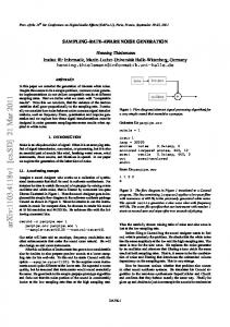
Fig. I shows the transfer function model of interconnected
order to take effect of the GRC in the simulations, most of
reheat thermal system including GDB and GRC constraints.
papers
a
The block descriptions of reheat thermal plants are shown on
nonlinear closed loop model [2, 12, 13]. In [7], LFC of
replace
linear
model
of
thermal
turbine
with
Fig. 1. The system parameters are given in TABLE I. The
interconnected reheat thermal power system considering GOB
GRC of thermal units can be modeled in either closed loop or
and GRC nonlinearities is investigated in which the GRC is
open loop method. Here, the value of GRC for reheat thermal
simulated by the closed loop model. The authors in [14], adopt
units is considered as 10%/min, i.e.:
an anti-GRC structure to overcome the negative effects of
lM,h 1= 0.1 ( "%;n) = 0.0017 ('''Xcc)
GRC on frequency stability where the GRC of the thermal unit is simulated by closed loop model. In [15], GRC is taken into
(1)
Hence, The GRC for the units can be taken into account by
theoretical consideration in the LFC design procedure. In
adding two limiters , bounded by
doing so, nonlinear turbine model is used in which the closed
±O. 0017
within the turbines
in the closed loop or open loop method as shown in Fig. 2 to
loop model of GRC is applied in simulations to emulate the
restrict the generation ramp rate for the thermal plants [6, 17].
practical limit on the response of the turbine. In [16], GDB and GRC nonlinearities are taken into account simultaneously for a two-area reheat thermal units.
+
SLP 2
Thermal droop
Tps2S + 1
KrT,.S + 1 T,.S + 1 GDB transfer function
Reheat
Afz
...------i -
s
...
................................................................................................
Fig. 1. Transfer function model of interconnected thermal power system considering GOB and GRC in closed loop model
-.1�HiH%H}8�, (a)
(b) Fig. 2. GRC models: (a) Closed loop modeling (b) Open loop modeling
30
dimensional search space. To start optimization process,
The GOB is defined as the total magnitude of a sustained speed change within which there is no change in
initially
valve position of the turbine. The GOB of the 0.06%
different values of the IPSO parameters to assess if IPSO
backlash type can be linearized in terms of change and the
will fmd satisfactory results or not. The parameters of IPSO
rate of change in the speed. In this paper, following most
algorithm should be selected carefully to provide high
model are N]=0.8 and N2=-0.2ln , respectively. Droop of
Rth. T,g Tt
OJ
K, T, Tps/, Tps2 Kp,]. Kp,2 T/2 Bfo B2
10.2 sec 11.49 sec 68.9655 0.0433 0.4312 ±0.0005 ±6 IlJi. Ilj, IlP/] N]=0.8, N]=-0.2/n
B.
been
performed
with
Cl =c2=2; y = O. I ; tmax =30; CR=0.6, where
optimized;
COmax, COmin are the initial and final inertia weights;
c],
Description System frequency Speed regulation parameter (Hz/puMW) Governor time constant of steam turbine Steam turbine time constant Steam turbine reheat constant Steam turbine reheat time constant Power system time constants Power system gains (HzlpuMW) Synchronizing coefficient Frequency bias coefficients Positive and negative ramp rates Area frequency deviations Tie-line power deviation Fourier coefficients of GDB transfer function
n= 30; m=3; COmin=O.4; n is the
comax=0.9;
population size;
PARAMETERS OF THE INTERCONNECTED POWER SYSTEM
Value 50 Hz 2 0.06 sec OJ sec
have
based IPSO program are selected as:
thermal units is set at 4%.
Parameter f
executions
performance. The parameters of our written MATLAB
recent paper [18], NJ and N2 in the GDB transfer function
TABLE I.
some
m
is total number of parameters to be
C2 are acceleration coefficients; y is a chosen number in
interval (0, 1) to control the maximum velocity vector; tmax is total number of the iterations; and CR is crossover rate. III. A.
SIMULATION RESULTS AND DISCUSSES
Simulation of reheat thermal power system considering open loop and closed loop models ofGRC In this case, the time domain simulations are realized for
O.Olpu SLP in area 1 applying GRC in the open loop model. The proposed IPSO algorithm is repeated many times to solve
the
optimization
problem.
Some
near
optimal
solutions for nominal system parameters obtained after numerous runs are shown in TABLE II. The solution with
Objective functionfor controller design
minimum value of the ITSE index is chosen as final
In order to damp effectively the oscillations, considering
optimized parameters of the controller which is highlighted
a suitable objective function is very important to find the
in TABLE II. It is noteworthy to say that the running time
controller parameters. In this work, the integral of time
of the IPSO algorithm with application of the open loop
multiplied
GRC model is very longer than the simulation time for the
squared
error (ITSE)
performance
index
is
closed loop GRC model. The damping measures such as
considered as the objective function as following:
ITSE
=
[
rTslm o t 11J;2 + M22 J
where
T'im
+
M�� ]dt
settling time
(2)
denotes the simulation time. The ITSE index
frequencies and tie-line power oscillation responses.
large oscillations and penalize long settling time. The ITSE
TABLE II.
performance index has been employed recently in [18, 19] to design AGC of interconnected power systems. In order to design LFC, an optimization problem is solved by improved
00
.2
particle swarm optimization (IPSO) algorithm to minimize