JOURNAL OF COMPUTING, VOLUME 3, ISSUE 5, MAY 2011, ISSN 2151-9617 HTTPS://SITES.GOOGLE.COM/SITE/JOURNALOFCOMPUTING/ WWW.JOURNALOFCOMPUTING.ORG
1
Architectural Development and Functional Verification of SuperSpeed USB 3.0 PHY Layer Controller Hasan Baig and Jeong-A Lee* Abstract— Universal serial bus has supported a wide variety of devices from keyboard, mouse, flash memory device, game peripheral, imaging up to high speed broad band devices. In addition, user applications demand a higher performance connection between the PC and other increasingly sophisticated peripherals. USB 3.0 addresses this need by adding even faster transfer rates. It promises a data transfer rate of 4.8 Gbps as compared to its predecessor interface USB 2.0 which has a raw data rate at 480Mbps. This implementation of synthesizable Media Access (MAC) layer of SuperSpeed USB Memory Device, with a pipelining concept of processing the packets, is proposed to support high speed transfer rate and high throughputs. Alongside, the use of efficient handshaking signals complies with optimum performance of the overall device. Master controller has also been implemented to have a command over MAC Layer and the other layers that will be implemented in a future research. This implementation meets the required specifications and ensures the data rate of atleast 4.0Gbps [1]. Index Terms— USB 3.0, MAC Layer, Physical Layer Controller, FPGA.
—————————— ——————————
1 INTRODUCTION
T
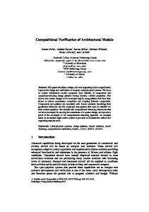
he physical layer classifies the PHY portion of a port and the physical connection between a downstream facing port (on a host or hub) and an upstream facing port on a device. The SuperSpeed physical connection is comprised of two differential data pairs, a transmit path and a receive path (Fig. 1). The electrical aspects of each path are characterized as a transmitter, channel, and receiver; these collectively represent a unidirectional differential link. Each differential link is AC-coupled with the capacitors located on the transmitter side of the differential link. The channel includes the electrical characteristics of the cables and connectors [1]. At an electrical level, each differential link is initialized by enabling its receiver termination. The transmitter is responsible for detecting the far end receiver termination as an indicator of a bus connection and informing the link layer so the connect status can be factored into link operation and management. When receiver termination is present but no signaling is occurring on the differential link, it is considered to be in the electrical idle state. When in this state, Low Frequency Periodic Signaling (LFPS) is used to signal initialization and power management information. The LFPS is relatively simple to generate and detect and uses ————————————————
Hasan Baig is with the Chosun University, Gwangju, South Korea, 501759. E-mail:
[email protected], www.hasanbaig.webs.com Jeong-A Lee *(corresponding author) is with the Chosun University, Gwangju, South Korea, 501-759. E-mail:
[email protected]
very little power. The USB PHY Layer (PHY Chip depicted in Fig. 1) handles the low level USB protocol and signaling. This includes features such as; data serialization and deserialization, 8b/10b encoding, analog buffers, elastic buffers and receiver detection. The primary focus of this block is to shift the clock domain of the data from the USB rate to one that is compatible with the general logic in the ASIC [1].
Fig 1: PHY/MAC Interface.
2 MAC INTERFACES Since the PIPE (PHY Interface for the PCI Express) is implemented for USB mode that supports 5.0GT/s, we have chosen 32 bits data paths with PCLK running at 125MHz [2]. The MAC Layer commands the communication of PHY Layer with the Link Layer and LTSSM (Link Training and Status State Machine).
© 2011 Journal of Computing Press, NY, USA, ISSN 2151-9617 http://sites.google.com/site/journalofcomputing/
JOURNAL OF COMPUTING, VOLUME 3, ISSUE 2, FEBRUARY 2011, ISSN 2151-9617 HTTPS://SITES.GOOGLE.COM/SITE/JOURNALOFCOMPUTING/ WWW.JOURNALOFCOMPUTING.ORG
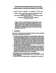
PHY layer controller itself is commanded by Master Controller. The top level block diagram of MAC Layer (or Physical Layer Controller)1 is shown in Fig. 2. It can be observed that the PHY Layer Controller itself comprises of some internal modules that will be described later in the following sub sections. The MAC layer of USB 3.0 device interacts with Link layer, LTSSM and is commanded by Master controller. LTSSM and Link Layer are beyond the scope of this research paper, so will be described briefly in the next sub sections.
2
2.1 Link Layer A Super Speed link is a physical and logical connection between two ports, called link partners. A port has a physical part and a logical part. The link layer identifies the logical portion of a port and the communications between link partners. The main responsibility of link layer is to ensure the successful data transfer with the link partner and to maintain connectivity between them.
Phy Layer Controller is also called Media Access (MAC) Layer. We will use these terms interchangeably throughout this paper.
1
Fig 2: Top Level Block Diagram of PHY Layer Controller.
JOURNAL OF COMPUTING, VOLUME 3, ISSUE 2, FEBRUARY 2011, ISSN 2151-9617 HTTPS://SITES.GOOGLE.COM/SITE/JOURNALOFCOMPUTING/ WWW.JOURNALOFCOMPUTING.ORG
2.2 Link Training and Status State Machine The Link Training and Status State Machine (LTSSM) behaves as a leading workhorse to maintain reliable link, highly optimized power consumptions and efficiently fast and perfect data transfer rate. It also implements various algorithms for link’s reliability preservation and is also liable to recover a link when an error arises. It is LTSSM who manages the power of a device proficiently and greatly reduces the link’s power consumption. It also voids the condition that causes the wastage of power. It co-ordinates and converse with PHY chip, MAC Layer, Link Layer and Master Controller to perform it’s duties.
3
later with Link Layer, Protocol Layer and LTSSM, which would be in fact a future enhancement of this research. Top level block diagram of Master Controller is shown in Fig. 3.
3.1 Decoding Path Controller The decoding process is to take packet from the PHY chip and pass it to link layer controller (decoder) and so forth. Master controller follows the protocols in the sequence mentioned below.
2.3 Dual Port Reference Memory USB 3.0 specification [1] provides a complex hardware implication. It has been emphasized to produce such an architecture that can be easily comprehended, incorporated and implemented without an extraordinary knowledge of interfacing other layer in USB 3.0 device. To achieve this, each layer is kept separated from the other by inserting dual-port-memories (Fig. 2) in between two successive layers. When one of the layers is done with writing data to intermediate memory (dual-portmemory), there is a primary need of notifiying the next concerned layer to begin execution and process the valid memory contents in the intermediate memory area. This need is accomplished by using the Master Controller which schedules the execution of layers in a predetermined sequence which is described in next section.
2.4 Buffer Interfaces The primary reason of using buffer interfaces (Fig. 2) is to overcome the need of incorporating a memory controller into a layer’s main controller. In case, for example, if MAC layer is instructed to start processing some valid memory contents, there could be two possibilities – First MAC layer fetch the memory contents by issuing address & data to enable ports of the memory with incrementing each time the address for the next valid data and asserting the enable ports. Second possiblity is that it has a separate module which is notified of the number of bytes to be fetched from memory and which is resposible of incrementing the address each time it gets valid data for memory. In order to simplify the implementation, it is recommended to have separate entities so that hardware can be easily comprehended and debugged or in another words the main controller will remain free from some extra burden while dealing with the memory. Second approach is quite better. Thus buffer interface (or memory controllers) are used in the architecture just beside intermdiate dual-port-memories.
3 MASTER CONTROLLER Master Controller is developed to command the communication flow between each module. The centralized master controller monitors and controls the decoding and encoding operation separately. It has been designed in such a way that it can easily be integrated
Fig. 3: Top Level Block Diagram of Master Controller - showing IO interface with each layer and LTSSM.
1.
When Phy Layer Decoder (Fig. 2) receives the complete packet, it generates an indication signal to master controller which in turn initializes the Link Layer (LL) decoder, provided that LL decoder is not already in a busy state. Meanwhile, master controller also sends the packet size to the LL decoder that it received from the Phy Layer decoder at the complete reception of packet.
2.
When the packet is processed by the LL decoder, it generates an indication signal to master controller which in turn initializes the Protocol Layer (PL) decoder, provided that it is not already busy. Link layer decoder de-assembles the packet received and sends the new packet size (packet size changes after passing through the packet de-assembler) to master controller. Master then sends this new packet size to protocol layer decoder at the time of its initialization.
Fig. 4 depicts the timing diagram of decoding process. Note: Master must deassert the initializing signal of Link Layer and Protocol Layer decoders as soon as they acknowledged.
JOURNAL OF COMPUTING, VOLUME 3, ISSUE 2, FEBRUARY 2011, ISSN 2151-9617 HTTPS://SITES.GOOGLE.COM/SITE/JOURNALOFCOMPUTING/ WWW.JOURNALOFCOMPUTING.ORG
4
Fig. 4: Timing diagram of decoding path controller.
3.2 Encoding Path Controller The controlling protocols, mentioned below, are followed by the master controller in order to encode the packet 1.
2.
Protocol Layer (PL) Encoder is initialized when master-configuration valid signal is received by the Master controller provided that the PL encoder must not already busy. As soon as the complete packet is encoded, PL encoder generates an indicating signal (“pl_enc_done”, Fig. 3) to the master informing it the packet has been transferred into the buffer and ready to be fetched by Link Layer controller. Master controller then generates a signal to initialize the Link Layer (LL) encoder, provided that LL encoder is not already in a busy state. Meanwhile, master also sends the packet size to the Link Layer encoder; it had received from the PL encoder at the complete reception of packet. After processing, assembling and transferring the complete packet in the buffer, LL encoder generates an indication signal (“ll_enc_done”, Fig. 3) to master controller which in turn initializes the Phy Layer encoder, provided that it is not already busy. Link layer encoder also sends the new packet size (packet size changes after passing through the packet assembler) to master controller. Master controller then sends this new packet size to Phy layer encoder at the time of its initialization.
Master controller must deassert the initializing signal of Protocol Layer, Link Layer and Phy Layer Encoders as soon as they acknowledged. Fig. 5 depicts the timing diagram of encoding process.
Note: Master must deassert the initializing signal of Protocol Layer, Link Layer and Phy Layer Encoders as soon as they acknowledged.
4 INTERFACE SIGNALS 4.1 MAC – LTSSM Interface Signals The MAC – LTSSM I/O signals are described in the Table 1. The signals described as inputs are received by MAC and those described as outputs are driven by MAC.
4.2 MAC – Master Controller Interface Signals The signals used to monitor and control the PHY Layer Controller are described in the Table 2. The signals are described from the perspective of Master Controller. Thus the signals described as “input” are received by the Master and signals described as “output” are driven by the Master.
4.3 MAC Layer Internal Signals Communication flow between intermediate modules of PHY Layer Controller is shown in Fig. 2. The Phy Encoder – Read Buffer interface signals and Phy Decoder – Write Buffer interface signals are described in the Table 3. The signals described here are from the perspective of Phy Encoder and Phy Decoder. Thus a signal described as an “output” is driven by Phy Encoder/Decoder and the signal described as an “input” is received by the Phy Encoder/Decoder.
4.4 MAC – PHY Interface Signals The MAC-PHY input and output signals are described in the Table 4. The signals described here and later are defined from the perspective of a PHY Layer Controller (MAC Layer). Thus a signal described as an “output” is driven by MAC and the signal described as an “input” is received by the MAC.
JOURNAL OF COMPUTING, VOLUME 3, ISSUE 2, FEBRUARY 2011, ISSN 2151-9617 HTTPS://SITES.GOOGLE.COM/SITE/JOURNALOFCOMPUTING/ WWW.JOURNALOFCOMPUTING.ORG
5
Fig. 5: Timing diagram of encoding path controller.
TABLE 1 MAC – LTSSM I/O INTERFACE SIGNALS
Name
Direction
Active Level
[1:0] PowerDownLTSSM
Input
N/A
transmit_LFPS
Input
High
transmit
Input
High
receiver_DO
Input
High
[2:0] Rx_status_2LTSSM
Output
N/A
LTSSM_phy_status
Output
High
do_rx_termination
Input
High
VBUS LFPS_detected
Output Output
High High
4.5 MAC – Link Layer Controller Interface Signals The MAC-Link Layer Controller I/O signals are described in the Table 5. The signals described as inputs are received by MAC and those described as outputs are driven by MAC. DPRF (for Encoder) is used by the Link Layer Controller to write the data in dual port memory.
Description Instruction for MAC to take PHY chip into the Power State (P0, P1, P2 or P3) mentioned by LTSSM. Instruction for MAC to transmit Low Frequency Periodic Signaling (LFPS) when the PHY is in P1, P2 or P3 state. Instruction for MAC to begin transmission operation followed by the proper protocols. Instruction for MAC to do receiver detection operation. Sends encoded receiver status to LTSSM. Informs LTSSM the completion of several PHY functions including power management, state transitions, rate change, and receiver detection. Controls the presence of receiver terminations commanded by LTSSM. Indicates the presence of VBUS to LTSSM Indicates LTSSM that Low Frequency Periodic Signaling (LFPS) is being detected.
That data is read and send (to PHY chip) by the Read Buffer Interface and Phy Encoder respectively (See Fig. 2). Similarly, the data coming from the PHY chip is received by Phy decoder, and then written into DPRF (for Decoder) through the Write Buffer Interface, which is then used by Link Layer Controller (See Fig. 2).
JOURNAL OF COMPUTING, VOLUME 3, ISSUE 2, FEBRUARY 2011, ISSN 2151-9617 HTTPS://SITES.GOOGLE.COM/SITE/JOURNALOFCOMPUTING/ WWW.JOURNALOFCOMPUTING.ORG
6
TABLE 2 MAC – MASTER CONTROLLER I/O INTERFACE SIGNALS
Name clk
Direction Input
Active Level N/A
done
Input
High
phy_active_tx rx_done
Input Input
High High
phy_active_rx
Input
High
[10:0]packet_size
Input
N/A
[8:0] pld_base_addr
Input
N/A
[8:0] pld_base_addr_en
Output
N/A
[10:0] pack_size
Output
N/A
reset_n start_en
Output Output
Low High
Description Pclk coming from PHY chip. Asserts after a complete transaction of packet from Read Buffer interface to PHY chip. Indicates that Encoder is active and fetching data from Read Buffer interface. Informs the Master controller that one packet has been fetched from PHY chip. Indicates that decoder is in active state and reading data from PHY chip. Size of packet (calculated by Phy Decoder) received from the PHY chip. Base address of next packet generated by Phy decoder. Base address from which Phy Encoder needs to read data. Instruct Phy Encoder to fetch the given size of packet. Master reset Starts encoding operation.
TABLE 3 MAC INTERNAL SIGNALS
Name ready_en
Direction Output
Active Level High
ack_en
Input
High
[31:0]rd_data
Input
N/A
EOP
Input
High
valid
Input
High
buf_if_active_en
Input
High
phy_rd_valid
Output
High
ready_de
Output
High
[31:0]phy_wr_data_bus phy_data_last buf_if_active_de
Output Output Input
N/A High High
ack_de
Input
High
Description Signal used to inquire the Read Buffer Interface whether it is ready to send data to Phy Encoder. Acknowledgment of “ready_en” signal from Read Buffer interface. 32-bits data bus used to fetch data from Read Buffer Interface. End Of Packet: indicates last packet from Read Buffer interface. Indicates valid data at “rd_data” bus of Read Buffer interface It signifies that Read Buffer is in active state and fetching data from dprf. Indicates valid data, at 32-bits RxData bus, to Write Buffer Interface. Signal used to inquire the Write Buffer Interface whether it is ready to receive data from Phy Decoder. 32-bits data bus; used to write data into Write Buffer interface. Indicates last packet from PHY chip It signifies that Write Buffer is in active state and writing data into dprf. Acknowledgment of “ready_de” signal from Write Buffer interface.
JOURNAL OF COMPUTING, VOLUME 3, ISSUE 2, FEBRUARY 2011, ISSN 2151-9617 HTTPS://SITES.GOOGLE.COM/SITE/JOURNALOFCOMPUTING/ WWW.JOURNALOFCOMPUTING.ORG
7
TABLE 4 MAC-PHY I/O INTERFACE SIGNALS
Name
Encoder
Direction
Active Level
[31:0]Txdata
Output
N/A
[3:0]TxdataK
Output
N/A
TxDetectRx
Output
High
Tx_elec_idle
Output
High
[1:0] PowerDown
Output
N/A
phy_status
Input
High
[2:0]Rx_status
Input
N/A
[31:0]RxData
Input
N/A
[3:0]RxDataK
Input
N/A
reset_rx_tx
Output
Low
RxPolarity
Output
High
RX_Termination
Output
High
RxValid
Input
High
Rx_elec_idle
Input
High
PowerPresent
Input
High
PCLK
Input
Rising Edge
Phy_mode
Output
N/A
Decoder
External Signals
Description Parallel USB data output bus. 32 bits represents the 4 symbols of transmit data. Bits [7:0] are the first symbol to be transmitted, and bits [31:24] are the fourth symbol. Data/Control bit for the symbols of transmitted data. For 32-bit interfaces, Bit 0 corresponds to the Low-byte of Txdata (i.e. bits [7:0]) and Bit 3 corresponds to the Upper-byte (i.e. bits [31:24]). A value of “0” indicates a Data byte and a value of “1” indicates a Control byte. Request PHY to begin a receiver detection operation. Force Tx lines to remain electrical idle when asserted in all power states. When deasserted while in P0 (as indicated by the PowerDownLTSSM signals) indicates a valid data is present on Txdata and TxdataK lines and must be transmitted. Power up or down the transceiver power states. Used to communicate completion of several PHY functions including power management state transitions, rate change, and receiver detection. Encodes receiver status and error codes for the received data stream when receiving data. Receiver is detected when Rx_status = 011. Parallel USB data input bus. 32 bits represents the 4 symbols of received data. Bits [7:0] are the first symbol to be received, and bits [31:24] are the fourth symbol. Data/Control bit for the symbols of received data. For 32-bit interfaces, Bit 0 corresponds to the Low-byte of RxData (i.e. bits [7:0]) and Bit 3 corresponds to the Upper-byte (i.e. bits [31:24]). A value of “0” indicates a Data byte and a value of “1” indicates a Control byte. Resets the transmitter and receiver Instructs PHY to perform a polarity inversion on the received data: 0: PHY doesn’t invert polarity 1: PHY does polarity inversion Control the presence of receiver terminations: 0: Terminations removed 1: Terminations present Indicates valid data on RxData and RxDataK Indicates receiver detection of an electrical idle. While deasserted with PHY in P0, P1, P2 or P3 indicates the detection of LFPS [1]. Indicates the presence of VBUS. Parallel interface differential data clock. All data movement across the parallel data interface is synchronized to this clock which operated at 125MHz (in USB case). Selects PHY operating mode 0: PCI Express 1: USB Mode So it should always be kept High.
JOURNAL OF COMPUTING, VOLUME 3, ISSUE 2, FEBRUARY 2011, ISSN 2151-9617 HTTPS://SITES.GOOGLE.COM/SITE/JOURNALOFCOMPUTING/ WWW.JOURNALOFCOMPUTING.ORG
8
TABLE 5 MAC – LINK LAYER CONTROLLER I/O INTERFACE SIGNALS
Name [8:0]ll_wr_dprf_addr
Direction Input
Active Level N/A
[31:0]ll_wr_dprf_din [31:0]ll_wr_dprf_wem ll_wr_dprf_en [8:0]ll_rd_dprf_addr
Input Input Input Input
N/A N/A High N/A
ll_rd_dprf_en [31:0]ll_rd_dprf_dout Ignore
Input Output Input
High N/A High
lrty_found
Output
High
5 MEDIA ACCESS (MAC) LAYER OR PHYSICAL LAYER CONTROLLER The main object of this research is the implementation of MAC Layer encoder and decoder that runs in parallel and hence ensures the concurrent in-out transaction of USB 3.0 protocols. Before discussing the developed algorithm of MAC Encoder and Decoder, it is good to have a look at the standard USB 3.0 packet [1] first. It is also portrayed in Fig. 6. Refer [1] for detailed description of packet symbols.
Fig. 6: Standard USB 3.0 packet with maximum of 1024 data bytes
5.1 MAC Layer Encoder (Phy Encoder) It is recommended to refer [2] first for PHY Chip encoding signals, in order to understand Phy Encoding algorithm. Algorithmic State Machine Description (ASMD) of PHY Encoder is shown in Fig. 7.
Description Address from which Link Layer Controller starts writing the data in DPRF. 32-bits data input bus. Write enable mask. Enable DPRF for writing data. Address from which Link Layer Controller wants to read the data from DPRF. Enable DPRF for reading data. 32-bits data out. Force Phy Decoder to ignore the incoming packet of data until lrty is found. Informs the Link Layer Controller that header packet is resending.
When an encoding process is done by Link Layer controller, it asserts “ll_enc_done” (section III-B), informing master controller that a valid data has been placed in dual-port-memory and must be fetched by Phy Encoder. Master controller then asserts “start_en” (Fig. 3) signal to initialize Phy encoder and waits for being acknowledged by Phy encoder. LTSSM controls the power state of PHY chip through Phy Encoder. Phy chip remains idle in P1 and P3 power states [1]. In P2 state, encoder waits for the instruction from LTSSM either to force Phy Chip to transmit LFPS [1] or to do receiver detection operation (Fig. 7). When a valid data is present in the buffers, LTSSM instructs Phy Encoder to take Phy chip into P0 state. Encoder starts the process of fetching data, from buffer, only when a positive edge of “transmit” is seen asserted. When LTSSM asserts “transmit” signal, encoder requests the data and waits for the acknowledgment from Read Buffer Interface. When transaction begins, encoder obtains the data payload size from the packet size (given by master controller, in terms of bytes) and puts into the register, named “data_pld_size”. The purpose of calculating the data payload size is to find out how many number of transactions are required to send the complete packet to Phy chip. Since each transaction can have 4 symbols of transmit data (32-bit bus) [refer 1 for detailed description], therefore a packet size is divided by 4 to obtain the correct number of transactions required. Referring [2], TxDataK bus indicates Control or Data byte in a current transaction. The RTL of encoder is efficient enough to locate which byte is a control byte or data byte in a current transaction. Fig.4 depicts that there are two such transactions (1st and 6th) which have complete control symbols (bytes) in it. The last transaction should have all control bytes, but it depends on the data payload size. If data payload size is not a multiple of 4, then there must be an ambiguity which symbol is a control or a data byte, in 2nd last transaction. Two least significant bits of “data_pld_size” indicates the position of data byte in 2nd last transaction (Fig.6).
JOURNAL OF COMPUTING, VOLUME 3, ISSUE 2, FEBRUARY 2011, ISSN 2151-9617 HTTPS://SITES.GOOGLE.COM/SITE/JOURNALOFCOMPUTING/ WWW.JOURNALOFCOMPUTING.ORG
5.2 MAC Layer Decoder (Phy Decoder) Decoding process is pretty complicated and a challenging task. It is recommended to refer [2] to grasp the PHY Chip decoding signals. ASMD of Phy Decoder is shown in Fig. 8.
9
“PowerState” of Phy Decoder is again in a control of LTSSM. Phy Decoder remains idle in P1 & P2 states. In P3, LTSSM asserts “receiver_DO” (See Fig. 2) signal when it requires “receiver detection” operation to be performed.
Fig. 7: ASMD of Phy Encoder (see Fig. 2 for block level diagram)
JOURNAL OF COMPUTING, VOLUME 3, ISSUE 2, FEBRUARY 2011, ISSN 2151-9617 HTTPS://SITES.GOOGLE.COM/SITE/JOURNALOFCOMPUTING/ WWW.JOURNALOFCOMPUTING.ORG
Phy Decoder in-turn asserts “TxDetectRx” signal [2], requesting PHY chip to begin “receiver detection” operation. This signal should remain high until “phy_status” signal [2] from Phy Chip is seen asserted. When the receiver detection operation is completed, PHY chip asserts “phy_status” signal [2]. Phy decoder then deasserts “TxDetectRx”, meanwhile informs LTSSM, the status of receiver through “Rx_status_2LTSSM” bus.
10
As soon as LTSSM instructs Phy decoder to take PHY Chip into the power state P0, decoder starts looking for “Rx_elec_idle” signal. Phy Decoder informs the LTSSM about LFPS on the basis of “Rx_elec_idle” signal. It then goes into “idle” state until valid data is present at “RxData” bus. When the valid data is present, decoder interrogates the “Write Buffer Interface” (Fig. 2) whether it is ready to accept the incoming data, and jumps to the “ackldg” (acknowledge) state.
.
Fig. 8:ASMD of Phy Decoder (see Fig. 2 for block level diagram)
JOURNAL OF COMPUTING, VOLUME 3, ISSUE 2, FEBRUARY 2011, ISSN 2151-9617 HTTPS://SITES.GOOGLE.COM/SITE/JOURNALOFCOMPUTING/ WWW.JOURNALOFCOMPUTING.ORG
It then waits for the acknowledgment from “Write Buffer Interface”. As soon as the buffer acknowledges, decoder starts fetching and sending data from Phy Chip to Write Buffer Interface respectively (Fig. 2). Phy Decoder keeps on transferring packet from Phy Chip to Write Buffer Interface unless the Link Layer Controller asserts “ignore” signal. When “ignore” is seen asserted, Phy decoder discards the incoming data from the Phy Chip and starts looking for LRTY [1]. Phy Decoder also calculates the size of packet while transferring data from Phy chip to Write Buffer interface. Fig. 4 depicts that a packet can have a maximum size of up to 1024 bytes (max data payload) + 28 bytes (standard protocol of each packet). The packet size is calculated in such a way that a counter is incremented each time a transaction occurs. Decoder continuously monitors RxDataK lines. Control byte is indicated by RxDataK bus whenever its value is non-zero. Whenever a non-zero value is present at RxDataK lines, another separated counter is incremented to monitor the number of control byte transactions. Referring to the Fig. 4, it can be observed that there could only be 3 or 4 such transactions which have control bytes in it, i.e. the first transaction, the sixth transaction and the last transaction. There could be fourth control byte transaction when data payload size is not a multiple of 4 (i.e. first three of the last four control bytes can be a part of second last transaction). Since the first and the sixth transaction is a complete control byte transaction, therefore one doesn’t need to care about them. The problem arises after data pay load due to variations in the data payload sizes. ASMD shown in Fig. 6 depicts that decoder repeatedly checks for “rxdataK_count” to become equal to 2. When “rxdataK_count” become equal to 2, decoder checks the value of RxDataK. RxDataK = 4’hF point towards that all the four bytes are control bytes and a current transaction is End of Packet. RxDataK, other than 4’hF, clearly indicates that the data payload size is not a multiple of 4 and the present transaction contains the data byte(s) along with the control byte(s). Also we would have fourth control byte transaction. If RxDataK = 4’h8 (4’b1000), it shows, there are 3 data bytes and 1 control byte. This one control byte is actually from the four of the last control bytes (shown in Fig. 4). This means that there will be only 3 (remaining) control bytes in the next transaction and the last byte will remain empty, thus a value of 1’b1 is subtracted from the size of packet (shown in Fig. 6). Similar method is implemented for RxDataK = 4’hC and 4’hE.
6 HARDWARE UTILIZATION The RTL designs of both PHY Layer and Master Controllers are fully synthesized using Virtex-5 XC5VLX110T device. The resource utilization by PHY Layer Controller and Master Controller are presented in Table 6 and Table 7 respectively.
11
TABLE 6 RESOURCE UTILIZATION BY PHY LAYER CONTROLLER
Resources Register LUT Slice
Used 108 222 116
Available 69120 69120 17280
Utilization 0.15% 0.32% 0.67%
TABLE 7 RESOURCE UTILIZATION BY MASTER CONTROLLER
Resources Register LUT Slice
Used 50 51 18
Available 69120 69120 17280
Utilization 0.072% 0.073% 0.1%
7 FUNCTIONAL VERIFICATION Although the whole of the USB Device is written in synthesizable RTL code, this entity will be representing the behavior of the Host plus the behavior of the PHY Chip. It is meant only for simulation purposes and can never infer a hardware at all. It can supress the concept of separate layers and can accommodate the behavioral of the host entity and PHY Chip as a single entity which is needed to derive the MAC layer, appearing in the front-line of the upstream facing port (USB Device). Random data is generated through a testbench and inputs to MAC Layer (assuming that it is coming from Link Layer, See Fig. 1, and Fig. 2) and a pre-defined packet size for each time a simulation runs. This data is processed by Phy Encoder via dual-port-memory and read buffer interface (Fig. 2). Phy Encoder passes this data to PHY Chip (behavioral model) which loop backs that to Phy Decoder. Phy decoder remains idle unless RxValid signal (from behavioral of PHY, Fig. 2) is seen asserted. As soon as the rising edge of RxValid signal is sensed, decoder requests Write Buffer Interface to received data coming from the Host. Once it acknowledges, the Phy decoders starts fetching the data and place it on the ports facing write buffer interface which in turn place the data into the dualport-memory (Fig. 2). Meanwhile it also looks for the control bytes (on RxData bus) on the basis of which it could find out the size of packet (See Section 4.2).
8 CONCLUSION AND FUTURE WORK Since SuperSpeed protocols are intended for dual simplex transmission lines, transmitting and receiving transactions in parallel, there is an absolute need of having the architecture which support such protocols. In order to meet the requirements, separate encode and decode paths work concurrently and independently. Thus encode path is associated with packet assemblers or encoders while the decode path is associated with packet disassembler or decoders. Encode and decode paths are executed by the Master Controller State Machine to fulfill the dual simplex capability of the bus. This synthesizable implementation of MAC Layer (Physical Layer Controller) follows the latest specification
JOURNAL OF COMPUTING, VOLUME 3, ISSUE 2, FEBRUARY 2011, ISSN 2151-9617 HTTPS://SITES.GOOGLE.COM/SITE/JOURNALOFCOMPUTING/ WWW.JOURNALOFCOMPUTING.ORG
of USB 3.0. It is designed in such a way that other layers can be easily interfaced with it. Link Layer, Protocol Layer and LTSSM will be developed in future as an independent entity and
12
integrated with this layer. The future objective could be complete USB 3.0 memory device whose top level diagram is shown in Fig. 9.
Fig. 9: The overall block diagram of proposed architecture.
REFERENCES [1]. “Universal Serial Bus 3.0 Specification”, Hewlett-Packard Company, Intel Corporation, Microsoft Corporation, NEC Corporation, ST-NXP Wireless, and Texas Instruments, Revision 1.0, November 12, 2008. [2]. “PHY Interface for the PCI Express TM and USB Architectures”, Version 2.90, Intel Corporation, 2007-08. [3]. “Universal Serial Bus Specification”, Revision 2.0, April 27, 2000. [4]. “On-The-Go Supplement to the USB 2.0 Specification”, Revision 1.3, December 5, 2006. [5]. “Inter-Chip USB Supplement to the USB 2.0 Specification”, Revision 1.0, March 13, 2006. [6]. “USB System Architecture (USB 2.0)”, MindShare, Inc., Don Anderson. [7]. “eXtensible Host Controller Interface for Universal Serial Bus (xHCI)”, Revision 1.0, 2010. [8]. Peter J. Ashenden, “Digital Design: An Embedded System Approach using Verilog”, Elsevier, 2008.
Hasan Baig obtained his Bachelors of Engineering Degree (Electronics) from NED University of Engineering and Technology, Karachi, Pakistan, in January 2010. Currently he is pursuing his MS Degree in Embedded Computing from Chosun University, Gwangju, South Korea. Also, he is serving as a Research Assistant to Prof. Jeong-A Lee in computer system lab. He is a recepient of Korean Global IT Scholarship to carry out research and higher studies. He has conducted many workshops on behalf of IEEE Students branch. His research interest includes embedded system design, FPGAs, on-chip process variations estimation, partially reconfigured embedded systems. Jeong-A Lee is presently a Professor of Department of Computer Engineering, since joining Chosun University in 1995. She received the B.S. in Computer Engineering with from Seoul National University in 1982, M.S. in Computer Science from Indiana University, Bloomington in 1985 and Ph.D. in Computer Science from University of California, Los Angeles in 1990. From 1990 to 1995, she was an assistant professor at the Department of Electrical and Computer Engineering, University of Houston. Her research interests include computer architecture, fast digital and CORDIC arithmetic, application specific architectures design and configurable computing. She is the author of more than 100 technical papers, was a guest editor of a special issue on CORDIC, Journal of VLSI Signal Processing Systems for Signal, Image, and Video Technology in 2000, and has been working as a programming committee member for several international conferences and a senior member of IEEE.