IEEE TRANSACTIONS ON MAGNETICS, VOL. 46, NO. 3, MARCH 2010
837
Architecture and Implementation of a First-Generation Iterative Detection Read Channel Richard L. Galbraith1 , Travis Oenning1 , Michael Ross1 , Bruce Wilson2 , Ivana Djurdjevic2 , and Jihoon Park2 Hitachi Global Storage Technologies, Rochester, MN 55901 USA Hitachi Global Storage Technologies, San Jose, CA 95135 USA This paper explores the architecture of a first-generation iterative detection read channel solution that delivers up to an 8% increase in drive capacity compared to previous generation electronics. Using low density parity check (LDPC) coding, detected data is continually improved by a detection structure that implements multiple iterations through a set of soft-input soft-output (SISO) and message-passing (MP) blocks. A specially constructed LDPC code is used to optimize performance in the presence of inter-symbol interference (ISI). Also, Reed-Solomon error correction coding (ECC) is retained for optimal data integrity. A 65 nm technology is used in the implementation of this design. Index Terms—Iterative detection, low-density parity-check (LDPC), magnetic recording, partial-response maximum-likelihood (PRML).
I. INTRODUCTION
P
ARTIAL-RESPONSE maximum-likelihood (PRML) read channels have been used in hard disk drives since 1990 [1], [2]. PRML was a dramatic departure from the previous peak-detection technology and offered an optimal approach to account for the inter-symbol interference (ISI) present in the signal from the read head. Over the last couple of decades, there have been many incremental improvements to the basic PRML scheme. Adaptive digital filters and various linearization circuits are now standard practice for providing and maintaining correct equalization to the channel’s detection target polynomial [3], [4]. The original Viterbi detection trellises used in PRML systems contained branch metrics based on a standard Euclidean squared error computation [5]–[7]. Many modern PRML Viterbi trellises utilize per branch whitening filters, variance scaling terms and offset terms to optimize the system for media dominated noise [8]. Simple short block parity has also been exploited in many read channel designs, to increase the coding distance in an implementation friendly manner [9], [10]. In these parity encoded schemes, either parity post-processing or a super trellis structure is used to provide joint knowledge of the ISI and parity coding. The iterative detection read channel (IDRC) is the latest in signal processing advancements for the hard disk drive and maintains the PRML concepts as a foundation. Here we detail some of the architecture and implementation of a first-generation IDRC that uses a low density parity check (LDPC) type of coding. This particular IDRC design was first made available in the Hitachi Global Storage Technologies Travelstar 5K500.B 2.5-in hard disk drive [11]. A 65 nm mixed-signal
Manuscript received August 20, 2009; revised September 29, 2009 and November 03, 2009; accepted December 02, 2009. Current version published February 18, 2010. Corresponding author: R. L. Galbraith (e-mail:
[email protected]). Color versions of one or more of the figures in this paper are available online at http://ieeexplore.ieee.org. Digital Object Identifier 10.1109/TMAG.2009.2038803
Fig. 1. Three levels of coding used in IDRC data path.
CMOS technology is used to implement the system on chip (SoC) which includes the IDRC function. A fully yielded data rate of 1700 Mbps is achieved with a power consumption of 1316 mW at 1700 Mbps during full read operation. The area of the IDRC function, including both analog and digital circuits, is 5.8 mm . All digital circuits, including the Viterbi detector, were generated using logic synthesis. The rest of the paper is organized as follows. Section II describes the IDRC coding and Section III covers the iterative detection structure. In Section IV, an equalization overview is provided. Sections V and VI provide detail of the SISO and message passing blocks used in the iterative detector. Section VII describes timing recovery enhancement and Section VIII shows simulation performance results. Section IX concludes the paper. II. CODING Fig. 1 illustrates the three levels of coding used in the IDRC data path. This particular ordering of codes is a recent development in the drive industry and is referred to as reverse concatenation [12]. Older hard disk drives used a forward concatenation scheme where the modulation and Reed-Solomon code blocks are swapped. Reverse concatenation results in a more efficient coding structure and also is an enabling component for the move to iterative detection. The modulation code has rate 0.995 and only the customer data and system integrity symbols are modulation encoded. Modulation constraints are created by an algebraic method which treats the uncoded data as large base-2 numerals. A change of basis is performed by the encoder, which results in a slightly redundant number representation having specific run-length limited properties [13]. The Reed-Solomon (RS)
0018-9464/$26.00 © 2010 IEEE
838
IEEE TRANSACTIONS ON MAGNETICS, VOL. 46, NO. 3, MARCH 2010
Fig. 3. Placement of LDPC redundancy bit pairs within LDPC codeword.
Fig. 4. Proximity short cycles resulting from LDPC code and ISI coupling.
Fig. 2. Permutation matrix with punctured row and column highlighted.
check symbols and LDPC redundancy are generated from the modulated data and are then inserted in a distributed fashion throughout the sector so as to minimize disruption to the global modulation constraint. The LDPC code used is a column weight one design, where each data bit is involved in exactly one LDPC parity check equation [14]–[17]. The low distance nature of a column weight one LDPC code provides for low weight residual errors from the iterative detector. An RS error correction code can be successfully concatenated in this type of system. For a 512 byte sector format, two 1/2 sector long LDPC codewords are employed. To generate the LDPC code’s parity check matrix, a congruential method is first utilized to form a square permutation matrix . The linear congruential generator for this task is given by
where each entry in the permutation matrix has an index given . The 97-square permutation matrix is then puncby tured by removing the one row and the one column which corresponds to the sole entry located on the main diagonal of the matrix. Fig. 2 is an illustration of the matrix except with the punctured row and column still shown and highlighted, a 96-square matrix being the final result. The full parity check matrix is then based on the concate. This construction nation of powers of , method provides for very efficient LDPC encoding and message passing structures, since each set of 96 columns in the parity check matrix can be related to the subsequent set of 96 columns by a common permutation. The LDPC redundancy is grouped into 2-bit pairs and distributed at periodic intervals within the codeword as shown in Fig. 3. The LDPC redundancy is located at indexes 10,11 and 84,85 within each set of 96-bits. This is one of only a few possible periodic options given that the redundancy is desired to be in bit pairs with bit pair separation greater than or equal to 20 bits so as to not disrupt the run length constraints.
The rate of the LDPC coding is given by
thus having a redundancy overhead of approximately 4.1%. In an LDPC code with a column weight greater than one, there can exist short cycles [18]. Short cycles allow shortcuts in the information flow being performed by the message passing algorithm. This degrades performance. Using an LDPC code with a column weight equal to one, as in this design, traditional short cycles cannot exist. Instead, a variation referred to here as proximity short cycles, is an essential parameter to minimize in order to achieve good channel performance. Fig. 4 shows a toy example of a parity check matrix, and some examples of proximity short cycles. Proximity short cycles are the result of both the adjacent bit energy coupling from ISI and the LDPC code. In Fig. 4, two separate proximity short cycles are illustrated by the horizontal lines and slanted vertical lines forming a closed path. The horizontal lines represent information transfer due to the message passing function defined by LDPC code. The slanted vertical lines represent information transfer due to the SISO function defined by the channel ISI. If a short closed path is generated by the combination of these two information transfer mechanisms, a proximity short cycle is formed and performance will degrade. For perpendicular recording, ISI coupling is mainly limited to immediately adjacent bits. The minimization of proximity short cycles was of primary importance in the selection of a final LDPC code construction. In this IDRC design, each 1/2 sector long LDPC codeword contains only 3 instances of four edge proximity short cycles. III. ITERATIVE DETECTION The IDRC iterative detector structure, shown in Fig. 5, is a feed forward fixed latency 3 1/2 iteration design. Each block shown in the figure is individually instantiated. This provides a pipelined design with continuous read operation throughput. A 16-state Viterbi detector is used to provide the initial hard decisions to the first soft-input soft-output (SISO) block. The combination of the Viterbi and the first SISO block was deemed a reasonable replacement for a more complex pattern-dependent
GALBRAITH et al.: FIRST-GENERATION ITERATIVE DETECTION READ CHANNEL
839
Fig. 6. Rearrangement of linear signal path to provide Viterbi with matched filter metric input. Fig. 5. IDRC iterative detector structure.
noise-predictive soft output Viterbi design. The SISO blocks are used to generate bit log-likelihood ratio (LLR) soft information, provide improved hard decisions, and also incorporate media noise detection enhancements. The message passing (MP) block has knowledge of the LDPC code and generates extrinsic information to bias the bit LLRs. Both the SISO and MP blocks pass information between bits. The SISO block exchanges information between bits that are related to each other by proximity (ISI). The MP block exchanges information between bits that are related to each other by the parity check equations of the LDPC code. Hard decisions are improved through each of the SISO blocks with the final SISO block providing hard decisions to Reed-Solomon ECC. Power saving capability is included in the iterative detector by allowing an early stop criterion. In this case, final hard decisions may come from an intermediate SISO block. Unused detection blocks are clock gated to reduce power. A count of the unsatisfied parity check equations in the MP block is used as a measurement for early stop. IV. EQUALIZATION The samples provided to the iterative detector are equalized to a perpendicular friendly {1 2 1} target. This target has a full magnitude response at DC and has increasing attenuation as the frequency increases, exhibiting two nulls at the Nyquist frequency. An adaptive 16-tap digital finite impulse response (DFIR) filter is used to obtain the desired equalization. This equalization target is fixed regardless of recording density. Auxiliary digital filters are implemented to support recording density adjustment for the Viterbi and SISO blocks. The {1 2 1} equalization target is oriented to a matched filter metric processing scheme [19]. Using this scheme, the matched filter metric equalized signal response, as used by the detection blocks, is equivalent to the native detection target polynomial convolved with a mirrored coefficient version of itself. This matched filter metric signal always exhibits a symmetrical auto-correlation characteristic. Thus the {1 2 1} equalization
target corresponds to an equivalent native detection target of {1 1}. Use of the matched filter metric allows simplification of the Viterbi add-compare-select computation and is also exploited in the design of the auxiliary filters used by the Viterbi and SISO blocks [20], [21]. The 16-state Viterbi detector is constructed with trellis branch transformations such that a matched filter metric input signal is expected. Fig. 6 illustrates the rearrangement of the linear signal terms such that the Viterbi detector effectively implements a native target polynomial containing a DC null, Nyquist null, and a two parameter whitening polynomial. The original fractional and used in the whitening polynomial are coefficients replaced in the reconfiguration shown by Fig. 6 by two integer coefficients “a” and “b” which allow the Viterbi detector to be optimized for recording density and noise environment. The SISO block implements many error event filters which each calculate the cost of an alternate sequence compared to the currently defined hard decision path. The {1 2 1} equalized signal could be used directly with these error event filters, but a desire to have a detection system with insensitivity to DC and immune to observed low frequency 1/f noise components was thought important. To achieve this aim, a long auxiliary filter was implemented that maintains close to optimal perpendicular response, provides a one parameter adjustment for recording density, and also includes a DC null. Fig. 7 illustrates the tap weight coefficients for this 43-tap auxiliary digital filter which is driven by the 16-tap equalization DFIR. The integer “f” parameter in this auxiliary filter can be set negatively to adjust for lower recording density, or positively for higher recording density. Since most of the coefficients for this auxiliary filter are unity, the implementation can contain very few multipliers. The overall native target response as seen by the SISO block is illustrated in Fig. 8. This is compared to a reference magnitude response for the {1 1} target. V. SOFT-INPUT SOFT-OUTPUT OPERATION Each of the SISO blocks contains two banks of error event filters as their major computational elements. These filter banks
840
IEEE TRANSACTIONS ON MAGNETICS, VOL. 46, NO. 3, MARCH 2010
Fig. 7. Illustration of tap weight coefficients for SISO auxiliary filter.
Fig. 9. Error event filter banks used in LLR soft information generation. Fig. 8. Native equivalent SISO target compared to {1 1} target response.
aid in finding the best sequence costs for each bit equal to and . The difference of these costs generates the bit LLR soft information values [22], [23]. The error event filters use the latest hard decisions as a reference and also incorporate the LLR extrinsic biases from the previous MP block. An error event represents a proposed change to the current hard decision sequence. A three valued convention ( , , 0) bit changing value from 0-to-1, 1-to-0, or corresponds to an staying the same. Each error event pattern has both a positive and negative representation. One of these two polarities is always disallowed by the hard decision sequence context. This fact is used to simplify the implementation by allowing each error event filter to selectively calculate only one of the two error event polarities. Additionally, each error event pattern may or may not be valid at a given time index , depending on the pattern matching context with the hard decision sequence. The output polarity convention for an error event filter is positive to indicate the improvement in cost for the proposed change in sequence, and negative to indicate the degradation in cost for the proposed change in sequence. Fig. 9 illustrates the two banks of error event filters. One bank , contains a list of error events that flip the of filters, labeled hard decision at bit index . The second bank of filters, labeled , contains a list of error events that retain the hard decision at bit index . The computation for each bit LLR is given by
and represent the positive valued imwhere each provement or negative valued degradation in cost of the proposed sequence change. It should be noted that there is also a zero value included in the maximum calculation for the error events that retain the hard decision value. This zero value is representative of the hard decision reference path and thus does not allow the second maximum calculation to attain a negative value. Lastly, hard decision ’s are updated according to the ’s. sign of the corresponding The two banks of error event filters attempt to ensure that the best sequence costs are used in the bit LLR difference computation. The list of error events shown in Fig. 9 should not be considered universally optimal. The optimal list could turn out quite differently depending on the channel model assumed. The iterative detection system is very effective at correcting longer error events in the first or second iteration, since these error events are involved in a larger number of parity check equations. To minimize implementation size, a portion of the longer error event filters are removed from the filter banks for the SISO blocks used in the ending iterations. An additional enhancement to the bit LLR computation is the use of context dependent biasing of the error event filters [24]. This biasing technique has a very significant performance improvement in the presence of transition dominated media noise. With this technique, an individualized offset can be applied to the output of each error event filter based on the following rule as illustrated in Table I. This scheme is based on the observation that errors in the detected sequence are likely to cause an apparent decrease in the number of transitions as compared to the correct sequence. The decision boundaries for error events are effectively moved
GALBRAITH et al.: FIRST-GENERATION ITERATIVE DETECTION READ CHANNEL
TABLE I CONTEXT DEPENDENT BIASING RULE
Fig. 10. MP block diagram.
by the offsets applied to the error event filter outputs, to account for the unequal size of the noise clouds under the media noise condition. VI. MESSAGE PASSING OPERATION The function of the MP block is to generate extrinsic information for each bit in an LDPC codeword. This extrinsic information will provide a bias to help correct bits in error and also reinforce bits that are already correct. The procedure used to implement this function is the well known Min-Sum algorithm [25], [26]. Only basic add, compare, and select operations are needed for implementation. In this particular IDRC design, each LDPC codeword constitutes 96 parity check equations. Each parity check equation relates 24 to 25 pseudo randomly spaced bits by a simple even parity. For each of these parity related sets of bits, the MP block implements a bit-to-check and check-to-bit algorithm that produces the extrinsic information. A block diagram of the MP function is illustrated in Fig. 10. The bit-to-check step can be viewed as an information-gathering function. Using the sign of each bit’s LLR, the parity check equation is checked to be satisfied or not satisfied. Also identified are the LLR magnitudes for the least and second least reliable bits, along with the location of the least reliable bit. The check-to-bit step is used to generate the extrinsic output for the MP block. If the parity check equation is satisfied, the extrinsic information will have a polarity that confirms the current hard decision value for each of the bits. If the parity check equation is not satisfied, the extrinsic information will have a polarity that attempts to flip the current hard decision value for each of the bits. The extrinsic information will have a magnitude proportional to the least reliable bit LLR, except for the bit index corresponding to the least reliable bit, which will have a magnitude proportional to the second least reliable bit LLR.
841
Fig. 11 illustrates the generation of the extrinsic information using bars to represent the sign and magnitude of the LLR values. In this toy example, the six bars at the top of the figure are to illustrate the LLRs for bits that are randomly distributed in an LDPC codeword. These bits are also assumed to be related by even parity, since they constitute one of the parity check equations of the LDPC parity check matrix. The bars in the middle of the figure demonstrate the extrinsic output corresponding to each of the six bits in the case that the parity check equation is not satisfied. In this case, the sign of the extrinsic outputs are all in a direction opposite of the LLRs at the top. This corresponds to wanting to flip the bits. Also evident are the five small magnitudes corresponding to the least reliable bit magnitude, and one larger magnitude corresponding to the second least reliable bit magnitude. The bars at the bottom of the figure are for the case that the parity check equation is satisfied. These bars are the same as the middle bars except all with opposite sign. This extrinsic output will confirm the sign of the LLRs at the top of the figure. Improved iterative detection performance can be achieved by using an attenuator as shown in Fig. 10 [27]. A value of 0.75 was found to achieve near optimal performance over a wide range of operation. A noteworthy comment is that even when the hard decisions at the output of a SISO block are error free, the parity check equations may not be fully satisfied at the following MP block. This is due to the necessity of the MP block subtracting the previous iteration extrinsic bias from the incoming SISO LLRs, and also is an attribute of using a column weight one LDPC code. VII. TIMING RECOVERY With the addition of iterative detection, synchronous timing recovery of the read back signal in poor SNR conditions must also be improved, so as not to limit the overall channel performance. Latency in the timing recovery control loops is of paramount importance. Latency degrades the phase margin and overall stability of the control loops, and an otherwise optimum feedback gain may have to be compromised to maintain stable operation. The physical latency in the loops often cannot be reduced. In fact, latency generally has to increase with each design because of pipelining delays needs to obtain the required part speed. For this IDRC design, an active latency cancellation scheme was chosen [28]. This scheme can allow the latency term in the closed-loop transfer function of the proportional control loop to vanish, greatly increasing the stability of the control loop. Unfortunately, large latencies in the data path may still allow some degradation to the overall performance since the integral correction portion of the control loop does not contain this feature. Fig. 12 illustrates a simplified view of the proportional correction section of a timing control loop. The plant represents a lumped version of the physical loop components, characterized by latency and an integration function. A simple digital model of the plant is replicated within the digital loop control logic. This plant model is used to provide a zero latency response to the applied phase correction. The plant model effectively becomes void after the physical plant response becomes available. This
842
IEEE TRANSACTIONS ON MAGNETICS, VOL. 46, NO. 3, MARCH 2010
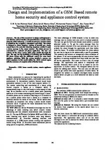
Fig. 13. SNR performance of IDRC versus previous generation.
Fig. 11. Graphical illustration for extrinsic information generation.
Fig. 12. Use of active delay cancellation in timing control loop.
feature is employed in both the acquisition and tracking timing control loops for maximum benefit. VIII. PERFORMANCE The IDRC design described in this paper achieves significant performance gain over the previous generation channel electronics used in production hard disk drives. The previous generation design was based on a Viterbi detector plus parity postprocessor (PPP) structure (100/102 parity code). Signal-to-noise ratio (SNR) gains are shown by the simulation curves of Fig. 13. This figure indicates a 0.81 dB SNR gain at 10E-5 sector failure rate using a Reed-Solomon error correction code (ECC) with correction capability for both channel designs. The ECC operates on 10-bit symbols.
The Noise mix used for the simulation constitutes 70% jitter, 20% colored noise, 5% electronic noise, and 5% width variation referenced to an all transitions pattern. The perpendicular response is based on a hyperbolic tangent model with an isolated transition response h(t) given by [29]:
where is the time width required for h(t) to rise from to . A user bit density of , where is the uncoded bit duration, was used for this simulation. Encoded is calculated from the user bit density by bit density dividing by the overall code rate. Overall code rate for the simulated 512 byte sector is defined as 4096 divided by the total encoded bits written to the disk. The PPP design in this simuwhile the IDRC design has a lation has a . The IDRC Viterbi detector target paramewhile the SISO target parameter was ters used were . Fig. 14 also demonstrates for the two designs the sector failure rate behavior using partial ECC capability. For this simulation, the SNR is held constant using the same parameters as ECC above. Though the coding redundancy is fixed for level, the sector failure rate is measured for each ECC partial correction value from 0 to 16 symbols. In order to achieve similar sector failure rate curves, the PPP design is simulated with an SNR offset by 0.8 dB compared to the IDRC design. The predictable straight line behavior of the IDRC curve, especially on the right half of the curve, confirms the lack of any error burst type behavior. Poor error burst type behavior will typically cause the curve to flatten. This corresponds to an increased capability of ECC not being effective since long error bursts are beyond the capability of the ECC. IX. CONCLUSION An overview of a first-generation IDRC design has been presented. This design has been successfully integrated into a
GALBRAITH et al.: FIRST-GENERATION ITERATIVE DETECTION READ CHANNEL
Fig. 14. Partial ECC performance at fixed SNR.
production mobile hard disk drive product. The use of column weight one LDPC coding provided a foundation for achieving an iterative design with reasonable performance gain, design simplicity, and compatibility with established RS error correction coding. Overall, this IDRC design provides up to an 8% increase in drive capacity compared to previous generation electronics. This significant drive capacity improvement comes at a cost of greater chip area and power dissipation relative to a noniterative channel design. A direct quantitative comparison is not possible since previous generation electronics were not implemented in 65 nm technology. The use of 65 nm technology was an enabling component allowing this IDRC device to meet the required cost and power requirements. As higher density integrated circuit technologies become available, more sophisticated future generation IDRC designs are sure to provide further capacity gains while maintaining cost and power targets.
REFERENCES [1] R. D. Cideciyan, F. Dolivo, R. Hermann, W. Hirt, and W. Schott, “A PRML system for digital magnetic recording,” IEEE J. Sel. Areas Commun., vol. 10, no. 1, pp. 38–56, Jan. 1992. [2] J. D. Coker, R. L. Galbraith, G. J. Kerwin, J. W. Rae, and P. A. Ziperovich, “Implementation of PRML in a rigid disk drive,” IEEE Trans. Magn., vol. 27, no. 6, pt. 2, pp. 4538–4543, Nov. 1991. [3] S. U. H. Qureshi, “Adaptive equalization,” Proc. IEEE, vol. 73, pp. 1349–1387, Sep. 1985. [4] C. S. H. Wong, J. C. Rudell, G. T. Uehara, and P. R. Gray, “A 50 MHz eight-tap adaptive equalizer for partial-response channels,” IEEE J. Solid-State Circuits, vol. 30, no. 3, pp. 228–234, Mar. 1995. [5] G. D. Forney, Jr., “The Viterbi algorithm,” Proc. IEEE, vol. 61, no. 3, pp. 268–278, Mar. 1973. [6] R. W. Wood and D. A. Petersen, “Viterbi detection of class IV partial response on a magnetic recording channel,” IEEE Trans. Commun., vol. 34, no. 5, p. 454, May 1986.
843
[7] H. K. Thapar and A. M. Patel, “A class of partial response systems for increasing storage density in magnetic recording,” IEEE Trans. Magn., vol. 23, no. 5, p. 3666, Sep. 1987. [8] J. Ashley, H. Stockmanns, and K. Zhang, “Method and Apparatus for Data-Dependent Noise Predictive Viterbi,” U.S. Patent 7 522 678, Apr. 21, 2009. [9] J. Livingston and W. Bliss, “Sampled Amplitude Read Channel Employing a Trellis Sequence Detector Matched to a Channel Code Constraint and a Post Processor for Correcting Errors in the Detected Binary Sequence Using the Signal Samples and an Error Syndrome,” U.S. Patent 6 185 173, Feb. 6, 2001. [10] R. Cideciyan, J. Coker, E. Eleftheriou, and R. Galbraith, “Noise predictive maximum likelihood detection combined with parity-based postprocessing,” IEEE Trans. Magn., vol. 37, no. 2, pp. 714–720, Mar. 2001. [11] [Online]. Available: www.hitachigst.com/tech/techlib.nsf/products/ Travelstar_5K500.B [12] W. G. Bliss, “Circuitry for performing error correction calculations on baseband encoded data to eliminate error propagation,” IBM Tech. Discl. Bull., vol. 23, pp. 4633–4634, Mar. 1981. [13] M. Blaum, R. Cideciyan, E. Eleftheiou, R. Galbraith, K. Lakovic, T. Mittelholzer, T. Oenning, and B. Wilson, “High-rate modulation codes for reverse concatenation,” IEEE Trans. Magn., vol. 43, no. 2, pt. 2, pp. 740–743, Feb. 2007. [14] R. G. Gallager, Low Density Parity Check Codes. Cambridge, MA: MIT Press, 1963. [15] M. C. Davey, “Error-Correction Using Low-Density Parity-Check Codes,” Ph.D. dissertation, Univ. Cambridge, Cambridge, U.K., Dec. 1999. [16] M.P. C. Fossorier, “Quasi-cyclic, low-density parity-check codes from circulant permutation matrices,” IEEE Trans. Inform. Theory, vol. 50, no. 8, pp. 1788–1793, 2004. [17] R. M. Tanner, D. Sridhara, and T. Fuja, “A class of group-structured LDPC codes,” in Proc. 6th ICSTA, 2001. [18] J. L. Fan, “Array codes as low-density parity-check codes,” in Proc. 2nd Int. Symp. Turbo Codes, 2000, pp. 543–546. [19] G. Ungerboeck, “Adaptive maximum-likelihood receiver for carriermodulated data-transmission systems,” IEEE Trans. Commun., vol. 22, no. 5, pp. 624–636, May 1974. [20] R. Cideciyan, D. Dholakia, E. Eleftheiou, R. Galbraith, T. Mittelholzer, and T. Oenning, “Apparatus Using a Lengthened Equalization Target Filter With a Matched Filter Metric in a Viterbi Detector,” U.S. Patent 7 286 595, Oct. 23, 2007. [21] R. Cideciyan, J. Coker, E. Eleftheiou, R. Galbraith, and D. Stanek, “Method and Apparatus for Viterbi Detection of Generalized Partial Response Signals Using Partial Matched Filter and Matched Filter Metrics,” U.S. Patent 6 377 635, Apr. 23, 2002. [22] J. C. De Souza, B. Marcus, R. New, and B. Wilson, “Soft Output Viterbi Algorithm (SOVA) With Error Filters,” U.S. Patent 6 708 308, Mar. 16, 2004. [23] I. Djurdjevic, R. Galbraith, B. Wilson, Y. X. Lee, T. Oenning, M. Blaum, K. Lakovic, and Z. Li, “Techniques for Generating Bit Reliability Information in the Post Processor,” U.S. Patent application publication 2009006930, Jan. 1, 2009. [24] R. Cideciyan, A. Dholakia, E. Eleftheriou, R. Galbraith, T. Mittelholzer, and T. Oenning, “Apparatus for Providing Data Dependent Detection in a Data Read Channel,” U.S. Patent application publication 20050078394A1, Apr. 14, 2005. [25] M. Fossorier, M. Mihaljevic, and H. Imai, “Reduced complexity iterative decoding of low density parity check codes,” IEEE Trans. Commun., vol. 47, pp. 673–680, May 1999. [26] N. Wiberg, “Codes and Decoding on General Graphs,” Ph.D. dissertation, Dept. Elec. Eng., Univ. Linköping, Linköping, Sweden, Apr. 1996. [27] C. X. Huang and A. Ghrayeb, “A simple remedy for the exaggerated extrinsic information produced by the SOVA algorithm,” IEEE Trans. Wireless Commun., vol. 5, no. 5, pp. 996–1002, May 2006. [28] K. J. Åström and T. Hägglund, PID Controllers: Theory, Design and Tuning. Research Triangle Park, NC: ISA Press, 1995. [29] H. Sawaguchi, Y. Nishida, H. Takano, and H. Aoi, “Performance analysis of modified PRML channels for perpendicular recording systems,” J. Magn. Magn. Mater., vol. 235, p. 265, 2001.