simulator is developed under requirements to utilize as much as possible the low cost commercial computer hardware and system software support. The other ...
158
IEEE Transactions on Power Delivery, Vol. 11, No. 1, January 1996 DESIGN, IMPLEMENTATION AND VALIDATION OF A REAL-TIME DIGITAL SIMULATOR FOR PROTECTION RELAY TESTING
M. Kezunovic, Senior Member J. Domaszewicz, Student Member Texas A&M University
V. Skendzic' ,Member Cooper Power Systems
M. Aganagic' Siemens Empros
J. K. Bladow, Member, S. M. McKenna D. M. Hamai Western Area Power Administration
U.S.A. Abstract - This paper presents implementation details describing a new design of a real-time digital simulator for relay testing. The simulator is developed under requirements to utilize as much as possible the low cost commercial computer hardware and system software support. The other requirements ask for a three-terminal support with extensive Graphical User Interface (GUI) and the simulation time step as low as 50ps. Such a design has been built for Western Area Power Administration (WAPA) and f U y validated using a model of an actual WAPA system section. The simulator was delivered to WAPA in March 1994.
project are also utilized in the area of instrument transformer modeling [24-271.
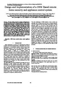
Keywords: Real-time Digital Simulator, Electromagnetic Transients Program (EMTP), Relay Testing INTRODUCTION The use of power system simulators for relay testing has been known for a long time. The well established approach is to use analog scaled power system models [1,2] or hybrid electronic simulators [3,4]. The latest trend is to use digital simulators that offer additional flexibility at a lower cost [5]. In the last ten years several digital open-loop simulators for relay testing have been constructed using low cost computers [6-1 I]. The main property of these designs was their open-loop mode of operation that could not directly support real-time interactions between the simulated power system and a relay under test. The next generation of digital simulators for relay testing is aimed at real-time operation. It has been recognized that the realtime simulation of network response during faults is computationally involved and requires powerful computer facilities [12-151. It has been proven that parallel computer architecture provides the performance required for real-time relay testing [16]. This paper reports on a new approach to real-time simulator implementation using a single processor computer for network simulation, and multiple Digital Signal Processors (DSPs) for instrument transformer and circuit breaker model implementation. The design has been optimized for power system protection device studies, and is capable of simultaneously supporting up to 3 independent test terminals. Simulator setup is shown in Figure 1. The paper concentrates on the simulator implementation and validation details while the issues related to real-time network simulation and architecture concepts have been reported separately [17-20]. This design utilizes the waveform reconstruction and power amplifier subsystems developed under a separate simulator project funded by the Electric Power Research Institute(EPRI) [21231. A number of the results published as an outcome of the EPRI
95 WM 034-9 PWRD
A paper recommended and approved by t h e IEEE Power System Relaying Committee of t h e IEEE Power Engineering S o c i e t y f o r p r e s e n t a t i o n a t t h e 1995 IEEE/PES Winter Meeting, January 29, t o February 2 , 1995, New York, NY. Manuscript submitted August 1 , 1994; made a v a i l a b l e f o r p r i n t i n g November 30, 1994.
Figure 1. Real-time Power System Simulator Equipment The paper starts with a discussion of the real-time simulator design requirements, presents the specific approach to real-time simulation and gives implementation details. Performance assessment and validation results are given at the end. REAL-TIME SIMULATOR DESIGN REQUIREMENTS Several design requirements were specified by the sponsor as well as by the research team. It was specified that the simulator must:
,
Utilize low cost commercial hardware and system software to maximum extent possible Enable adequate system modeling and fault simulation complexity Provide sufficient output signal bandwidth Support real-time interaction between the simulated power system and the external devices under test Perform reliable monitoring of real-time program execution Utilization of commercial low cost solution was extensively studied during Phase I of the project where feasibility of using commercially available parallel processing architecture was evaluated. At that time (1991) it was concluded that the readily available commercial parallel architectures were not suitable for the given application. The remaining choice was to utilize the existing high performance single processor computers for the simulator implementation. This design option has been specified as a requirement for the simulator implementation. Adequate system modeling complexity has been translated into requirements for detailed modeling of transmission lines and nonlinear elements as well as precise representation of instrument
' The work was done while the authors were with Texas A&M University 0885-8977/96/$05.00 0 1995 IEEE
159 transformers and circuit breaker responses. The fault simulation had to represent various fault events on transmission lines that can be represented with models, constant parameter (cp) models and frequency dependent (fd) parameter models. Further more, the fault waveforms had to be generated for the lines containing series capacitors with Metal Oxide Varistors (MOVs) and surge arresters. All of the faults had to be generated with up to three relay controlled circuit breakers, enabling the testing of three independent relays interacting with a given network at the same time. Output signal bandwidth is directly related to the simulation step size. As indicated in [28], precision of the power system simulation process depends on the excitation signal frequency. Error associated with the trapezoidal integration process increases as the signal frequency approaches Nyquist limit:f=f/2=1/(2t&. In order to keep the output error below =lo%, the simulation sampling frequency should be at least 10 times higher than the desired output signal bandwidth. For fundamental frequency based protection equipment testing, the required bandwidth is typically >500 Hz [29], making it necessary to perform the simulations with fs>5kHz (ts300 time steps). This means that for a given breaker model, the primary network simulation performed on the RS 6000 machine, can on average be run up to 300 samples ahead of the real-time (as seen on the simulator output). In the case of data shown in Figure 9, this means that the real-time simulation can successfully be executed with a 6 4 . 7 ~ stime step. This was verified by running an actual real-time simulation with a 6 5 p time step.
Acknowledgments This development has been funded by DOE-Westem Area Power Administration under contract FC65-90WA 07990. The authors want to acknowledge the participation of Drs. H. W. Dommel and J. Marti from the University of British Columbia, and Dr. A. Abur from the Texas A&M University in the Phase I of the project, involving the simulator feasibility study. REFERENCES
~~
~
17.8
178
17.8
9
9
9
18 15 20 30 70 80 50
18 15 20 30 70 80 50 50
18 15 20 30 70 80
50
50 50
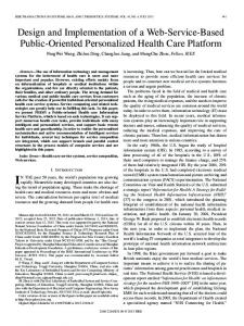
Opening Delay Time [ms] Opening Travel Time [ms] Closing Delay Time [ms] Closing Travel Time [ms] Aux Contact 'a' (closed) [% of Travel] Aux Contact 'aa' [% of Travel] Aux Contact 'bb' [% of Travel] Aux Contact 'b' (open) [% of Travel] RTS Contact on Opening [% of Travel] RTS Contact on Closing [% of Travel]
Figure 12. Breaker Description File Used in the Example Results are very close to the long term execution times average. As already explained, the RTS can operate with an arbitrary output sampling fi-equency defined anywhere in the 3.2 to 44kHz range. The main question raised in such an environment is what is the maximum speed that can be achieved with a given simulation data set. Unfortunately, this information is normally not available beforehand. One possible solution is to use a trial and error approach, with multiple simulation attempts targeted at finding a feasible set of operating conditions. Instead of relying on the operators experience on finding the shortest time step, it is much more convenient to make use of the fact that the demonstrated RTS architecture achieves exceptionally high RISC CPU utilization (over 90%), sustained throughout the entire real-time simulation run. As a consequence, it is convenient to generate two independent simulation program versions, one compiled for full real-time support, and other simplified by stripping off the I/O interface interaction and adding the standard time measurement services. The actual simulation time step is then estimated by simply running the non-real-time program version and using its mean execution time as a starting point for a consecutive real-time run. Measured time must be increased by m 4 - 7 ~to~ take into account the additional RS 6000 YO transfer overhead. This utility is included as part of the standard RTS simulator software support.
CONCLUSIONS The most interesting conclusions are: This design has demonstrated that a digital real-time simulator for relay testing can be built using the low cost commercial computer hardware and system software support. A simulation time step between 50-100~sis achievable for a quite complex network simulation including series capacitors with MOV protection and detailed models of instrument transformers. The simulator is designed having in mind hture computer hardware upgrades. Selection of the wide spread commercial architecture makes it possible to piggy-back on the market driven technology developments. This makes the design a quite economic solution.
P. Muller, "Network Model as a Testing Device for Protection Systems Able to Simulate Various Types of Operating and Fault Conditions", 1980 CIGRE Session, Paper No. 34-02, Paris, France, August 1980. R. E. Ray, H. J. Li. "A Computer-Directed Model Power System", Western Protective ReZaying Conference, Spokane, Washington, October 1986. R. Joetten, et. al., "A New Real-Time Simulator For Power System Studies", IEEE Trans. on Power Apparatus and Systems, Vol. PAS-104, No. 9, pp. 2604-2611, 1985. G. Nimmersjo, et. al., "A Digitaly-Controlled, Real-Time, Analog Power-System Simulator for Closed-Loop Protective Relaying Testing", IEEE Trans. on Power Delivery, Vol. 3, NO. 1, pp. 138-152, 1988. G. E. Alexander, et. al., "Analog vs. Digital Modeling of Power Systems", Western Protective Relaying Conference, Spokane, Washington, October 1989. A. Williams, R. H. J. Warren, "Method of Using Data From Computer Simulations to Test Protection Equipment", IEE Proceedings, Vol. 131, Pt. C, No. 7, pp. 349-356, 1984. J.Esztergalyos, et. al., "Digital Model Power System", IEEE Computer Applications in Power, Vol. 3, pp. 19-24, 1990. P. Bomard, et. al., "MORGAT: A Data Processing Program For Testing Transmission Line Protective Relays", IEEE Trans. on Power Delivery, Vol. 3, No. 4, pp. 1419-1426, 1988. M. A. Redfern, et. al., "A Personal Computer Based System for the Laboratory Evaluation of High Performance Power System Protection Relays, IEEE Trans. on Power Delivey , V01.6, N0.4, pp. 1402-1408, 1991. M. Koulischer, et. al., "A Comprehensive Hardware and Software Environment for the Development of Digital Protection Relays", Proc. International Conference on Power System Protection, Singapore, pp. 20-42, 1989. M. Kezunovic, et. al., "Dyna-Test Simulator for Relay Testing - Part 11: Performance Evaluation", IEEE Trans. on Power Delivery, Vol. 7, No. 3, pp. 1097-1103, 1992. R. C. Durie, C. Pottle, "An Extensible Real-Time Digital Transient Network Analyzer", IEEE Trans. on Power Systems, Vol. 8, No. 1, pp. 84-89, 1993. D. M. Falcao, et. al., "Application of Parallel Processing Techniques to the Simulation of Power System Electromagnetic Transients", IEEE Trans. on Power Systems, Vol. 8, NO. 1, pp. 90-96, 1993. K. Werlen, H. Glawitsch., "Computation of Transients by Parallel Processing", IEEE Trans. on Power Delivery, Vol. 8, NO. 3, pp. 1579-1585, 1993. J. R. Marti, L. R. Linares, "Real-Time EMTP-Based Transient Simulation", IEEE PES Summer Meeting, Paper No. 93SM 511-6-PWRS, Vancouver, B. C., July 1993. P. G. McLaren, et. al., "A Real Time Digital Simulator for Testing Relays", IEEE Trans. on Power Delivery, Vol. 7, No. 1, pp. 207-213, 1992.
M. Kezunovic, et. al., "Transients Computation for Relay Testing in Real-Time", IEEE PES Summer Meeting, Paper No. 93SM 383-0-PWRD, Vancouver, B. C., Canada, July 1993. M. Kezunovic, et. al., "A New Multiprocessor Architecture Implementation of a Real-time Simulator for Power System Applications", ISCA International Conference on Computer Applications in Industry and Engineering, Honolulu, Hawaii, December 1993. M. Kezunovic, et. al., "Computing Series Capacitors With MOV Protection in Real-time", IEEE PES Summer Meeting, Paper No. 94SM 400-02 PWRD, San Francisco, CA, 1994. M. Kezunovic, S. M. McKenna, "Real-Time Digital Simulator for Protective Relay Testing", IEEE Computer Applications in Power, Vol. 7, No. 3, 1994. M. Kezunovic, et. al., "Dyna-Test Simulator for Relay Testing - Part I: Design Characteristics", IEEE Trans. on Power Delivery, Vol. 6, No. 4, pp. 1423-1429, 1991. L. L. Mankoff, M. Kezunovic, "Protective Relay Workstation: Applications of a Digital Simulator", Texas A & M Relay Conference, College Station, TX, April 1991. M. Kezunovic, "Protective Relay Workstation Application of Digital Simulator for Protective Relay Studies", Electric Power Research Institute RP 3192-1, Phase I Final Report # TR-102781, Palo Alto, CA, 1992. M. Kezunovic, et. al., "Digital Models of Coupling Capacitor Voltage Transformers for Protective Relay Transient Studies," IEEE Trans. on Power Delivery, vo1.7, NO 4, pp. 1927-1935, 1992. Lj. Kojovic, et. al., "Computer Simulation of a Ferroresonance Suppression Circuit for Digital Modeling of Coupling Capacitor Voltage Transformers", ISMM Conference on Computer Applications in Design Simulation and Analysis, Orlando, Florida, March 1992. Lj. Kojovic, et. al., "A New Method for the CCVT Performance Analysis Using Field Measurements, Signal Processing and EMTP Modeling", IEEE PES Winter Meetzng, Paper No. 94WM 003-4-PWRJ3, New York, JanuaryRebruary 1994. M. Kezunovic, et. al., "Experimental evaluation of EMTPBased Current Transformer Models for Protective Relay Transient Study", IEEE Trans. on Power Delivery, Vol. 9, No.1, pp. 405-413, 1994. EPRI, "Electromagnetic Transients Program (EMTP)", Version 2. Revised Rule Book, Vol. 1:Main Program, EPRI EL-4541-CCMP, Palo Alto, Califomia, March 1989. M. Kezunovic, et. al., "Digital Protection Relaying Algorithm Sensitivity Study and Evaluation", IEEE Trans. on Power Delivery, Vol. 3, No. 3, pp. 912-922, 1988. V. Skendzic, "Design Issues in a New Implementation Approach to Digital Fault Simulators for Protective Relay Studies", Ph 'D. Dissertation, Texas A&M University, College Station, TX, 1994. AIX Version 3 I lUSC System/6000 as a Real-Time System, Publication # GC 24-3633-00, IBM International Technical Support Centers, Poughkeepsie, NY,1992. R. 0. Berglund, et. al., "One-Cycle Fault Interruption at 500 kV: System Benefits and Breaker Design", IEEE Trans. on Power Apparatus and Systems, Vol. PAS-93, pp. 1240-1251, 1974.
-
M. Kezunovic (S'77, M80, SM'85) earned his Dipl. Ing. degree from the University of Sarajevo, Yugoslavia, the M.S. and Ph.D. degrees from the University of Kansas, all in electrical engineering in 1974, 1977, and 1980, respectively. Dr. Kezunovic's industrial
experience is with Westinghouse Electric Corporation in the U.S.A., and the Energoinvest Company in Sarajevo. He also worked at the University of Sarajevo. He was a Visiting Associate Professor at Washington State University for the 1986-1987 Academic year. He has been with Texas A&M University since 1987 where he is an Associate Professor. He is a Registered Professional Engineer in the State of Texas. J. Domaszewicz (S'89) earned his M.Sc.E.E. degree from Warsaw Technical University, Poland, in 1986. From 1986 to 1989 he was with the Department of Electronics at Warsaw Technical University. Mr. Domaszewicz is currently a graduate student at Texas A&M University. V. Skendzic (M88, S'90, M94) holds a Dipl. Ing. degree from the University of Split, and M.S. degree from the University of Zagreb, Croatia, both in electrical engineering. He earned his Ph.D. degree from Texas A&M University, in 1994. From 1984 to 1989 he was a faculty member at the University of Split, Croatia. Dr. Skendzic is currently with Cooper Power Systems, Thomas A. Edison Technical Center. M. Aganagic holds a Dipl. Ing. degree in electrical engineering, and M.S. degree in computer science. In 1978 he earned his Ph.D. degree in operations research from Stanford University. Until joining Texas A&M University as a research scientist in 1992, Dr. Aganagic was with the Energoinvest Company, Sarajevo, where he held different positions in the Research and Development Division. Since October 1993 Dr. Aganagic has been with Advanced Applications R&D Group of Siemens Empros. His main research interests lie in the areas of mathematical programming and its applications to power systems. J. K. Bladow was bom in Moorhead, Minnesota in 1959. He earned both Bachelor and Master degrees (power option) in electrical engineering from North Dakota State University. Mr. Bladow joined the Western Area Power Administration (Western) in January 1983, and has held various technical and managerial positions. Mr. Bladow currently is Western's Assistant Administrator for Washington Liaison. Mr. Bladow has been involved with Electromagnetic Transient Program (EMTP) studies, the application and setting of protective relays, system short-circuit studies, substation electrical design, and major electrical equipment specifications. Mr. Bladow is a member of the IEEE and a Registered Professional Engineer in Colorado.
S. M. McKenna was bom in Spokane, Washington in 1951. He earned his B. S. degree from the Colorado School of Mines in 1978. Mr. McKenna joined the Western Area Power Administration (Westem) in September 1980. Mr. McKenna is currently in the Substation Control Branch where he is involved in control system design for advanced technology devices, protective relaying application and testing, and power system testing. Mr. McKenna is a Registered Professional Engineer in Colorado. D. M. Hamai was bom in San Rafael, Califomia on October 14, 1963. He earned his B.S. degree in electrical engineering from the University of Colorado in 1986. Mr. Hamai has been employed with the Western Area Power Administration since 1986 and is currently in the Technical Branch where he is involved with various Electromagnetic Transients Program (EMTP) studies, power system protection applications, and major power equipment requirements.