... and Performance of SIGMA: A. Seamless Mobility Architecture for Data Networks ... protocols tried to implement mobility as an end-to-end service without the ...
ICC 2005
Architecture and Performance of SIGMA: A Seamless Mobility Architecture for Data Networks Shaojian Fu, Liran Ma, Mohammed Atiquzzaman, Yong-Jin Lee Telecommunications and Networks Research Lab School of Computer Science, University of Oklahoma, Norman, OK 73019-6151, USA. Email: {sfu,lrma,atiq,yjlee}@ou.edu
Abstract— The Internet Engineering Task Force has developed Mobile IP to handle mobility of Internet hosts at the network layer. Mobile IP, however, suffers from a number of drawbacks such as high handover latency, packet loss, and conflict with network security solutions. In this paper, we describe and evaluate the performance of SIGMA, a Seamless IP diversity based Generalized Mobility Architecture. SIGMA utilizes IP diversity to achieve a seamless handover of a mobile host, and is designed to solve many of the drawbacks of Mobile IP. Various aspects of the performance of SIGMA and Mobile IPv6 enhancements have been compared. Criteria for performance evaluation include handover latency, packet loss, throughput, and network friendliness.
I. I NTRODUCTION Mobile IP (MIP) is the standard proposed by IETF to handle mobility of Internet hosts for mobile data communication. For example, it enables a TCP connection to remain alive and receive packets when a mobile host moves from one point of attachment to another. Several drawbacks exist when using MIP in a mobile computing environment, the most important issues of MIP identified to date are high handover latency, and high packet loss rate. Many improvements to Mobile IP have been proposed recently to reduce handover latency and packet loss, such as, Mobile IPv6 [1], Fast Handovers for Mobile IPv6 (FMIPv6) [2], Hierarchical MIPv6 mobility management (HMIPv6) [3], and combined FMIPv6 and HMIPv6 as suggested in [3] (in this paper, we refer to this combination as FHMIPv6). Even with these enhancements, Mobile IP still can not completely solve the high latency problem, and the resulting packet loss rate is still high [4]. A. Motivation of SIGMA Recently, a number of transport layer mobility protocols have been proposed in the context of TCP, for instance, MSOCKS [5] and connection migration solution [6]. These protocols tried to implement mobility as an end-to-end service without the requirement on the network layer infrastructures; they are not aimed at reducing the high latency and packet loss resulting from handovers. The handover latency for these schemes is in the scale of seconds. The objective of this paper is to design a new scheme for supporting low latency, low packet loss mobility called The research reported in this paper was funded by NASA Grant NAG32922.
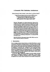
Seamless IP diversity based Generalized Mobility Architecture (SIGMA). Then we compare SIGMA’s performance with various MIPv6 enhancements. Similar in principle to other recent transport layer handover schemes [7], the basic idea of SIGMA is to exploit IP diversity to keep the old path alive during the process of setting up the new path to achieve a seamless handover. Recently, increasing number of mobile nodes are equipped with multiple interfaces to take advantage of overlay networks (such as WLAN and GPRS). The development of Software Radio technology also enables integrating multiple interface cards into one interface. Mobility supporting protocols should be able to utilize these new hardware advances to improve the performance. A new transport protocol proposed by IETF, called Stream Control Transmission Protocol (SCTP), has recently received much attention from the research community [8]. Multihoming is a built-in feature of SCTP, which is convenient to introduce IP diversity in mobile computing environments. Although we illustrate SIGMA using SCTP, it is important to note that SIGMA can be used with other protocols that support IP diversity. It can also cooperate with normal IPv4 or IPv6 infrastructure without the support of Mobile IP. B. Contributions of current research The contributions of our paper can be outlined as follows: • Propose and develop a seamless mobility architecture, SIGMA. Here “seamless” means low latency and low packet loss. • Compare the performance of SIGMA with various MIPv6 enhancements including FMIPv6, HMIPv6 and FHMIPv6. C. Paper structure The rest of this paper is structured as follows: Sec. II outlines the architecture of SIGMA. Then we compare the performance of SIGMA with MIPv6 enhancements by simulation. Simulation setup is described in Sec. III. The results of performance comparison are provided in Sec. IV. Finally, concluding remarks are presented in Sec. V. II. A RCHITECTURE OF SIGMA A typical mobile handover in SIGMA using SCTP as an illustration is shown in Fig. 1, where the Mobile Host (MH)
3249 0-7803-8938-7/05/$20.00 (C) 2005 IEEE
is multi-homed node connected through two wireless access networks. Correspondent node (CN) is a single-homed node sending traffic to MH, which corresponds to the services like file downloading or web browsing by mobile users. Correspondent Node
th Pa 2
Wireless Access Network2
Wireless Access Network1
Access Router 1
IP 1
IP 2
Access Router 2
Multi-homed Mobile Host
Fig. 1.
B. Timing diagram of SIGMA
An SCTP association with multi-homed mobile host.
A. Handover Process The handover process of SIGMA can be described by the following five steps using the SCTP protocol. STEP 1: Obtain new IP address Refer to Fig. 1 as an example, the handover preparation procedure begins when MH moves into the overlapping radio coverage area of two adjacent subnets. Once the MH receives the router advertisement from the new access router (AR2), it should begin to obtain a new IP address (IP2 in Fig. 1). This can be accomplished through several methods: DHCP, DHCPv6, or IPv6 stateless address auto-configuration (SAA) [9]. STEP 2: Add IP addresses into the association After the MH obtained the IP address IP2 by STEP 1, MH should notify CN about the availability of the new IP address through SCTP Address Dynamic Reconfiguration option [10]. This option defines two new chunk types (ASCONF and ASCONF-ACK) and several parameter types (Add IP Address, Delete IP address, and Set Primary Address etc.). STEP 3: Redirect data packets to new IP address When MH moves further into the coverage area of wireless access network2, CN can redirect data traffic to new IP address IP2 to increase the possibility that data can be delivered successfully to the MH. This task can be accomplished by sending an ASCONF from MH to CN, through which CN set its primary destination address to MH’s IP2. STEP 4: Update location manager (LM) SIGMA supports location management by employing a location manager which maintains a database recording the correspondence between MH’s identity and MH’s current primary IP address. MH can use any unique information as its identity such as home address like MIP, or domain name, or a public key defined in Public Key Infrastructure (PKI). We can observe an important difference between SIGMA and MIP: the location management and data traffic forwarding functions are coupled together in MIP, while in SIGMA they are decoupled
Fig. 2 summarizes the signalling sequences involved in SIGMA. The numbers before the events correspond to the step numbers in Sec. II-A. Here we assume IPv6 SAA is used by MH to get new IP address. It should be noted that before the old IP is deleted at CN, it can always receive data packets (not shown in the figure) in parallel with the exchange of signalling packets. Mobile Host
Ag en t
AR1
Adv ertis
AR2
Correspondent Node
Location Manager
discover new IP address
emen t
1. Compute the new IP Address by agent advertisement (IPv6 SAA)
2. Sen d
A sco nf
Ch un k
to no ti fy
new IP
2. Send ASCONF-ACK Chunk
Time
Pa th
1
One SCTP Association Core Router
to speedup handover and make the deployment more flexible. STEP 5: Delete or deactivate obsolete IP address When MH moves out of the coverage of wireless access network1, no new or retransmitted data should be directed to address IP1. In SIGMA, MH notifies CN that IP1 is out of service for data transmission by sending an ASCONF chunk to CN to delete IP1 from CN’s available destination IP list. A less aggressive way to prevent CN from sending data to IP1 is MH advertising a zero receiver window (corresponding to IP1) to CN. By deactivating, instead of deleting, the IP address, SIGMA can adapt more gracefully to MH’s zigzag movement patterns and reuse the previously obtained IP address (IP1) as long as the IP1’s lifetime is not expired. This will reduce the latency and signalling traffic caused by obtaining a new IP address.
3. Send ASCO NF Chu
4. Location Up
nk to SetPri mary
date ate ACK
4. Location Upd
3. Send AS
5. Delete or
CON F-A CK
deacti vate old
F- AC K Ch 5. Send ASCON
Fig. 2.
Chunk
Location update and CN update
IP unk (if delete)
Timing diagram of SIGMA
C. Location management SIGMA needs to setup a location manager which, unlike MIP, is not restricted to the same subnet as MH’s home network (in fact, SIGMA has no concept of home or foreign network). This will make the deployment of SIGMA much more flexible than MIP. Location management can be achieved as shown by the sequences in Fig. 3. If we use the domain name as MH’s identity, we can merge the location manager into a DNS server. The idea of using a DNS server to locate mobile users can be traced back to [11]. The advantage of this approach is its transparency to existing network applications that use domain name to IP address mapping. An Internet administrative domain can allocate one or more location servers for its registered
3250
CN
MH fo r i o n e r y o c at u l Q 2. rre nt to er cu s w er y n A u . 3 eQ th
4. S
B. Simulation parameters et up
&
Da ta
Internet
1. Location Update LM/DNS server
Pa ck
We have used the following parameters in our simulations: • A pair of FTP source and sink agents are attached to the CN and MH, respectively, to transfer bulk data from CN to MH. • Each AR has a radio coverage area of 40 meters in radius, and the overlapping region between two ARs is 10 meters. The advertisement period of the HA/AR1/AR2 is one second, but the advertisements from them are not synchronized. • To make a fair comparison, we have used standard SCTP protocol (without mobility related modifications) as the transport layer protocol for MIPv6 enhancements.
et s
Access Router
Mobile Host
Fig. 3.
Location management in SIGMA
mobile users. Compared to MIP’s requirement that each subnet must have a location management entity (HA), SIGMA can reduce system complexity and operating cost significantly by not having such a requirement. III. S IMULATION TOPOLOGY AND PARAMETERS
A. Handover latency
In this section, we describe the simulation topology and parameters that have been used to compare the performance of SIGMA and MIP. We have used ns-2 simulator that supports SCTP as the transport protocol, and incorporated FMIPv6, HMIPv6, FHMIPv6 implementations used by [12] and MIP route optimization used in [13]. We implemented SIGMA protocol in ns-2 to support the simulation comparison. A. Simulation Topology HA (MIPv6 ) / Location Manager (SIGMA)
CN
2
M Domain Address , 5-5 0m 1.0.0 s
, 2M
s 0m 5-5
Router1
2M, 50ms
Router2 2M
s
m
,2
Domain Address 2.0.0
2M
MH
Access Router1(AR1)
Fig. 4.
MH
,2
ms
MH
IV. R ESULTS In this section, we will show the comparison results between SIGMA and MIPv6 enhancements in terms of handover latency, throughput, packet loss rate, and network friendliness.
Domain Address 3.0.0
Access Router 2 (AR2)
Simulation topology.
The network topology used in our simulations for both MIPv6 and SIGMA is shown in Fig. 4. This topology has been used extensively in earlier MIP performance studies [3], [12]. In the figure, MIPv6 uses HA, while SIGMA uses it as Location Manager. Router2 in the topology will act as an MAP point in HMIPv6 and FHMIPv6, while act as only a normal router in FMIPv6 and SIGMA. The link characteristics, namely the bandwidth (Megabits/s) and propagation delay (milliseconds), are shown on the links.
We define the handover latency as the time interval between the last data segment received through the old path and the first data segment received through the new path from CN to MH. In this section, we will first show a packet trace of SIGMA to illustrate the seamless handover of SIGMA, then examine the impact of different parameters on the overall handover latency of SIGMA and MIPv6 enhancements. 1) Packet trace of SIGMA: Fig. 5(a) shows the packet trace observed at the CN during one typical handover for SIGMA with data being sent from CN to MH. The segment sequence numbers are shown as MOD 100. From Fig. 5(a) we can observe that data segments are sent to MH’s old IP address (2.0.1) until time 7.08 sec (point t1 ), then the new IP address (3.0.1) almost immediately (point t2 ), and all these packets are successfully delivered to MH. Therefore, SIGMA experienced a seamless handover because it could prepare the new path in parallel with data forwarding over the old path. This is the basic reason that explains why SIGMA can achieve a low handover latency, low packet loss rate and high throughput as will be shown in the following comparison with MIPv6 enhancements. 2) Impact of moving speed: We vary the moving speed of MH from 1.0m/s up to 15.0m/s. When MH moves faster, all MIPv6 enhancements and SIGMA will experience a higher handover latency due to shorter time to prepare for the handover (see Fig. 5(b)). However, the increase in speed has most significant effect on FMIPv6 since it relies on the assumption that detection of the new agent is well in advance of the actual handover. When the moving speed is higher, the assumption can break down more easily. Because HMIPv6 and SIGMA do not rely on this assumption, the effect of moving speed is smaller. But when moving speed is higher, there is higher possibility that packets are forwarded to the outdated path and get lost; therefore the time instant that MH can receive packets from the new path will be postponed, and the handover latency increases accordingly.
3251
Router1).
8
60
40 A A A AA A A AA A A A A A AA A A A A A A A
20
7
7.2
Data sent to 2.0.1 Data sent to 3.0.1 Ack received from 2.0.1 Ack received from 3.0.1
7.4
7 6
5
3
2 1
0 0
Time (s)
(a) Segment sequence of SIGMA during one handover. 1
7.5
12.5
10
Moving speed (m/s)
15
1
10
Handover latency (s)
Handover latency (s)
5
2.5
(b) Impact of moving speed
10
0
10
SIGMA FMIPv6 HMIPv6 FHMIPv6
−1
10
0
0
10
SIGMA FMIPv6 HMIPv6 FHMIPv6
−1
10
−2
−2
10
B. Packet loss rate and throughput
4
7.8
7.6
SIGMA FMIPv6 HMIPv6 FHMIPv6
50
100
150
HA−Router1 link delay (ms)
200
(c) Impact of HA-Router1 delay
Fig. 5.
10
0
50
100
150
CN−Router1 link delay (ms)
200
(d) Impact of CN-Router1 delay
SIGMA handover latency.
3) Impact of link delay between HA (LM) and Router1: Next, we vary the link delay between HA(LM) and Router1 from 5ms up to 200ms. The link delay between HA(LM) and Router1 decides the time that takes MH to update the location registration, and the effect of this link delay on the overall latency is shown in Fig. 5(c). Since SIGMA decouples the location management function from the critical handover process (see step 4 of Fig. 2), this link delay does not have impact on the latency of the SIGMA. This fact implies that we can put the location manager of SIGMA anywhere in the Internet without sacrificing the handover performance. For HMIPv6 and FHMIPv6, when MH moves between AR1 and AR2, it only needs to register with the MAP node (Router2). Thus the link delay between HA and Router1 does not have much impact on these two enhancements of MIPv6. However, each location update in FMIPv6 needs to go through this link between HA and Router1, which will increases the overall latency with an increase of the link delay. 4) Impact of link delay between CN and Router1: Next, we vary the link delay between CN and Router1 from 5ms up to 200ms. The link delay between CN and Router1 decides the time that takes MH to update the binding cache at CN (or CN’s protocol control block in OS kernel, in the case of SIGMA), the effect of this link delay on the overall latency is shown in Fig. 5(d). Our definition of handover latency does not require route optimization in versions of MIPv6 (binding update and return routability test) to finish. As long as the MH receives packets from the new path, either directly from CN or forwarded from HA, the handover is considered finished. Therefore, the link delay between CN and Router1 does not have much impact on the handover latency of MIPv6 enhancements. In contrast, SIGMA always requires updating CN before packets can be received from the new path. Therefore, the increase of this link delay will increase the handover latency (up to 109ms in the case of 200ms delay between CN and
We define the packet loss rate as the number of lost packets due to handover divided by the total number of packets sent by CN. The throughput is defined as the total useful bits that can be delivered to MH’s upper layer application divided by the simulation time, which gives us an estimate of average transmission speed that can be achieved. In this section, we will examine the impact of different parameters on the packet loss rate and throughput of SIGMA and MIPv6 enhancements. These parameters are the same ones as we have seen in Sec. IV-A. 1) Impact of moving speed: When MH moves faster, all versions of MIPv6 and SIGMA will experience a higher packet loss rate (Fig. 6(a)) and decreased throughput (Fig. 6(b)). This is because the possibility of packets being forwarded to the outdated path will increase with an increase in the speed. We can also notice that increase of speed has the most significant effect on FMIPv6 since it relies on the assumption that detection of the new agent is well in advance of the actual handover, which may not hold when MH moves fast. 5
7
0.035
SIGMA FMIPv6 HMIPv6 FHMIPv6
0.03
0.025
Throughput (bps)
t1t2
Packet loss rate(s)
Handover latency (s)
Segment sequence number
80
0.02
0.015
0.01
0.005 0 0
2.5
5
7.5
10
12.5
Moving speed (m/s)
(a) packet loss rate Fig. 6.
15
x 10
6
5
SIGMA FMIPv6 HMIPv6 FHMIPv6
4
3 2
1
0 0
2.5
5
7.5
10
12.5
Moving speed (m/s)
15
(b) throughput
Impact of moving speed on packet loss rate and throughput.
2) Impact of link delay between HA(LM) and Router1: As pointed out in Sec. IV-A.3, since SIGMA decouples the location management function from the critical handover process, this link delay does not have impact on the packet loss rate and throughput of SIGMA (Figs. 7(a) and 7(b)). For HMIPv6 and FHMIPv6, when MH moves between AR1 and AR2, it only needs to register with the MAP node (Router2), thus the link delay between HA and Router1 also does not have much impact on these two MIPv6 enhancements. However, each location update in FMIPv6 has to go through this link between HA and Router1, thus a higher delay in this link will result in packets forwarded by HA to have an increased possibility of being sent to an outdated location and being dropped. 3) Impact of link delay between CN and Router1: As shown in Sec. IV-A.4, the link delay between CN and Router1 does not have impact on the handover latency. As a result, the number of packets lost will remain the same with an increase of this link delay. However, a higher value of this link delay will increase RTT. Since the throughput of an SCTP association decreases as RTT increases, the total number of
3252
5
7
6.5
5.5
0.012
5
4.5
0.01
0.008
10
4
3.5
0.006
0.004
3
2.5
0.002
0 0
a new transport address, after a handover, which has different set of congestion control parameters from the old one.
SIGMA FMIPv6 HMIPv6 FHMIPv6
6
cwnd size (Byte x 1000)
Packet loss rate
0.014
Throughput (bps)
SIGMA FMIPv6 HMIPv6 FHMIPv6
0.016
x 10
50
100
150
HA−Router1 link delay (ms)
2 0
200
50
100
150
HA−Router1 link delay (ms)
(a) packet loss rate
200
(b) throughput
10
8
cwnd eovlution of 1.0.1 ( drop case) cwnd evolution of 1.0.1 (non-drop case) 6 4 2
Fig. 7.
Impact of HA-Router1 delay on packet loss rate and throughput.
10
packets sent to the MH will decrease. When we compute packet loss rate by dividing the number of packets lost divided by the total number of packets sent by CN, the resulting loss percentage will increase (Figs. 8(a) and 8(b)). For SIGMA, as this link delay increases, it has a negative effect on both packet loss (due to non-timely CN update) and throughput (longer RTT), so the packet loss rate increases relatively fast as compared to FHMIPv6 (Fig. 8(a)). 5
7
0.05
SIGMA FMIPv6 HMIPv6 FHMIPv6
0.04
0.035
Throughput (bps)
Packet loss rate
0.045
0.03
0.025
0.02
0.015
0.01
x 10
SIGMA FMIPv6 HMIPv6 FHMIPv6
6
5 4
50
100
150
CN−Router1 link delay (ms)
(a) packet loss rate Fig. 8.
200
8
cwnd eovlution of 2.0.1 cwnd evolution of 3.0.1
6 4 2
10.5
Time (s)
11
11.25
10
(a) MIP Fig. 9.
10.5
Time (s)
11
11.25
(b) SIGMA cwnd evolution during handover.
V. C ONCLUSIONS This paper presented SIGMA: a Seamless IP diversity based Generalized Mobility Architecture. After introducing the architecture of the protocol, we compared the performance of SIGMA with different Mobile IPv6 enhancements. Our results indicate that for typical network configuration and parameters, SIGMA has a lower handover latency, lower packet loss rate and higher throughput than MIPv6 enhancements. SIGMA has also been shown to be more network friendly than MIP.
3
Acknowledgment: We thank William Ivancic, Justin S. Jones, Song Lu for the numerous discussions that largely improved the quality of this paper.
2
1
0.005 0 0
cwnd size (Byte x 1000)
0.02
0.018
0 0
50
100
150
CN−Router1 link delay (ms)
200
R EFERENCES
(b) throughput
Impact of CN-Router1 delay on packet loss rate and throughput.
C. Network friendliness A network friendly mobility protocol requires that when an MH enters a new domain, CN should probe for the new domain’s network condition. In all MIP versions, CN’s transport protocol stack is not aware of the handover, it continues to use the old congestion window (cwnd). As shown in Fig. 9(a), CN’s cwnd remains constant after a handover around time 10.5 sec in the case where the handover latency is small enough that CN does not encounter a timeout resulting in drop of cwnd. This means that CN assumes the new network path to have the same capacity as the old one, which may cause network congestion if the new path does not have enough capacity. Although this network unfriendliness can sometimes help MIP achieve better throughput, it is not preferable from the perspective of network performance. Note that in MIP, the sender may be forced to slow start after a handover, due to packet losses during handover, as shown in Fig. 9(a) where the CN goes through a slow start starting at around 10.6 secs. In contrast to MIP, SIGMA exhibits better network friendliness. The sender always probes the new network path after a handover, regardless of segment drops. As shown in Fig. 9(b), the new network path is used starting from time 10.4 sec when the CN automatically begins a slow start sequence to avoid any possible congestion. This is because the CN switches over to
[1] D. Johnson, C.E. Perkins, and J. Arkko, “Mobility support in IPv6.” IETF RFC 3775, June 2004. [2] R. Koodli (editor), “Fast handovers for Mobile IPv6.” IETF DRAFT, draft-ietf-mipshop-fast-mipv6-03.txt, October 2004. [3] H. Soliman, C. Catelluccia, and K.E. Malki et al., “Hierarchical Mobile IPv6 mobility management (HMIPv6).” IETF DRAFT, draft-ietfmipshop-hmipv6-04.txt, December 2004. [4] R. Hsieh and A. Seneviratne, “A comparison of mechanisms for improving Mobile IP handoff latency for end-to-end TCP,” ACM MobiCom, San Diego, USA, pp. 29–41, September 2003. [5] D. A. Maltz and P. Bhagwat, “MSOCKS: An architecture for transport layer mobility,” INFOCOM, San Francisco, USA, pp. 1037–1045, March 1998. [6] A. C. Snoeren and H. Balakrishnan, “An end-to-end approach to host mobility,” ACM MobiCom, Boston, MA, pp. 155–166, August 2000. [7] S. J. Koh, M. J. Lee, M. L. Ma, and M. Tuexen, Mobile SCTP for Transport Layer Mobility. draft-sjkoh-sctp-mobility-03.txt, February 2004. [8] S. Fu and M. Atiquzzaman, “SCTP: State of the art in research, products, and technical challenges,” IEEE Communication Magazine, vol. 42, no. 4, pp. 64–76, April 2004. [9] S. Thomson and T. Narten, “IPv6 stateless address autoconfiguration.” IETF RFC 2462, December 1998. [10] R. Stewart, M. Ramalho, and Q. Xie et. al., “Stream control transmission protocol (SCTP) dynamic address reconfiguration.” IETF DRAFT, draftietf-tsvwg-addip-sctp-09.txt, June 2004. [11] B. Awerbuch and D. Peleg, “Concurrent online tracking of mobile users,” ACM SIGCOMM Symposium on Communications, Architectures and Protocols, pp. 221–233, September 1991. [12] Robert Hsieh, Zhe Guang Zhou, and Aruna Seneviratne, “S-MIP: A seamless handoff architecture for Mobile IP,” IEEE INFOCOM, San Francisco, CA, pp. 1774–1784, April 2003. [13] H. Chen and Lj. Trajkovic, “Route optimization in Mobile IP,” Workshop on Wireless Local Networks (WLN), Tampa, FL, pp. 847–848, November 2002.
3253