This article has been accepted for inclusion in a future issue of this journal. Content is final as presented, with the exception of pagination. IEEE TRANSACTIONS ON VERY LARGE SCALE INTEGRATION (VLSI) SYSTEMS
1
Area-Efficient Scalable MAP Processor Design for High-Throughput Multistandard Convolutional Turbo Decoding Chen-Hung Lin, Student Member, IEEE, Chun-Yu Chen, Student Member, IEEE, and An-Yeu Wu (Andy), Member, IEEE
Abstract—Most of advanced wireless standards, such as WiMAX and LTE, have adopted different convolutional turbo code (CTC) schemes with various block sizes and throughput rates. Thus, a reconfigurable and scalable hardware accelerator for multistandard CTC decoding is necessary. In this paper, we propose scalable maximum a posteriori algorithm (MAP) processor designs which can support both single-binary (SB) and double-binary (DB) CTC decoding, and handle arbitrary block sizes for high throughput CTC decoding. We first propose three combinations of parallel-window (PW) and hybrid-window (HW) MAP decoding. Moreover, the computational modules and storages of the dual-mode (SB/DB) MAP decoding are designed to achieve a high area utilization. To verify the proposed approaches, a 1.28 mm2 dual-mode 2PW-1HW MAP processor is implemented in 0.13 m CMOS process. The prototyping chip achieves a maximum throughput rate of 500 Mb/s at 125 MHz with an energy efficiency of 0.19 nJ/bit and an area efficiency of 3.13 bits/mm2 . For the multistandard systems, the expected throughput rates of the WiMAX and LTE CTC schemes is achieved by using five dual-mode 2PW-1HW MAP processors. Index Terms—Maximum a posteriori algorithm (MAP), multistandard platform, turbo codes.
I. INTRODUCTION ITH RAPID growth of multimedia services, the convolutional turbo code (CTC) has been widely adopted as one of forward error correcting (FEC) schemes of wireless standards to have a reliable transmission over noisy channels. Single-binary (SB) CTC, proposed in 1993 [1], has been the well-known FEC code that can achieve high data rates and coding gains close to the Shannon limit. The SB CTC code has been adopted in the FEC schemes of wideband code division multiple access (WCDMA) [2], high-speed downlink packet access (HSDPA) [2], and long term evolution (LTE) [2]. In 1999, non-binary CTC [3] was introduced to achieve superior performance than the SB CTC. In recent years, double-binary (DB) CTC has been adopted in advanced wireless communication standards, such as worldwide interoperability for microwave
W
Manuscript received February 13, 2009; revised June 13, 2009. This work was supported in part by Industrial Technology Research Institute, R.O.C., under the WiMAX FEC Project 8362B51310, and by National Science Council, R.O.C., under Grants NSC 95-2219-E-002-020 and 95-2220-E-002-024. The material in this paper was presented in part at the IEEE SiPS 2008, DC, USA. The authors are with the Graduate Institute of Electronics Engineering and Department of Electrical Engineering, National Taiwan University, Taipei 10617, Taiwan (e-mail:
[email protected]). Digital Object Identifier 10.1109/TVLSI.2009.2032553
TABLE I SPECIFICATIONS OF THE PREVALENT WIRELESS WIDE AREA NETWORKS
access (WiMAX) [4]. Table I lists the detailed specifications and the CTC schemes of the prevalent wireless standards for wide area networks (WANs). Some CTC decoders have been implemented as application-specific integrated circuits (ASICs), such as the HSDPA CTC decoder [5] and WiMAX CTC decoder [6]. Recently, high-end portable/mobile devices become prevalent in wireless markets. There are large growing emergence and demands for an inexpensive solution to access the ubiquitous wireless services. Meanwhile, these wireless standards, such as 3GPP and WiMAX standards, adopted CTC schemes with different coding parameters and different throughput rates [8], [9]. To deal with the accelerated evolution of these standards, the multistandard platforms which can seamlessly work across the multiple standards were proposed in [7]. Hence, a CTC decoding accelerator which works in the multistandard platforms is desired to achieve the smooth migration for the multiple wireless applications. In this paper, we propose area-efficient scalable processor designs of the maximum a posteriori algorithm (MAP) [10] for multistandard CTC schemes. In Figs. 1(a)–(c), the proposed MAP processor can be the deterministic or reconfigurable FEC components. In Fig. 1(d), several proposed MAP processors can be used in multiple processors for system-on-chip (MPSoC) technology for a multistandard platform. The proposed scalable MAP processor design for high-throughput multistandard CTC schemes has two features stated as follows. • Combined parallel-window (PW) and hybrid-window (HW) MAP decoding: The parallel processing of the MAP decoding has been described in [11]–[17]. To support high-throughput decoding for any CTC block sizes, area-efficient combinations of PW [12] and HW [14] MAP decoding are proposed. We present three combinations (1PW-1HW, 2PW-1HW and modified 2PW-1HW) of
1063-8210/$26.00 © 2009 IEEE Authorized licensed use limited to: National Taiwan University. Downloaded on July 12,2010 at 08:28:40 UTC from IEEE Xplore. Restrictions apply.
This article has been accepted for inclusion in a future issue of this journal. Content is final as presented, with the exception of pagination. 2
IEEE TRANSACTIONS ON VERY LARGE SCALE INTEGRATION (VLSI) SYSTEMS
Fig. 1. Proposed area-efficient scalable MAP processor and its applications: the (a) 3GPP CTC decoder; (b) WiMAX CTC decoder; (c) 3GPP/WiMAX CTC decoder; and (d) programmable multistandard platform in a MPSoC platform.
MAP decoding to perform the alternative PW and HW MAP decoding. • Dual-mode single-binary/double-binary (SB/DB) MAP decoding: The dual-mode MAP decoding for multistandard CTC schemes has been introduced in [18], [19]. The radix-4 SB and radix-4 DB MAP is reformulated to achieve high hardware usages and fully-shared storages of the dualmode MAP decoding. In this paper, the shared module design of dual-mode MAP is described in detail. Based on silicon area evaluations, the hardware overhead of dualmode MAP is less than 10% compared with the individual radix-4 SB MAP or individual radix-4 DB MAP. Furthermore, a prototyping chip of the proposed dual-mode 2PW-1HW MAP processor is implemented in a core size of 1.28 mm with a 0.13 m CMOS process. This processor achieves a maximum throughput rate of 500 Mb/s at 125 MHz operating frequency, an energy efficiency of 0.19 nJ/bit, and an area efficiency of 3.13 bits/mm . The advanced wireless applications of Fixed WiMAX and LTE standards can be achieved by using five prototyping dual-mode 2PW-1HW MAP processors. The rest of this paper is organized as follows. In Section II, we review fundamentals of the MAP. Three combinations of areaefficient scalable MAP decoding are proposed in Section III. The throughput analyses and design guidance for area-efficient CTC decoding are described in Section IV. The reconfigurable VLSI design of dual-mode (SB/DB) MAP decoding is described in Section V. Section VI presents the experimental results and prototyping MAP processor for multistandard CTC decoding. Finally, Section VII concludes this paper. II. REVIEWS OF MAP DECODING Background reviews of the SB and DB MAP are demonstrated in this section. Then, window-based decoding is briefly demonstrated. A. Decoding Algorithms For CTC decoding, powerful soft-input soft-output (SISO) algorithms are the MAP and its derivatives, such as the log-MAP (L-MAP) [20], Max-log-MAP (ML-MAP) [20], combinations of the L-MAP and ML-MAP [21], and enhanced Max-log-MAP
Fig. 2. PW MAP decoding: the (a) Basic parallel window and (b) overall timing chart.
(EML-MAP) [22]. The differences between the L-MAP and (E)ML-MAP are that a priori log-likelihood-ratio (LLR) muloperations are replaced by tiplies the channel value and in the L-MAP. The [20] is defined as
(1) A lookup table (LUT) can implement the corrective term . The difference between the EML-MAP and ML-MAP is that the extrinsic information in the EML-MAP multiplies a . The EML-MAP achieves better scaling factor coding gain than the ML-MAP. Without specifying which algorithm is used, we use the name MAP for a short abbreviation of the L-MAP and (E)ML-MAP in the following sections. , forIn general, the MAP is composed of branch metrics ward recursion state metrics , backward recursion state met, a priori LLR , a posteriori LLR , and rics . For the dual-mode MAP decoding, extrinsic information the radix-4 SB MAP decoding and radix-4 DB MAP decoding are employed because of their computational similarity. The reviews of the radix-4 SB and radix-4 DB ML-MAP decoding are introduced as follows. 1) Radix-4 Single-Binary (SB) MAP Decoding: The SB CTC encodes one binary bit at time . For decoding two binary bits at a time, the radix-4 SB ML-MAP algorithm has been derived in [15] by a look-ahead technique. The arithmetic operations of the radix-4 SB ML-MAP are described as shown in (2a)–(2e) at the next bottom of the page, where
Authorized licensed use limited to: National Taiwan University. Downloaded on July 12,2010 at 08:28:40 UTC from IEEE Xplore. Restrictions apply.
This article has been accepted for inclusion in a future issue of this journal. Content is final as presented, with the exception of pagination. LIN et al.: AREA-EFFICIENT SCALABLE MAP PROCESSOR DESIGN
,
transmitted codewords
,
soft received values;
3
for BPSK;
,
,
soft received values; number of ach parity bit; .
state index; number of each parity bit. The sign bit of the a posteriori LLR value decides whether or . 2) Radix-4 Double-Binary (DB) MAP Decoding: The DB at time . For CTC encodes two binary bits decoding the DB CTC schemes, the arithmetic operations of the radix-4 DB ML-MAP [23] are described as shown in (3a)–(3f) at the bottom of the page, where intrinsic information; ,
,
transmitted codewords
;
are based on (4), shown at the bottom of the Decisions , , , and next page. Note that the values of the are always zero. B. Window-Based MAP Decoding The well-known windowing technique [24] was proposed to facilitate memory costs of CTC decoders. Some VLSI architectures of the sliding window (SW) MAP decoding can be referred to in [14], [25]–[30]. The SW MAP decoding deals with any CTC block size but has an intrinsic low throughput rate. Thus, several works in [11]–[17] have been introduced to achieve high throughputs by using parallel processing techniques within a
(2a) (2b) (2c)
(2d)
(2e)
(3a) (3b) (3c)
(3d) (3e)
(3f)
Authorized licensed use limited to: National Taiwan University. Downloaded on July 12,2010 at 08:28:40 UTC from IEEE Xplore. Restrictions apply.
This article has been accepted for inclusion in a future issue of this journal. Content is final as presented, with the exception of pagination. 4
IEEE TRANSACTIONS ON VERY LARGE SCALE INTEGRATION (VLSI) SYSTEMS
Fig. 3. HW MAP decoding: the (a) basic sliding window; (b) basic parallel window; and (c) overall timing chart.
CTC block. Two fundamental types of parallel processing techniques are stated as follows. 1) Parallel Window (PW) MAP Decoding: The fully parallel window-based MAP decoding, called PW MAP decoding in this paper, was introduced in [12] and optimized in [14] (under the rubric of hybrid tiling). Fig. 2(b) shows the timing chart of the PW MAP decoding. The timing chart [25] is a widely-used tool to analyze the behavior of MAP decoding. In this timing chart, the vertical axis denotes the decoding symbol axis and the horizontal axis denotes the decoding time axis. The acquisition depth defined by the windowing technique is denoted by , and [24], where is the constraint length of a recursive systematic convolutional (RSC) encoder. Note that the warm-up window length in Fig. 2 would be longer for punctured CTC schemes. The timing chart of MAP decoding is mainly composed of the branch metric acquisition, forward state metrics recursion, backward state metrics recursion, and a posteriori LLR acquisition. In Fig. 2(b), the PW MAP decoding is composed of several basic parallel windows [see Fig. 2(a)]. The number of basic parallel window extended in symbol axis (vertical axis) is denoted by . One basic parallel window represents one PW MAP processor to perform the PW MAP decoding. The decoding latency of the PW MAP processor is . Due to the fully parallel processing, the PW MAP decoding is designed to decode a CTC subbanks of the input, output and internal (exblock with trinsic) buffers. When becomes spectacularly large to decode a large CTC block, the area cost and power consumption of PW MAP processors is intolerably large. Thus, the PW MAP decoding is not suitable for decoding a large CTC block.
2) Hybrid Window (HW) MAP Decoding: To deal with large CTC blocks, the partial parallel window-based MAP decoding, called HW MAP decoding in this paper, was introduced in [13] and optimized in [14] (under the rubric of lateral tiling). In contrast to the PW MAP decoding, the HW MAP decoding has the feature of parallel processing in sequential time. Fig. 3(c) shows the timing chart of the HW MAP decoding for large CTC blocks. The timing chart is composed of basic parallel windows [see Fig. 3(b)] and each basic parallel window is composed of basic sliding windows [see Fig. 3(a)]. The basic parallel window is extended in symbol axis (vertical axis) in parallel, and the basic sliding window is sequentially extended in time axis (horizontal axis). One basic parallel window represents one HW MAP processor. The decoding latency of HW MAP processor is . III. PROPOSED AREA-EFFICIENT SCALABLE MAP DECODING The aforementioned parallel processing techniques are the individual PW MAP decoding and individual HW MAP decoding. In this paper, we intend to propose area-efficient scalable MAP processors which can alternatively operate on both the PW and HW MAP decoding. In this section, three combinations of the PW and HW MAP decoding are proposed. A. 1PW-1HW MAP Decoding A straightforward way to achieve the alternative PW and HW MAP decoding is to assemble one scalable MAP processor of the PW MAP decoding and one scalable MAP processor of the HW MAP decoding into a MAP processor. Hence, the 1PW-1HW MAP decoding is proposed to alternatively
(4)
Authorized licensed use limited to: National Taiwan University. Downloaded on July 12,2010 at 08:28:40 UTC from IEEE Xplore. Restrictions apply.
This article has been accepted for inclusion in a future issue of this journal. Content is final as presented, with the exception of pagination. LIN et al.: AREA-EFFICIENT SCALABLE MAP PROCESSOR DESIGN
5
Fig. 4. Architecture of the 1PW-1HW MAP processor.
perform the PW and HW MAP decoding with shared computational units and storages. Fig. 4 shows the architecture of the 1PW-1HW MAP processor in PW and HW modes which perform one parallel window of the PW MAP decoding shown in Fig. 2(b) and one parallel window of the HW MAP decoding shown in Fig. 3(c). The decoding latency of the 1PW-1HW in PW mode and in HW mode. MAP decoding achieves It keeps the same throughput of the HW MAP decoding for large CTC blocks and speeds up the throughput for small CTC blocks. The architecture of the 1PW-1HW MAP processor shown in Fig. 4 is composed of two branch metrics units (BMUs), eight branch metric caches (BMCs), one backward , one forward recursion recursion processing element , one dummy backward processing processing element ), two state metric caches (SMCs), and two element a posteriori LLR modules (LAPOs). Because there is a cross and within an window, composed of the two BMCs composed of two single-port (SP) random-access are required. Two memories (RAMs) with a depth of store SMCs composed of two SP RAMs with depth of and until is calculated by two LAPOs in the forward and backward directions. , one , two In Fig. 4, two BMUs, two BMCs, one SMCs, and two LAPOs are active in PW mode. In contrast to only one branch metrics acquisition used in the basic parallel window of HW MAP decoding [see Fig. 3(b)], two branch metrics acquisitions are used in the basic parallel window of PW MAP decoding [see Fig. 2(a)]. Thus, two BMUs work in parallel in PW mode to concurrently generate the forward and backward branch metrics. Compared to the HW MAP processor which only performs the individual HW MAP decoding, the 1PW-1HW MAP processor is able to perform the PW MAP decoding because of an additional cost of BMU. Note that one scalable MAP processor of the PW MAP decoding is shown in Fig. 4 when the unique paths and blocks in HW mode are removed. In HW mode, the 1PW-1HW MAP processor is fully active. provides the reliable warm-up to the . The The branch metrics and store them into BMUs have to generate decoding time. Thus, each BMU the eight BMCs in every generates branch metrics and stores them into four BMCs in
Fig. 5. Architecture of the 2PW-1HW MAP processor.
decoding time. Note that one scalable MAP processor every of the HW MAP decoding is shown in Fig. 4 when one BMU is removed and the two input paths of BMC are connected. B. 2PW-1HW MAP Decoding To perform critical decoding for small CTC blocks, the MAP processor needs to provide higher decoding ability in PW mode. Some computational units and storages are added into the 1PW-1HW MAP processor, and the new MAP processor can provide higher decoding ability in PW mode. The 2PW-1HW MAP decoding is proposed to perform the alternative MAP decoding for critical decoding in PW mode. Fig. 5 shows the architecture of 2PW-1HW MAP processor. The 2PW-1HW MAP processor in HW mode still performs one parallel window of the HW MAP decoding shown in Fig. 3(c). In PW mode, however, the 2PW-1HW MAP processor performs two parallel windows of PW MAP decodings shown in Fig. 2(b). The decoding latency of the 2PW-1HW MAP decoding achieves in PW mode and in HW mode. Compared with the 1PW-1HW MAP processor, the 2PW-1HW MAP processor , two SMCs, and two LAPOs. Each adds two BMUs, one branch metrics and stores them into two BMU generates decoding time. In PW mode, only four BMCs in every BMCs (dashed blocks in Fig. 5) are idle. It results in an efficient computational hardware usage for the 2PW-1HW MAP processor in PW mode. C. Modified 2PW-1HW MAP Decoding The 2PW-1HW MAP decoding was especially proposed to perform the critical decoding for small CTC blocks in PW mode. To further achieve a higher throughput rate in HW mode, the modified 2PW-1HW (M2PW-1HW) MAP decoding is proposed based on an observation on the architecture of 2PW-1HW MAP processor. In Fig. 5, two BMUs can be rebranch metrics calculation in every alized to generate decoding time. Fig. 6(a) and (b) show the modified basic sliding
Authorized licensed use limited to: National Taiwan University. Downloaded on July 12,2010 at 08:28:40 UTC from IEEE Xplore. Restrictions apply.
This article has been accepted for inclusion in a future issue of this journal. Content is final as presented, with the exception of pagination. 6
IEEE TRANSACTIONS ON VERY LARGE SCALE INTEGRATION (VLSI) SYSTEMS
Fig. 6. Modified 2PW-1HW MAP decoding in HW mode: the (a) basic sliding window; (b) basic parallel window; and (c) overall timing chart.
window and parallel window, respectively. The timing chart of the M2PW-1HW MAP decoding in HW mode is shown in Fig. 6(c). The decoding latency in HW mode is reduced from to . The M2PW-1HW MAP decoding still performs two parallel windows of PW MAP decoding [see Fig. 2(b)], in PW mode. However, and achieves the decoding latency the design overhead for using the M2PW-1HW MAP decoding is that the input, output, and internal (extrinsic) buffers of CTC decoders must support two reads in a cycle to generate the branch metrics in time. Thus, the support of two reads in a memory access increases the read ports or subbanks of the buffers of CTC decoders. IV. THROUGHPUT ANALYSES FOR AREA-EFFICIENT CTC DECODING In this section, a general throughput rate form of the windowbased CTC decoding is described. Then, throughput analyses of the proposed MAP decoding are demonstrated. A. General Throughput Rate Form for CTC Decoding For a systematic analysis of the aforementioned MAP decoding, the achievable throughput rate is applied to decode a CTC block and given by Throughput Rate where the notations are defined as decoded hard bit per clock cycle;
(5)
decoded CTC block size
;
maximal number of PW MAP processing; Ä pipeline stages of MAP processor; operating frequency of MAP processor; basic window size
;
decoding latency of MAP decoding; number of parallel windows
;
number of sliding windows; number of CTC decoding iterations. Note that equals 1 for radix-2 MAP decoding and 2 for radix-4 MAP decoding. Pipeline stages of a MAP processor are generally small and ignored in the following systematic throughput analyses. Table II lists a design summary of the aforementioned MAP decoding for the following systematic throughput analyses. The denotes the smallest integer not less than . In function general, the SW MAP decoding only takes one SW MAP processor for CTC decoding so equals 1. When a single CTC block size is smaller than , this block is defined as a small CTC block and decoded in PW mode. Otherwise, the CTC block is defined as a large CTC block and decoded in HW mode. For the PW MAP decoding and the proposed MAP decoding in PW mode, is fixed to 1. For the HW MAP decoding and the proposed MAP decoding in HW mode, the number of parallel decoding cannot larger than the maximal number of PW . In addition, of the MAP decoding so is fixed to
information bits in a CTC block; Authorized licensed use limited to: National Taiwan University. Downloaded on July 12,2010 at 08:28:40 UTC from IEEE Xplore. Restrictions apply.
This article has been accepted for inclusion in a future issue of this journal. Content is final as presented, with the exception of pagination. LIN et al.: AREA-EFFICIENT SCALABLE MAP PROCESSOR DESIGN
7
TABLE II SUMMARY OF THE DISTINCT MAP DECODING FOR SYSTEMATIC ANALYSES
Fig. 8. Throughput results of the 1PW-1HW MAP decoding analyzed on I
5 and f = 125 MHz for small block sizes.
Fig. 7. Throughput results of the HW, 1PW-1HW, 2PW-1HW, and M2PW-1HW MAP decoding analyzed on I and f 125 MHz.
=5
=
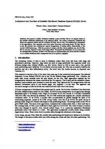
(M)2PW-1HW MAP decoding in HW mode is because the (M)2PW-1HW MAP decoding can perform two windows of PW decoding and one window of HW decoding. Note that the SW MAP decoding can be regarded as a special case of the HW MAP decoding or proposed MAP decoding in HW mode when only one MAP processor is used. B. Throughput Analyses of the Proposed MAP Processors In this paper, the specifications of Fixed WiMAX and LTE are used to be the norm of throughput analyses. We specify that the expected throughput rate is 100 Mb/s in order to meet the specifications of Fixed WiMAX and LTE. Besides, the Fixed WiMAX clearly defined the block sizes larger than 240 as large CTC blocks for the optional hybrid automatic repeat request (HARQ) transmissions, and other block sizes as small CTC blocks for the general data transmissions. Thus, two expected throughput rates are obtained when the radix-4 SB/DB MAP is adopted. One is 100 Mb/s at , and decoding . Both Fixed WiMAX and the other is 100 Mb/s at LTE adopted the CTC scheme composed of the parallel concatenated 8-state RSC encoder where is 4. In this paper, we which is indicated by . let Fig. 7 shows the throughput results of the aforementioned 125 MHz and . The iteraMAP decoding based on is referred to in [8] and [31]. Fig. 8 shows the tion number detailed throughput results of the 1PW-HW MAP decodings in PW mode with varying from 9 to 11. The throughput analyses
=
of the SW decoding and PW MAP decoding are ignored because of the intrinsic low throughputs of the SW MAP decoding and the intolerant hardware costs of the numerous PW MAP processors. Three observations based on Fig. 7 can be made as follows. • The throughput rates are dramatically degraded when the MAP decoding enters HW mode from PW mode. • For the conventional HW MAP decoding with the de, 10 HW MAP processors in PW coding latency of . mode cannot meet the expected throughput at However, the 10 1PW-1HW MAP processors in PW mode , as properly meet the expected throughput at shown in Fig. 8. It implies that 5 (M)2PW-1HW MAP processors can meet the same expected throughput at . • Though all of the proposed MAP decoding can meet the in HW mode, the expected throughput at throughput rate of 10 1PW-1HW MAP processors is much higher than others and approaching to 180 Mb/s. On the other hand, the throughput rate of 5 2PW-1HW MAP processors in HW mode is near the expected throughput . It implies that too many 1PW-1HW rate at MAP processors are used to meet the expected throughput rate in PW mode and result in the overdesigned MAP processors in HW mode. We define the area cost of two 1PW-1HW MAP processors to be times area cost of one (M)2PW-1HW MAP processor. We assume the 2PW-1HW and M2PW-1HW MAP processors to have the same hardware cost because of their same architecture shown in Fig. 5. If is less than 2, the (M)2PW-1HW MAP processors have efficient area to achieve the expected throughput and at . Based on the hardware evalrates at uations in Section VI-A, is less than 1.5 under the synthesis results of the MAP processors (see Table V). Thus, to meet the expected throughput rates of Fixed WiMAX and LTE standards, the 5 (M)2PW-1HW MAP processors have lower area costs than 10 1PW-1HW MAP processors. Rough guidance of choosing the proposed MAP processors based on the aforementioned results is listed as follows.
Authorized licensed use limited to: National Taiwan University. Downloaded on July 12,2010 at 08:28:40 UTC from IEEE Xplore. Restrictions apply.
This article has been accepted for inclusion in a future issue of this journal. Content is final as presented, with the exception of pagination. 8
IEEE TRANSACTIONS ON VERY LARGE SCALE INTEGRATION (VLSI) SYSTEMS
Fig. 9. Proposed dual-mode (SB/DB) MAP decoding path.
1) Determine and based on high-level simulations, and based on static timing analyses. 2) Determine MaxP in order to meet the throughput rate in PW mode. 3) Determine the type of the proposed MAP processors based on Table II and a sequential order: from the 2PW-1HW MAP decoding to the M2PW-1HW MAP decoding, and then to the 1PW-1HW MAP decoding. Once the expected throughput rate in HW mode is met during determining the type of the proposed MAP processors, the area-efficient MAP processors are achieved.
Fig. 10. Block diagram of the branch metrics decomposition.
data of branch metrics of the radix-4 SB MAP decoding are defined as
V. VLSI DESIGN OF DUAL-MODE MAP DECODING To support the multistandard CTC schemes, we intend to design dual-mode computational modules of the alternative SB and DB MAP decoding with high hardware usages and fully-shared storages. For the dual-mode MAP decoding, it is straightforward to implement the radix-4 SB and DB MAP decoding because of their similar radix-4 trellis structure. The dual-mode branch metrics decomposition is proposed to substitute the conventional BMU for the first and second stages of the BMU (BMU-S1 and BMU-S2) and to reduce the size of the BMC. The trellis structures of the radix-4 SB/DB MAP decoding, and the dual-mode LAPO and extrinsic information module (LEX) are also described in this section. The natural recursion processing element (NRP) composed of radix-2 2 add-compare-select units (ACSUs), and traceback recursion processing element (TRP) composed of radix-2 2 traceback units [32] are adopted to reduce the size of SMC. Fig. 9 shows the proposed dual-mode MAP decoding path composed of the BMU-S1, BMU-S2, BMC, NRP, SMC, TRP, LAPO, and LEX. or . Note that the NRP can be the A. Branch Metrics Decomposition for Radix-4 SB/DB MAP Decoding For the both radix-4 SB and DB MAP decoding, the BMU and BMC designs become critical because 16 branch metrics are generated and stored. The decomposed branch metrics of the radix-2 SB MAP decoding was proposed in [30] to reduce the storages of four branch metrics. The datapath of the branch metrics decomposition is shown in Fig. 10. Partial data of the branch metrics generated by the BMU-S1 are stored into the BMC which is smaller than the conventional one. When the real branch metrics are required, they are calculated by the BMU-S2 with the stored partial data. In addition, the stored partial data are also used to generate the extrinsic information. To reduce the BMC size of the radix-4 SB MAP decoding, where the 16 branch metrics in (2a) are indicated as , and the suffix “2” denotes the Boolean numerical notation. The partial
(6)
, , , , , and inThe BMC only stores stead of the 16 branch metrics. Then, the 16 branch metrics can be computed by (7) where
,
,
, and . The denotes the largest integer not bigger than . function In addition, the extrinsic information in (2e) can be computed by (8) To reduce the BMC size of the DB MAP decoding, the 16 where branch metrics in (3a) are indicted as . The partial data of branch metrics of the DB MAP decoding are defined as
(9)
, , , , , and The BMC only stores instead of the 16 branch metrics. Then, the 16 branch metrics can be computed by
Authorized licensed use limited to: National Taiwan University. Downloaded on July 12,2010 at 08:28:40 UTC from IEEE Xplore. Restrictions apply.
(10)
This article has been accepted for inclusion in a future issue of this journal. Content is final as presented, with the exception of pagination. LIN et al.: AREA-EFFICIENT SCALABLE MAP PROCESSOR DESIGN
9
Fig. 12. Trellis diagram of the (a) Radix-4 SB and (b) Radix-4 DB MAP decoding.
by , and by . Fig. 11 show the corresponding logic blocks of the BMU-S1 for the dual-mode MAP decoding. The signal “Mode” is used to configure the dual-mode BMU-S1. When “Mode” is active low, the dual-mode BMU-S1 operates in SB mode. Based on the observation of the second stage of branch metrics calculation in (7) and (10), the adders of the corresponding dual-mode BMU-S2 are totally shared when and . To generate the radix-4 SB extrinsic information in (8), two subtractions, two additions, and two shift operations are required. To generate the radix-4 DB extrinsic information in (11), six subtractions are required. Thus, the dual-mode LEX can be composed of four subtracters and two binary adder-subtracters with the shift operations. Fig. 11. Dual-mode first stage of the BMU (BMU-S1) of the branch metrics decomposition for SB/DB MAP decoding: active logic blocks (a) in SB mode and (b) in DB mode.
where
,
,
, and . In addition, the extrinsic information in (3e) can be computed by
(11)
The aforementioned branch metrics decompositions require and . a fully-shared BMC when Based on the observation of the first stage of branch metrics calculation in (6) and (9), the computational hardware is equivby , alent when we replace by , by , by , by , by ,
B. Trellis Structure of Radix-4 SB/DB MAP Decoding Because of the distinct trellis structures of the radix-4 SB and radix-4 DB MAP decoding, the state connections of the trellis structures are different to each other. In Fig. 12, the radix-4 trellis structure has two same radix-4 butterflies. These two trellis structures (dashed blocks in Fig. 12) are the same if we regard the state 2 of SB trellis as the state 7 of DB trellis, the state 3 of SB trellis as the state 6 of DB trellis, the state 6 of SB trellis as the state 3 of DB trellis, and the state 7 of SB MAP as the state 2 of DB trellis. Based on this observation, there is no hardware overhead for the state connections because only the state indices are changed. However, multiplexers of choosing the branch metrics are implemented into the NRP and TRP because of the different branch metrics of the SB and DB MAP decoding. C. Dual-Mode LAPO for Radix-4 SB/DB MAP Decoding To achieve a high hardware usage of the dual-mode LAPO, the a-posteriori LLR in (2d) and (3d) are rewritten. By rewriting operations in (2d), is defined as
Authorized licensed use limited to: National Taiwan University. Downloaded on July 12,2010 at 08:28:40 UTC from IEEE Xplore. Restrictions apply.
This article has been accepted for inclusion in a future issue of this journal. Content is final as presented, with the exception of pagination. 10
IEEE TRANSACTIONS ON VERY LARGE SCALE INTEGRATION (VLSI) SYSTEMS
Fig. 13. Dual-mode LAPO for SB/DB MAP decoding.
where and
(12) for the radix-4 SB MAP decoding. Then, in (2d) are computed by
(13) By rewriting
operations in (3d),
is defined as
(14) Fig. 14. SB/DB MAP LLR calculator of the dual-mode LAPO: active logic blocks (a) in SB mode and (b) in DB mode.
for the radix-4 SB MAP decoding. Then, where in (3d) is computed by
TABLE III EVALUATION SPECIFICATION OF MAP DECODING
(15)
operations Based on the observation in (12)–(15), the and are the same. Therefore, the computational of hardware of the dual-mode LAPO can be shared. Fig. 13 shows the block diagram of the dual-mode LAPO. The module is composed of 3-level binary-tree-structured compareis the output of the shared select units (CSUs). The path operators of and . The LLR calculator performs three subtractions in (15), and two subtractions and operations in (13). Note that a operation is four implemented by a CSU. Thus, the subtracter in a CSU can be the subtraction of . The shared hardware design of the dual-mode LLR calculator is shown in Fig. 14. The signal “Mode” is used to configure the dual-mode LLR calculator. When “Mode” is active low, the dual-mode LLR calculator is in SB mode.
VI. EXPERIMENTAL RESULTS Fast and accurate hardware evaluations and power estimations are obtained by using Verilog HDL codes synthesized with the standard cell library of TSMC 0.13- m CMOS process. The practical evaluations of the proposed approaches are under the WiMAX and 3GPP CTC schemes shown in Table I. Table III lists evaluation parameters under the specification of WiMAX and 3GPP CTC schemes.
Authorized licensed use limited to: National Taiwan University. Downloaded on July 12,2010 at 08:28:40 UTC from IEEE Xplore. Restrictions apply.
This article has been accepted for inclusion in a future issue of this journal. Content is final as presented, with the exception of pagination. LIN et al.: AREA-EFFICIENT SCALABLE MAP PROCESSOR DESIGN
TABLE IV SILICON AREA OF THE KEY MODULES OF THE INDIVIDUAL RADIX-4 SB, INDIVIDUAL RADIX-4 DB, AND DUAL-MODE MAP DECODING
11
TABLE V AREA COMPARISONS OF THE INDIVIDUAL RADIX-4 SB, INDIVIDUAL RADIX-4 DB, DUAL-MODE 1PW-1HW, AND 2PW-1HW MAP PROCESSORS
storages, the BMC and SMC of the dual-mode MAP decoding are designed with the same size of storages. Table IV reveals that the modules of the radix-4 SB MAP decoding have the similar silicon area of the radix-4 DB MAP decoding except the small-area modules, i.e., the BMU and LEX. For the area-dominant combinational modules, i.e., the NRP and LAPO, the hardware overhead of the dual-mode NRP and LAPO is less than 16% compared with the individual radix-4 DB NRP and LAPO. Note that the hardware costs of the dual-mode NRP and TRP are increased because several multiplexers are implemented to choose the distinct branch metrics of the alternative SB and DB MAP decoding. Based on the area results shown in Table IV, Fig. 15 shows the area comparison of the active modules of the 1PW-1HW and 2PW-1HW MAP decoding in PW mode and HW mode. Note that the computational hardware costs of 2PW-1HW MAP and M2PW-1HW MAP processors are the same because of the same architecture shown in Fig. 5. The area utilization (AU) defined as Area of active modules Area of total modules
Fig. 15. Silicon area comparisons of all and active modules of the (a) 1PW-1HW MAP processor and (b) 2PW-1HW MAP processor.
A. Evaluations of Silicon Area The area results of individual radix-4 SB, individual radix-4 DB, and dual-mode MAP processors are synthesized at 100 MHz operating frequency by Synopsis Design Vision. Table IV shows the silicon comparison of key modules of the MAP decoding (see Fig. 9). Because of the requirement of fully-shared
(16)
is used to compare the area usage of the proposed MAP processors in PW and HW modes. In Fig. 15, though the 1PW-1HW MAP processor achieves 100% AU in HW mode, it only achieves around 60% AU in PW mode. However, the 2PW-1HW MAP processor achieves about 85% AU in PW mode and about 71% AU in HW mode. Thus, the 1PW-1HW MAP processor achieves a high area usage for decoding CTC blocks for large CTC blocks. The 2PW-1HW MAP processor achieves a high area usage for decoding small CTC blocks, which is suitable for WiMAX standards. Table V shows the overall silicon results of the individual radix-4 SB, individual radix-4 DB, and dual-mode MAP processors, including the key computational modules, the pipeline registers, and the processor controller. The synthesized results are still reported at 100 MHz operating frequency. The dualmode MAP processor achieves around 10% hardware overhead of the single-mode MAP processor, which is either the individual radix-4 SB or individual radix-4 DB MAP processors. Furthermore, the area ratio defined in Section IV-B is less than two so the 2PW-1HW MAP processor achieves the area-efficient feature described in Section IV. Table VI also shows that the dual-mode MAP processors achieve around 45% area reduction compared with the individual radix-4 SB plus DB MAP processors. Thus, the proposed
Authorized licensed use limited to: National Taiwan University. Downloaded on July 12,2010 at 08:28:40 UTC from IEEE Xplore. Restrictions apply.
This article has been accepted for inclusion in a future issue of this journal. Content is final as presented, with the exception of pagination. 12
IEEE TRANSACTIONS ON VERY LARGE SCALE INTEGRATION (VLSI) SYSTEMS
TABLE VI AREA COMPARISONS OF THE MAP PROCESSORS PERFORMING THE ALTERNATIVE SB AND DB MAP DECODING
TABLE VII CHIP SUMMARY OF THE 2PW-1HW MAP PROCESSOR
TABLE VIII COMPARISONS OF DIFFERENT MAP DECODERS
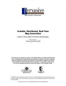
Fig. 16. Chip layout of the 2PW-1HW MAP processor (notation “1” and “2” denote the BMC and SMC, respectively).
dual-mode MAP processors are area-efficient accelerators to support the multistandard CTC decoding. B. Implementation of Prototyping Chip To decode the various CTC blocks of 3GPP and WiMAX standards, the 2PW-1HW MAP processor is implemented in a core size of 1.28 mm ASIC with 125 MHz operating frequency. of the proposed dual-mode 2PW-1HW The pipeline stage MAP processor is seven. The layout and summary of the prototyping chip are shown in Fig. 16 and Table VII, respectively. The MAP processor employs the radix-4 dual-mode EML-MAP decoding, and is obtained by using Verilog HDL codes synthesized with the standard cell library of TSMC 0.13 m CMOS process. The memory build-in-self-test circuits and scan chain insertions of the design-for-test scheme are implemented as well. In PW mode, the proposed MAP processor achieves throughput rate of 500 Mb/s@125 MHz with power of 97.83 mW. In HW mode, the proposed MAP processor achieves throughput rate of 250 Mb/s@125 MHz with power of 74.95 mW. The throughput rates are evaluated on a single MAP processor without considering the decoding latency. The power consumptions are estimated by Synopsis PrimePower on post-layout gate-level simulations with 2-dB SNR noisy data which are extracted from a high-level CTC simulation model. C. Comparisons Table VIII shows the comparisons of the MAP processors. The works in [16] and [33] perform the radix-2 and radix-16 SW MAP decoding, respectively. It is hard to compare various
works since coding parameters are different from each other. However, we use normalized energy efficiency (NEE) NEE
Power Throughput
Normalized energy factor
(17)
as one performance index. The NEE indicates how much energy a decoder chip consumes to process a hard bit. Besides, we use normalized area efficiency (NAE) NAE
Throughput Area Frequency
Normalized area factor (18)
as the other performance index. The NAE indicates how for a single CTC block a demany hard bits per one coder chip decodes. When we normalize the works from 0.18 to 0.13 m technology, the normalized energy factor is 1.2 V 1.8 V 0.13 m 0.18 m . Similarly, the 0.18 m 0.13 m . The normalized area factor is prototyping chip achieves a NEE of 0.19 nJ/bit and a NAE of 3.13 bits/mm in PW mode, and a NEE of 0.30 nJ/bit and a NAE of 1.56 bits/mm in HW mode. Note that the NEE and NAE are not to justify which design is superior to the others, but to provide an evaluative method for reference. D. Applications of the Prototyping Design Finally, several dual-mode 2PW-1HW MAP processors are used to decode the WiMAX and 3GPP CTC blocks for a verification of the multistandard systems. The throughput rates are , , and 125 MHz. derived from (5) based on Fig. 17 summarizes the requirements of the CTC decoding and the corresponding throughput rates by using the dual-mode 2PW-1HW MAP processors. For the WCDMA, HSDPA, and
Authorized licensed use limited to: National Taiwan University. Downloaded on July 12,2010 at 08:28:40 UTC from IEEE Xplore. Restrictions apply.
This article has been accepted for inclusion in a future issue of this journal. Content is final as presented, with the exception of pagination. LIN et al.: AREA-EFFICIENT SCALABLE MAP PROCESSOR DESIGN
13
1 = 7, f = 125 MHz, and I = 5).
Fig. 17. Applications of the prototyping dual-mode 2PW-1HW MAP processor design ( TABLE IX SUMMARY OF THE PROTOTYPING DUAL-MODE 2PW-1HW MAP PROCESSORS FOR THE CTC DECODING (AT 125 MHZ, 1.2 V, AND 5 ITERATIONS)
Mobile WiMAX, the required throughput rates are lower than 15 Mb/s. In this case, only one dual-mode 2PW-1HW MAP processor is configured to achieve the throughput rates with the 138.3 kb external SRAM and the corresponding on-the-fly CTC interleavers [6], [34]. Moreover, the throughput rates for Fixed WiMAX and LTE are 75 and 100 Mb/s, respectively. Hence, five dual-mode 2PW-1HW MAP processors are configured to achieve the throughput rates with the 150.0 kb external SRAM and the corresponding on-the-fly CTC interleavers [6], [18]. For the programmable multistandard MPSoC platform shown in Fig. 1(d), five dual-mode 2PW-1HW MAP processors can be dynamically reconfigured to support the throughput requirements listed in Table I. The throughput rates, total area costs, and total power consumptions of the dual-mode 2PW-1HW MAP processors which are applied to the considered CTC decoding are summarized in Table IX. Fig. 18 shows the fixed-point simulated BER performance of the distinct CTC schemes decoded by the dual-mode 2PW-1HW MAP processors on additive white Gaussian noise (AWGN) and 100 000 randomly generated CTC channels with blocks. The coding gain losses caused by the MAP processors are less than 0.2 dB compared with floating-point simulated results. VII. CONCLUSION In this paper, an area-efficient scalable MAP processor design has been presented and implemented for the high-throughput multistandard CTC schemes. The 1PW-1HW, 2PW-1HW, and M2PW-1HW MAP processors were proposed to meet the
Fig. 18. Decoding performance of the coderate-1/3 CTC decoding by using the prototyping 2PW-1HW MAP Processor design under AWGN channels.
throughput requirement of CTC decoding with low hardware costs. Besides, the shared module design of dual-mode MAP decoding was described in detail to achieve low computational costs and low storages. The proposed MAP processor which employs radix-4 dual-mode 2PW-1HW MAP decoding has been implemented in a core size of 1.28 mm with 0.13- m CMOS process. Our MAP processor achieved high throughput rates with low energy efficiency and high area efficiency. For a programmable MPSoC multistandard platform, the five dual-mode 2PW-1HW MAP processors can be dynamically reconfigured to support the high-throughput multistandard CTC schemes. ACKNOWLEDGMENT The authors would like to thank National Chip Implementation Center (CIC) for technical support. REFERENCES [1] C. Berrou, A. Glavieux, and P. Thitimajshima, “Near Shannon limit error-correcting coding and decoding: Turbo codes,” in Proc. Int. Conf. Commun., 1993, pp. 1064–1070.
Authorized licensed use limited to: National Taiwan University. Downloaded on July 12,2010 at 08:28:40 UTC from IEEE Xplore. Restrictions apply.
This article has been accepted for inclusion in a future issue of this journal. Content is final as presented, with the exception of pagination. 14
IEEE TRANSACTIONS ON VERY LARGE SCALE INTEGRATION (VLSI) SYSTEMS
[2] “3rd generation partnership project (3GPP),” [Online]. Available: http://www.3gpp.org/ [3] C. Berrou and M. Jezequel, “Non-binary convolutional codes for turbo coding,” Electron. Lett., vol. 35, no. 1, pp. 39–40, Jan. 1999. [4] “Worldwide interoperability for microwave access (WiMAX),” [Online]. Available: http://www.wimaxforum.org/home/ [5] M. Bickerstaff, L. Davis, C. Thomas, D. Garrett, and C. Nicol, “A 24Mb/s radix-4 LogMAP turbo decoder for 3GPP-HSDPA mobile wireless,” in Proc. IEEE Int. Solid-State Circuits Conf. (ISSCC), 2003, pp. 1–10. [6] C.-H. Lin, C.-Y. Chen, and A.-Y. Wu, “High-throughput 12-Mode CTC decoder for WiMAX standard,” in Proc. IEEE Int. Symp. VLSI Des., Autom., Test (VLSI-DAT), 2008, pp. 216–219. [7] U. Ramacher, “Software-defined radio prospects for multistandard mobile phones,” IEEE Comput., vol. 40, no. 10, pp. 62–69, Oct. 2007. [8] T. Vogt and N. Wehn, “A reconfigurable ASIP for convolutional and turbo decoding in an SDR environment,” IEEE Trans. Very Large Scale Integr. (VLSI) Syst., vol. 16, no. 10, pp. 1309–1320, Oct. 2008. [9] O. Muller, A. Baghadadi, and M. Jezequel, “From parallelism levels to a multi-ASIP architecture for turbo decoding,” IEEE Trans. Very Large Scale Integr. (VLSI) Syst., vol. 17, no. 1, pp. 92–102, Jan. 2009. [10] L. R. Bahl, J. Cocke, F. Jelinek, and J. Raviv, “Optimal decoding of linear codes for minimizing symbol error rate,” IEEE Trans. Inf. Theory, vol. 20, no. 2, pp. 284–287, Mar. 1974. [11] J.-M. Hsu and C.-L. Wang, “A parallel decoding scheme for turbo decoders,” in Proc. IEEE Int. Symp. Circuits Syst. (ISCAS), 1998, vol. 4, pp. 445–448. [12] A. Worm, H. Lamm, and N. Wehn, “A high-speed MAP architecture with optimized memory size and power consumption,” in Proc. IEEE Workshop Signal Processing Syst. (SiPS), 2000, pp. 265–274. [13] C. Schurgers, F. Catthoor, and M. Engels, “Memory optimization of MAP turbo decoder algorithms,” IEEE Trans. Very Large Scale Integr. (VLSI) Syst., vol. 9, no. 2, pp. 305–312, Apr. 2001. [14] M. M. Mansour and N. R. Shanbhag, “VLSI architectures for SISO-APP decoders,” IEEE Trans. Very Large Scale Integr. (VLSI) Syst., vol. 11, no. 4, pp. 627–650, Aug. 2003. [15] S.-J. Lee, N. R. Shanbhag, and A. C. Singer, “Area-efficient highthroughput MAP decoder architectures,” IEEE Trans. Very Large Scale Integr. (VLSI) Syst., vol. 13, no. 8, pp. 921–933, Aug. 2005. [16] S.-J. Lee, N. R. Shanbhag, and A. C. Singer, “A 285-MHz pipelined MAP decoder in 0.18.um CMOS,” IEEE J. Solid-State Circuits, vol. 40, no. 8, pp. 1718–1725, Aug. 2005. [17] Z. Wang, Z. Chi, and K. K. Parhi, “Area-efficient high-speed decoding schemes for turbo decoders,” IEEE Trans. Very Large Scale Integr. (VLSI) Syst., vol. 10, no. 6, pp. 902–912, Aug. 2002. [18] Y. Sun, Y. Zhu, M. Goel, and J. R. Cavallaro, “Configurable and scalable high throughput turbo decoder architecture for multiple 4G wireless standards,” in Proc. IEEE Int. Conf. Appl.-Specific Syst., Arch. Processors (ASAP), 2008, pp. 209–214. [19] C.-Y. Chen, C.-H. Lin, and A.-Y. Wu, “High-throughput dual-mode single/double binary MAP processor design for wireless WAN,” in Proc. IEEE Workshop Signal Process. Syst. (SiPS), 2008, pp. 83–87. [20] P. Robertson, E. Villebrun, and P. Hoeher, “A comparison of optimal and sub-optimal MAP decoding algorithms operating in the log domain,” in IEEE Int. Conf. Commun. (ICC), 1995, pp. 1009–1013. [21] S. Papaharalabos, P. Sweeney, and B. G. Evans, “SISO algorithms = operations for turbo decoding,” Elecbased on combined tron. Lett., vol. 41, no. 3, pp. 142–143, Feb. 2005. [22] J. Vogt and A. Finger, “Improving the max-log-MAP turbo decoder,” Electron. Lett., vol. 36, no. 23, pp. 1937–1939, Nov. 2000. [23] Y. Ould-Cheikh-Mouhamedou, P. Guinand, and P. Kabal, “Enhanced Max-Log-APP and enhanced Log-APP decoding for DVB-RCS,” in Proc. 3rd Int. Symp. Turbo Codes, Sep. 2003, pp. 259–269. [24] A. J. Viterbi, “An intuitive justification and simplified implementation of the MAP decoder for convolutional codes,” IEEE J. Sel. Area Commun., vol. 16, no. 2, pp. 260–264, Feb. 1998. [25] G. Masera, G. Piccinini, M. R. Roch, and M. Zamboni, “VLSI architecture for turbo codes,” IEEE Trans. Very Large Scale Integr. (VLSI) Syst., vol. 7, no. 3, pp. 369–379, Aug. 1999. [26] E. Boutillon, W. J. Gross, and P. G. Gulak, “VLSI architectures for the MAP algorithm,” IEEE Trans. Commun., vol. 51, no. 2, pp. 175–185, Feb. 2003. [27] J. Kaza and C. Chakrabarti, “Design and implementation of low-energy turbo decoders,” IEEE Trans. Very Large Scale Integr. (VLSI) Syst., vol. 12, no. 9, pp. 968–977, Sep. 2004.
max max
[28] C.-M. Wu, M.-D. Shieh, C.-H. Wu, Y.-T. Hwang, and J.-H. Chen, “VLSI architectural design tradeoffs for sliding-window Log-MAP decoders,” IEEE Trans. Very Large Scale Integr. (VLSI) Syst., vol. 13, no. 4, pp. 439–447, Apr. 2005. [29] Li F.-M, C.-H. Lin, and A.-Y. Wu, “Unified convolutional/turbo decoder design using tile-based timing analysis of VA/MAP kernel,” IEEE Trans. Very Large Scale Integr. (VLSI) Syst., vol. 16, no. 10, pp. 1358–1371, Oct. 2008. [30] T.-H. T. C.-H. Lin and A.-Y. Wu, “A memory-reduced Log-MAP kernel for turbo decoder,” in Proc. IEEE Int. Symp. Circuits Syst. (ISCAS), 2005, pp. 1032–1035. [31] XiLinx IP Center, San Jose, CA, “Xilinx LogiCORE, IEEE 802.16e CTC Decoder Core,” 2006. [32] C.-H. Lin, C.-Y. Chen, A.-Y. Wu, and T.-H. Tsai, “Low-power memory-reduced traceback MAP decoding for double-binary convolutional turbo decoder,” IEEE Trans. Circuits Syst. I, Reg. Papers, vol. 56, no. 5, pp. 1005–1016, May 2009. [33] C.-H. Tang, C.-C. Wong, C.-L. Chen, C.-C. Lin, and H.-C. Chang, “A 952MS/s max-log MAP decoder chip using radix-4 4 ACS architecture,” in Proc. IEEE Asian Solid-State Circuits Conf. (A-SSCC), 2006, pp. 79–82. [34] M.-C. Shin and I.-C. Park, “Processor-based turbo interleaver for multiple third-generation wireless standards,” IEEE Commun. Lett., vol. 7, no. 5, pp. 210–212, May 2003.
2
Cheng-Hung Lin (S’05) received the B.S. degree in electronic engineering from Fu Jen Catholic University, Taipei, Taiwan, in 2002, the M.S. degree in electrical engineering from National Central University, Taoyuan, Taiwan, in 2004, and the Ph.D. degree from National Taiwan University, Taipei, Taiwan, in 2009. Currently, he is serving his one-year military duty in Taiwan. His research interests include the design of VLSI architectures and circuits for digital signal processing and communication systems.
Chun-Yu Chen (S’08) received the B.S. degree in electronic engineering from National Chiao Tung University, Hsinchu, Taiwan, in 2007, and the M.S. degree in electronic engineering from National Taiwan University, Taipei, Taiwan, in 2009. He is currently an Engineer with Silicon Motion Technology Corporation, Taipei, Taiwan. His research interests include the design of VLSI architectures and circuits for digital signal processing and communication systems.
An-Yeu (Andy) Wu (S’91–M’96) received the B.S. degree from National Taiwan University, Taipei, Taiwan, in 1987, and the M.S. and Ph.D. degrees from the University of Maryland, College Park, in 1992 and 1995, respectively, all in electrical engineering. From August 1995 to July 1996, he was a Member of Technical Staff (MTS) at AT&T Bell Laboratories, Murray Hill, NJ, working on high-speed transmission IC designs. From 1996 to July 2000, he was with the Electrical Engineering Department, National Central University, Taiwan. In August 2000, he joined the faculty of the Department of Electrical Engineering and the Graduate Institute of Electronics Engineering, National Taiwan University, where he is currently a Professor. His research interests include low-power/high-performance VLSI architectures for DSP and communication applications, adaptive/multirate signal processing, reconfigurable broadband access systems and architectures, and SoC platform for software/hardware co-design. Dr. Wu was a recipient of the A-class Research Award from National Science Council for four times. He has served on many technical program committees of IEEE international conferences, and was an Associate Editor of IEEE transactions. He is now the Associate Editor of the IEEE TRANSACTIONS OF CIRCUITS AND SYSTEMS—II: EXPRESS BRIEFS and the IEEE TRANSACTIONS ON SIGNAL PROCESSING.
Authorized licensed use limited to: National Taiwan University. Downloaded on July 12,2010 at 08:28:40 UTC from IEEE Xplore. Restrictions apply.