Artifacts and Pitfall Errors Associated With Ultrasound-Guided Regional Anesthesia. Part II: A Pictorial Approach to Understanding and Avoidance Brian D. Sites, M.D., Richard Brull, M.D., F.R.C.P.C., Vincent W. S. Chan, M.D., F.R.C.P.C., Brian C. Spence, M.D., John Gallagher, M.D., Michael L. Beach, M.D., Ph.D., Vincent R. Sites, M.D., Sherif Abbas, M.D., and Gregg S. Hartman, M.D.
T
he use of real-time ultrasound guidance in regional anesthesia is growing in popularity. Paramount to the successful and safe use of ultrasound is the appreciation and accurate interpretation of common ultrasound-generated artifacts. An artifact is any perceived distortion, error, or addition caused by the instrument of observation (signal processor).1 Imaging artifacts can be considered display phenomena, and, therefore, can potentially complicate the planned procedure. There are 4 generic categories of imaging artifacts:2 (1) Acoustic: error in presentation of ultrasound information; (2) Anatomic: error in interpretation (often called “pitfall” error); (3) Optical illusion: error in perception; and (4) Other: electrical noise. This article builds on the fundamental principles of ultrasound physics that are discussed in Part I of this article.3 The objective of this article is to describe and illustrate many of the acoustic and anatomic artifacts commonly encountered by the regional anesthesiologist. In the process, we will offer underlying physical explanations and describe practical tips on how to negotiate these often misleading phenomena.
From the Departments of Anesthesiology(B.D.S., B.C.S., J.G., M.L.B., G.S.H.) and Orthopedic Surgery (B.D.S.), Dartmouth Medical School, Dartmouth-Hitchcock Medical Center, Lebanon, NH; Department of Anesthesia and Pain Medicine (R.B., V.W.S.C., S.A.), Toronto Western Hospital, University of Toronto, Toronto, Ontario, Canada; and Department of Radiology (V.R.S.), Tufts University School of Medicine, Lahey Clinic, Burlington, MA. Accepted for publication May 18, 2007. Reprint requests: Brian D. Sites, M.D., Regional Anesthesia, Dartmouth-Hitchcock Medical Center, One Medical Center Drive, Lebanon, NH 03756. E-mail:
[email protected] © 2007 by the American Society of Regional Anesthesia and Pain Medicine. 1098-7339/07/3205-0011$32.00/0 doi:10.1016/j.rapm.2007.08.001
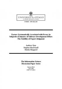
Acoustic Artifacts Acoustic artifacts associated with performing regional anesthesia can be further subdivided into 2 major categories: (1) Missing or falsely perceived structures; and (2) degraded images. The reader should note that different imaging artifacts may have the same underlying physical mechanism. Missing Structures or Falsely Perceived Objects Overgain and undergain artifacts. Inappropriately low gain settings may result in the apparent absence of an existing structure (i.e., “missing structure” artifact), whereas inappropriate high gain settings can easily obscure existing structures. Example 1: Figure 1 represents two identical images of the interscalene brachial plexus with the overall gain set too high (Fig 1A) and too low (Fig 1B). Example 2: The incorrect use of the time gain compensation (TGC) dials can create an image wherein existing structures appear absent. In Figure 2, the fourth TGC button was turned down too low, effectively abolishing the image of the nerve roots. When the TGC was set correctly (Fig 3), the C5 through C7 nerve roots can easily be seen. Clinical pearls: Gain adjustments are fraught with potential artifact generation. Take advantage of the ability to control overall gain levels and TGC. Adjust the gain settings to optimally define the structure of interest. The usual pattern of the TGC dials is depicted in Figure 3B, with a gradual increase in signal intensity; the near field gain is turned down and the far field gain is increased in a progressive fashion. Lateral resolution artifacts. Lateral resolution refers to the system’s ability to distinguish 2 objects from one another when they exist in a lateral to medial relationship. Example 1: Figure 4B demonstrates the common peroneal and tibial nerves as they appear in short
Regional Anesthesia and Pain Medicine, Vol 32, No 5 (September–October), 2007: pp 419 –433
419
420
Regional Anesthesia and Pain Medicine Vol. 32 No. 5 September–October 2007
Fig 1. Incorrect overall gain settings. This is a short axis view of the brachial plexus. (A) Overall gain set too high. (B) Overall gain set too low. AS, anterior scalene muscle; C5, C6, C7, the fifth through seventh cervical nerve roots; MS, middle scalene muscle.
axis in the popliteal fossa. Given that these structures are superficial, the system is set to a high frequency (12 MHz). In addition, the ultrasound beam is electronically focused (creating the narrowest beam as possible) at the exact depth of the nerves. The two nerves clearly appear as separate hyperechoic structures. Figure 4A demonstrates what happens when the frequency is reduced (8 MHz) and the beam is incorrectly focused proximal to the neural structures. Now the neural images appear less like 2 distinct structures due to the degradation in lateral (and axial) resolution. Figure 5 demonstrates the degradation in the resolution of the popliteal sciatic nerve with incorrect focus settings.
Fig 2. Incorrect use of the time gain compensation dials. (A) The ultrasound image is the short axis view of the interscalene brachial plexus. The nerve roots are now apparently missing. The arrow points to the band of hypoechoic tissue created by the incorrect use of the fourth time compensation button. (B) Note that the fourth time gain compensation dial is turned down, creating the band of undergain that eliminates the C5, C6, and C7 nerve roots. AS, anterior scalene muscle; MS, middle scalene muscle.
Fig 3. The correct time gain compensation (TGC) settings. (A) The C5 through C7 nerve roots are now easily seen with the TGC settings. (B) The diagonal arrow indicates the typical pattern for the TGC dials, with a progressive increase (right shift) for the deeper structures. AS, anterior scalene muscle; MS, middle scalene muscle.
Clinical pearls: Electronically focus the ultrasound beam on the structure of interest. Select the highest frequency probe that still allows adequate penetration to the depth of the structure of interest. Many ultrasound machines have the ability to generate multiple focal zones for the simultaneous imaging of several structures at different depths. Acoustic shadowing. Acoustic shadowing occurs when a structure has a larger attenuation coefficient than the tissue that lies deep to it, causing the deeper tissue to appear far less echogenic than normal. Acoustic shadowing occurs most notably when seeking a target that lies deep to bone. The appreciation of acoustic shadowing is critical to the performance of safe and effective ultrasound-guided regional anesthesia. We will therefore present 5 examples spanning the spectrum of regional anesthesia. Example 1: This is a case of acoustic shadowing caused by bone during spinal imaging in preparation for a neuraxial blockade. The acoustic shadow generated by the adult spinous process impedes the penetration of the ultrasound waves, resulting in the inability to reliably visualize the ligamentum flavum, epidural space, and dura (Fig 6). The larger intervertebral spaces combined with less densely ossified childhood bone cause less acoustic shadowing and enable visualization of these important structures.4 Clinical pearls: The acoustic shadows produced by the spinous processes and lamina can help the operator identify the midline when performing neuraxial blockade, especially in obese patients. The operator may opt for needle insertion either above or below the level of any spinous process. Traditional endpoints for confirmation of correct needle location into the epidural or intrathecal space should always be employed. Example 2: Acoustic shadowing created by the first rib in the supraclavicular region. Acoustic shadow-
Ultrasound-Generated Artifacts
•
Sites et al.
421
Fig 4. This image demonstrates the impact of lateral resolution on the ability to image the common peroneal nerve (CP) and tibial nerve (TN) in short axis in the popliteal fossa. (B) A short axis image of these nerves. The frequency is set at 12 MHz because the structures are superficial. The beam is electronically focused at the depth of the neural structures. Note that you can clearly delineate 2 separate nerves. (A) Inaccurate imaging of the same structures, which were easily seen in (B). In this image, the frequency was reduced to 8 MHz and the focus was placed superficial to the nerves. The arrowheads indicate the two nerves. The arrows indicate the focal zone (narrowest point) of the ultrasound beam.
ing can lead to the erroneous assumption that there exist no structures of interest in an anechoic (black) region. In the performance of a supraclavicular nerve block, the goal of the ultrasound exam is to visualize the subclavian artery, the first rib, and the trunks or divisions of the brachial plexus. The important structure to avoid contact with is the pleura which should exist immediately below the first rib. However, because the rib shields the pleura from the ultrasound beam, no anatomical information is provided (Fig 7). Clinical pearls: Never insert the needle into the anechoic region deep to the first rib because the location of the pleura cannot be identified. Example 3: Acoustic shadowing created by air during local anesthetic injection. In this dramatic case of acoustic shadowing, a popliteal sciatic nerve block was aborted secondary to the presumed dam-
Fig 5. This is the short axis image of the sciatic nerve in the popliteal fossa showing the impact of the focus on image quality of a single structure. In (A), with the focus set correctly, the sciatic nerve is well defined. In (B), the focus is set incorrectly, thereby greatly degrading the image. The focus location is indicated by the {. With this particular system, there are multiple focal zones, explaining the three icons on the right side of the screen.
age to the sciatic nerve. Fig 8 shows the sciatic nerve before the injection. Fig 9 shows the nerve after 10 mL of local anesthetic was injected. The sciatic nerve appears to have been physically dissected in half. The most likely explanation for this acoustic shadow is an air bubble located at the tip of the needle. In the video loop of this block, when the needle is removed from the patient, the nerve appears to suddenly reform (see Appendix, Video 1). A small amount of air serves as the perfect medium to generate a dropout shadow, as air does not conduct ultrasound.
Fig 6. Ultrasound image of the structures seen in the lumbar region during the performance of an ultrasoundguided epidural placement. The bony structures, namely the spinous process (SP) and the lamina (L) act as strong specular reflectors. Ultrasound is unable to pass through the bone and a hypoechoic acoustic shadow (drop out) is thus generated deep to the bone. This precludes the ability to easily image the spinal cord. TP, transverse process.
422
Regional Anesthesia and Pain Medicine Vol. 32 No. 5 September–October 2007
Fig 7. Ultrasound image of the structures seen during the performance of a supraclavicular nerve block. Note that although it is very easy to visualize the subclavian artery (SA), the nerves, and the first rib, one cannot image the pleura or lung. This is because the first rib acts like a specular reflector and a complete acoustic shadow (drop out) occurs deep to the rib. The arrows indicate the divisions of the brachial plexus.
Clinical pearls: When you suspect that the anatomy is erroneous secondary to needle or air-induced acoustic shadowing, simply move the needle or reposition the probe slightly to allow the ultrasound waves to bypass the obstruction from air or metal. Further, the operator should pay careful attention to remove all air from the injection syringes. Example 4: This is an example of acoustic shadowing created by a 19-gauge needle during an outof-plane approach to place a continuous femoral nerve catheter. In this example, the needle crossed the ultrasound beam in a perpendicular manner creating a linear acoustic shadow transecting the
Fig 8. Ultrasound image of the sciatic nerve as seen in short axis in the popliteal fossa. The nerve appears as a large and round hyperechoic structure. The triangles indicate the needle as it is approaching the nerve.
Fig 9. After 10 ml of local anesthetic injection, the nerve appears to split in half. An acoustic shadow was most likely generated by an air bubble at the needle tip. This acoustic shadow is easy to see passing right through the nerve and into the anterior tissues.
nerve (Fig 10). This acoustic shadow is helpful because it tells the operator that the needle is correctly aligned in the lateral-medial plane. However, because the exact location of the needle tip is unknown (in the anterior-posterior plane), an alternative endpoint for injection or catheter threading is necessary (such as nerve stimulation). Clinical pearls: Search for an acoustic shadow (transecting the target nerve) when inserting a needle using the out-of-plane technique. This will help to confirm the correct lateral-medial location of the needle relative to the target nerve. The operator should appreciate the limitations of the out-of-plane technique, primarily,
Fig 10. Ultrasound image of the infrainguinal structures as seen in short axis. There is an acoustic shadow (arrow) associated with the needle being advanced using the outof-plane technique. The nerve appears falsely to have been separated into 2 structures. The dropout shadow is an indication that the needle tip or shaft has crossed the ultrasound beam. FA, femoral artery; FV; femoral vein; N, femoral nerve.
Ultrasound-Generated Artifacts
the inability to confirm the real-time exact location of the needle tip. See Figure 6 of Part I3 for the comparison of in-plane versus out-of-plane techniques. Example 5: Acoustic shadowing may not only hide important structures or distort normal anatomy (as in examples 1-4), it may also be a sign of serious patient pathology. For example, calcified arterial plaques act as strong specular reflectors that generate distinct acoustic shadows deep to the affected artery. Because most ultrasound-guided nerve blocks make use of the intimate association of nerves and blood vessels as an important reference point, the regional anesthesiologist will inevitably be confronted with the primary discovery of vascular pathology. In addition, if a transarterial technique is contemplated, one may wish to choose another approach if acoustic shadowing is identified related to a blood vessel of interest. Figure 11 shows an acoustic shadow associated with an atherosclerotic plaque of the right femoral artery discovered during the placement of a single injection femoral nerve block. Figure 12 shows another acoustic shadow associated with an atherosclerotic lesion of the right carotid artery discovered during the placement of an interscalene catheter. The hyperechoic plaque is also well visualized. Clinical pearls: If an acoustic shadow is identified related to a blood vessel, further clinical evaluation may be needed to assess for significant vascular disease. This may be most important for patients in whom the regional anesthesiologist may traumatize the blood vessel during the performance of the nerve block. Acoustic enhancement. Acoustic enhancement occurs when a region behind a weakly attenuating structure produces stronger echoes than
Fig 11. Ultrasound image of the femoral artery in short axis showing an atherosclerotic lesion. This pathology was identified during the performance of a femoral nerve block. Note the hyperechoic plaque and the acoustic shadow. Calcium deposits in the plaque act as strong specular reflectors. FA, femoral artery.
•
Sites et al.
423
Fig 12. Ultrasound image of the carotid artery in long axis showing an atherosclerotic lesion. This pathology was identified during the performance of an interscalene catheter. Note the hyperechoic plaque and the characteristic acoustic shadow.
those observed from adjacent tissues. Enhancement artifacts commonly occur when ultrasound waves pass relatively unattenuated through blood vessels (weak attenuators), resulting in false enhancement of the adjacent deeper tissue. Because many peripheral nerves are associated with large blood vessels, acoustic enhancement is a common finding. Examples 1 and 2: Enhancement artifact in the region of the infraclavicular and axillary brachial plexus can be most misleading as the tissue immediately behind the posterior wall of the axillary artery often appears very hyperechoic and is easily mistaken for either the radial nerve (axillary block; Fig 13) or the posterior cord (infraclavicular block; Fig 14). Clinical pearls: Because acoustic enhancement can make it difficult to definitively visualize either the radial nerve or the posterior cord of the brachial plexus, it may be important to use an additional confirmation technique such as nerve stimulation. Absent blood flow when blood flow actually exists. Doppler is an important technology in screening for vascularity of a region. However, as is true for 2-dimensional imaging, the assessment of blood flow has the potential for artifact generation. The major concern for the regional anesthesiologist is to falsely conclude that a structure is not a blood vessel when no flow is seen. As explained in Part I,3 Doppler technology allows for the assessment of both velocity and directionality of blood flow. The complicating factor is that for accurate analysis, blood flow should be parallel to the ultrasound beam.5 This is based on the Doppler equation (Part I, Fig 63). In most cases, the regional anesthesiologist is imaging blood vessels on short axis, and,
424
Regional Anesthesia and Pain Medicine Vol. 32 No. 5 September–October 2007
Fig 13. Ultrasound image of the structures in short axis as seen in the axillary fossa. Acoustic enhancement of the tissue immediately posterior to the blood vessel is indicated by the arrow. This hyperechoic area can easily be mistaken for the radial nerve (R) which is actually lying adjacent to the artery. A, axillary artery; M, median nerve; MCN, musculocutaneous nerve; U, ulnar artery.
therefore, the blood flow is completely perpendicular to the ultrasound beam. As the angle of incidence of the beam and the blood flow approaches 90 degrees, the cosine of this angle approaches zero (see Doppler equation3), thereby creating an artifact of no flow. Clinical pearls and example: Figure 15 shows the left carotid artery and internal jugular vein (IJ) as imaged on short axis in the mid neck. Figure 15A reveals no blood flow in the IJ, whereas Figure 15B clearly suggests blood flow. The only difference between Figures 15A and B is that the probe handle was tilted slightly cephalad, thus changing the angle of incidence (between the ultrasound beam and the blood flow) from near 90 degrees to less than 90 degrees. This change in angulation allows for maximal return (to the probe) of the ultrasound waves that have shifted frequency (i.e., Doppler shift). This Doppler shift is represented as blood flow on the screen display. The operator should note that the appearance of blood flow will also be dependent on the scale set to evaluate velocities and the color gain settings. In this example, the scale was set at 10 cm/s which is a relatively low setting for a large artery. Low scales and higher color gain will tend to increase the sensitivity to detect flow.
Needle reverberation artifact. Example 1: Although there are many reverberation artifacts described in the cardiac literature7 the most relevant reverberation artifact for the regional anesthesiologist involves 2 specular reflectors: the probe itself and the block needle. A depiction of an 18gauge needle inserted in-plane with the ultrasound beam is elsewhere in this issue (Part I, Fig 5A3). Under the needle are seen multiple and equally spaced linear densities that represent ultrasound waves bouncing back and forth within the lumen of the needle. When the ultrasound energy finally returns to the probe to be processed, a duplicate image of the needle will be displayed on the screen. This duplicate image will appear deeper than the primary (actual) needle because more time has elapsed for the ultrasound energy to return to the probe. The mechanism of the reverberation artifact is depicted in Figure 16. Example 2: Figure 17 illustrates the in-plane approach for a musculocutaneous nerve block. The needle is inserted through the biceps muscle. Due to a reverberation artifact involving the needle, the 22-gauge b-bevel needle appears larger than it should. In addition, the exact tip location is obscured secondary to this size discrepancy. Clinical pearls: Reverberation artifacts occur to a larger degree when the needle is completely perpendicular to the ultrasound beam. Therefore, if the angle of incidence is adjusted to less than 90 degrees, there will be less artifact (illustrated in Fig 5B of Part I3). The operator should keep in mind that as the needle becomes less perpendic-
Degraded Images Image degradation may be the result of user interface issues, but can often be the result of a phenomenon known as reverberation. Reverberations occur as the result of ultrasound waves bouncing back and forth between two strong specular reflectors. The result is usually multiple linear and hyperechoic areas emanating distal to the reflecting structures. When multiple reverberation artifacts are merged, this has been referred to as the comet tail sign.6
Fig 14. Ultrasound image of the structures in short axis as seen in the infraclavicular fossa. Acoustic enhancement of the tissue posterior to the blood vessel can be seen. This generates confusion as to the exact location of the posterior cord (P) of the brachial plexus. A, axillary artery; L, lateral cord; M, medial cord; PMa, pectoralis major muscle; PMi, pectoralis minor muscle; V, axillary vein.
Ultrasound-Generated Artifacts
•
Sites et al.
425
Fig 15. Ultrasound image of the short axis view of the internal jugular vein (IJ) being analyzed with color flow Doppler. (A) There appears to be no blood flow in the IJ. This artifact was generated because the angle of incidence between the ultrasound beam and the blood flow approached 90 degrees. Blood flow, however, can be visualized by tilting the probe handle toward the patient’s head. This will create an angle of incidence greater than 90 degrees, and some blood flow will be revealed (B). CA, carotid artery.
ular to the ultrasound beam, the needle shaft will also become more difficult to visualize. The other helpful tactic is to reduce the far gain in an effort to darken the duplicate images of the needle.
Fig 16. Reverberation artifact, detailed in a stepwise manner. Each number above the needle (top) has a corresponding number on the ultrasound screen (bottom) to graphically represent the result of different reverberation events. The original ultrasound beam contacts the needle and is reflected back to the probe correctly (1). In addition, part of the ultrasound beam penetrates the hollow needle and is reflected back to the probe from the distal wall of the needle (2). However, a component of the ultrasound beam becomes “stuck” within the needle lumen because the needle walls are highly reflective barriers. This signal component is reflected between the needle walls several times before “escaping” back to the probe (3), (4). Thus, the probe interprets these later occurring signals as objects distal to the needle at intervals which are multiples of the needle diameter.
Tissue reverberation artifact. Example 1: Multiple reverberations generated by the pleura in the infraclavicular region can produce a comet tail sign (Fig 18A). Hyperechoic streaks (“comets”) emanating from a strong specular reflector such as the pleura should alert the provider that the planned point of entry is too medial or that the plane of imaging is too oblique, thereby prompting the repositioning of the probe prior to needle insertion. Figure 18B is an example of the comet tail sign associated with the subclavian artery identified during a supraclavicular block. Example 2: A linear artifact is generated when a linear tissue plane participates in a reverberation process which generates a reproduction of the
Fig 17. Ultrasound image of the musculocutaneous nerve (N) imaged in short axis in axillary fossa. The needle (only a 22-gauge b-bevel) can be seen in long axis just anterior to the nerve. The reverberation artifact makes the needle appear larger than it is and obscures the exact tip location. Local (L) anesthesia can be seen surrounding the nerve. The triangles indicate the needle location.
426
Regional Anesthesia and Pain Medicine Vol. 32 No. 5 September–October 2007
image deep to its actual location. Figure 19 represents the performance of an interscalene nerve block. The C5 nerve root can be easily visualized prior to injection (Fig 19A). Postinjection (needle not present), there appears to be a physical structure now present within the center of the C5 nerve root (Fig 19B). This artifact most likely resulted from a reverberation process associated with the relative echogenicity of a fascial layer above the brachial plexus. Following the injection of local anesthesia, the ultrasound waves are now reflected back and forth between this fascial layer and another specular reflector (most likely the probe itself). The end result is the depiction of the fascial layer at an erroneous position through the C5 nerve root. Clinical pearls: The comet tail sign (example 1) can be helpful as an alert to the provider that a strong specular reflector (e.g., bone or pleura) exists in the region of the proposed needle trajectory. To help confirm that a suspicious structure is a reverberation artifact, increase the pressure applied to the probe against the skin. This pressure application should move (or eliminate) a linear artifact to a more superficial location (because the distance to the primary specular reflector has been decreased). Following probe pressure in example 2, the artifact disappeared. If there truly were a lesion within the C5 nerve root, then it would still appear at the original location within the C5 nerve root.
Fig 18. (A) The comet sign visualized during preparation for an infraclavicular blockade. The streaks (“comets”) indicated by the arrows represent the convergence of multiple reverberations generated by the first rib imaged obliquely in the infraclavicular region. The unlabeled arrow indicates the comet tail. Slight repositioning of the probe to the sagittal plane causes these artifacts to disappear. (B) Classic comet tail sign involving structures commonly seen during a supraclavicular block. AA, axillary artery; AV, axillary vein; PL, pleura; PMJ, pectoralis major; SA, subclavian artery.
Fig 19. (A) Ultrasound image of the interscalene brachial plexus imaged in short axis during the performance of an interscalene nerve block. Only the fifth cervical nerve root (C5) is visualized. Prior to the injection, the C5 nerve root was visualized and appeared normal. (B) Following injection, there appeared to be a new structure within the center of the nerve root. This represents a linear artifact generated by a reverberation event involving a more hyperechoic structure anterior to the nerve root. With the application of probe pressure, the artifact disappeared. MS, middle scalene; SCM, sternocleidomastoid muscle.
Example 3: “Double-barreled subclavian artery.” A similar artifact has been reported in the cardiac ultrasound literature for the aorta. Ultrasound may bounce back and forth within the lumen of an artery, generating a duplication of the 2-dimensional image of the subclavian artery with the artifact existing deep to the actual structure. This duplication will also occur with Doppler flow. Figure 20 shows a mirror image artifact involving the subclavian artery seen during the performance of a supraclavicular block. Clinical pearls: When performing a supraclavicular block, neural structures should be found adjacent to the more superficial (nonartifact) artery. If a needle is in-
Fig 20. A reverberation artifact showing a duplication of the subclavian artery (SA) found during a supraclavicular block. The artifact exists for both the 2-dimensional image and the Doppler analysis. The artifact is the structure that is more posterior.
Ultrasound-Generated Artifacts
Fig 21. Ultrasound image of the sciatic nerve (SN) in the popliteal fossa imaged in short axis. The hyperechoic round sciatic nerve can easily be seen. The needle is inserted from the lateral aspect of the patient. As the needle enters the perineural adipose tissue, it appears to bend in an anterior fashion. This artifact is generated by the subtle differences in the velocity of ultrasound in adipose and muscle tissue. The arrowheads indicate the needle. The arrow indicates the bending point on the needle.
serted towards the deeper (artifact), a pneumothorax will likely ensue. Bayonet artifact. The term Bayonet artifact was coined by Gray et al.8 and first reported with respect to a transarterial axillary plexus block. An example of a Bayonet artifact is illustrated in Figure 12 captured during a popliteal sciatic block performed with the patient in the supine position. The needle is inserted in-plane and almost completely perpendicular to the ultrasound beam. The ultrasound image suggests that the needle itself appears broken or bent. This degraded image artifact is generated due to the subtle differences in the speed of ultrasound in various biological tissues. Although we generally assume that ultrasound travels at 1,540 meters per second inside the human body, the reality is that ultrasound wave velocity varies slightly with different tissues.9 In Figure 21, the needle travels through muscle and into the adipose tissue surrounding the sciatic nerve. The apparent bend in the needle occurs because the speed of ultrasound in adipose tissue is slower than that in the surrounding muscle. Therefore, the needle appears to bend away (anterior) from the probe. When ultrasound velocity is reduced, it takes longer for the waves to return to the probe. Based on the basic formula of distance equals velocity multiplied by time, the machine will register the part of the needle in the adipose tissue as deeper than the part of the needle in the muscle. This creates the bending appearance. The direction of the bend in the needle
•
Sites et al.
427
is opposite to that presented by Gray8 in which the needle bends toward the probe, because the speed of ultrasound in blood is faster than in the surrounding nerve sheath. Probe-skin artifact. Because air does not conduct ultrasound, the probe faceplate must fully contact the skin without any interfacing air. This is the reason that a conductive gel is often placed between the probe faceplate and the skin. Two situations can arise that generate significant dropout. The first case can occur when only a portion of the probe footprint is able to make contact with the skin due to size mismatch between the breadth of the footprint and the anatomical region to be imaged, as commonly occurs during tibial nerve block at the ankle or ulnar nerve block at the wrist. The latter is illustrated in Figure 22. This may preclude the ability to image the progress of the needle if it is inserted from the side of the dropout shadow. When complete contact is made between the entire probe footprint and the skin (Fig 23), the dropout shadow is eliminated. The second case of dropout can occur when air pockets are contained between the plastic probe cover and the probe footprint. Clinical pearls: Careful probe positioning, appropriate probe selection, and placement of generous amounts of ultrasound transmission gel should eliminate most of the skin-to-probe dropout artifacts. Anatomic Artifacts Anatomic artifacts are tissue structures– either normal or aberrant–that may resemble the target nerve and thus mislead the operator into pursuing the wrong target. These errors in interpretation are often referred to as “pitfall errors.” The common solutions to all pitfall errors are to: (1) trace the target nerve along its expected anatomic course; and (2) use a peripheral nerve stimulator as an adjunct to confirm the target’s identity.
Fig 22. The incorrect position of the probe on the skin (A) can generate a large dropout shadow (B) which could complicate the performance of an ulnar nerve (UN) block in the mid forearm. UA, ulnar artery.
428
Regional Anesthesia and Pain Medicine Vol. 32 No. 5 September–October 2007
Tendons and Muscles Chief among the pitfall errors is mistaking a tendon for the target nerve. The ultrasound appearance of nerves and tendons can appear indistinguishably similar. With experience, the ultrasonographer will appreciate the subtle hyperechoic continuous fibrils that comprise a tendon compared with the hypoechoic fascicles inside a nerve.10 Flexor tendons can be easily mistaken for the median nerve when performing a distal forearm median nerve block as depicted in Figure 24. In the forearm, the tendons appear more irregular and less oval in comparison with the median nerve. Muscles can confuse the performance of an ultrasound-guided nerve block as well. This commonly occurs in the popliteal fossa. The common peroneal, tibial, and sciatic nerves have very similar ultrasound appearances when compared with the surrounding biceps femoris, semitendinosus, and semimembranosus muscles. One can appreciate this similarity in Figure 25, depicting an image of the popliteal fossa after the division of the sciatic nerve. The operator can easily distinguish the nerve from the surrounding muscle by appreciating the interpositioned adipose tissue (indicated in Fig 25). Adipose tissue is more hypoechoic than either the nerve or the muscle, and, therefore, creates a discernable interface. In our experience, the most challenging popliteal blocks to perform are in athletes with well developed muscles and little adipose tissue. The sciatic nerve of an athlete as imaged proximally in the popliteal fossa is shown elsewhere in Figure 3 of Part I.3 The difficulty in distinguishing the sciatic nerve from the surrounding muscle is due to the paucity of surrounding adipose tissue.
Fig 23. The correct way to place the probe on the skin (A) to generate a complete image without dropout (B). The is important because the needle is commonly inserted in-plane from the ulnar (i.e., medial) side of the probe. In situations similar to Figure 23, the approaching needle may not be visualized. UA, ulnar artery; UN, ulnar nerve.
Fig 24. Ultrasound image of the median nerve (N) imaged in short axis in the distal forearm. Note the similarity in echogenicity of the tendons and nerve. The triangles indicate the tendons. The nerve becomes rounder and separates from the tendons as the probe is moved more proximally in the arm.
Muscles can actually be confused for major blood vessels. Figure 26 shows the anatomy commonly encountered during a supraclavicular approach to the brachial plexus. In this patient, a structure appears in long axis situated anterior to the brachial plexus. Due to the tubular and anechoic appearance, this structure appears virtually identical to a large caliber blood vessel. This structure is the inferior belly of the omohyoid muscle and Doppler interrogation will reveal no blood flow. The inferior belly of the omohyoid muscle is a helpful landmark in localizing the nerves which usually lie just posterior to the muscle.
Fig 25. Short axis ultrasound images of the structures found in the popliteal fossa including the common peroneal (CPN) and the tibial (TN) nerves. Note the similarity of the nerves to the surrounding muscle. The only aspect of this image that supports the ability to identify the nerves is the small layer of adipose tissue that separates muscles from nerves. BFM, biceps femoris muscle; STM, semitendinosus muscle.
Ultrasound-Generated Artifacts
•
Sites et al.
429
Blood Vessels Blood vessels are not usually mistaken for nerves because there are several key identifying features that differentiate one from the other. In general, nerves are echogenic, whether hypoechoic or hyperechoic relative to the surrounding tissue, while blood vessels are uniformly anechoic structures. Second, arteries can be seen to pulsate and resist compression. Conversely, veins do not pulsate and are easily compressible. Importantly, nerves appear nonpulsatile and are not compressible. Finally, color Doppler can detect blood flow within an imaged structure, thereby positively identifying it as a blood vessel. Color Doppler may be especially important to help differentiate artery from nerve when performing an ultrasound-guided interscalene brachial plexus blockade. Unlike most other nerves in the body, the roots of the brachial plexus can appear perfectly round and anechoic. A small caliber noncompressible artery in the neck may be dangerously mistaken for a nerve root, as evidenced in Figure 27. In this case, color Doppler promptly identified the hazardous vascular structure. In addition, the supraclavicular block in Figure 28 and Video 2 (see Appendix) was aborted in favor of an infraclavicular block secondary to anomalous hypervascularity surrounding the brachial plexus.
Fig 26. Short axis view of the brachial plexus and subclavian artery in the supraclavicular fossa. The triangles outline an anechoic structure resembling a large blood vessel imaged in long axis. This structure is actually the inferior belly of the omohyoid muscle. The divisions of the brachial plexus are sandwiched between the omohyoid muscle anteriorly and the first rib posteriorly, as indicated in the cartoon. A, subclavian artery.
Fig 27. (A) The interscalene brachial plexus imaged in short axis. Color Doppler interrogation (B) revealed that what we thought was the C5 nerve root was actually a small artery (noncompressible with light probe pressure).
Sometimes, however, even color Doppler can fail to identify a blood vessel, as was the case in Figure 29, which depicts a thrombosed internal jugular vein. A thrombosed vein is noncompressible with internal hypoechoic shadows, not dissimilar from the appearance of a nerve. Whenever basic maneuvers (compression), defining features (internal echogenicity), and color Doppler fail to identify a structure of interest, the operator must remember to trace the structure proximally and distally as well as use a nerve stimulator for definitive confirmation. In addition, it is useful to scan the anticipated path of the needle with color Doppler prior to needle insertion. This will help (as in Figure 28) to
Fig 28. Short axis view of the supraclavicular fossa. Screening with color flow Doppler is an important safety addition to any nerve block. Here we discovered unexpected and anomalous arterial vascularity. This vascularity was not appreciated until we scanned the area with color Doppler. The procedure was aborted and changed to an infraclavicular block. A, subclavian artery.
430
Regional Anesthesia and Pain Medicine Vol. 32 No. 5 September–October 2007
Fig 29. An occluded internal jugular vein found during the performance of an interscalene nerve block. Color Doppler flow demonstrated no flow and the vessel did not compress with light probe pressure. Note the hyperechoic thrombus found in the normally anechoic lumen. CA, carotid artery.
identify any unnamed and unsuspected vascular structures. Lymph Nodes For the regional anesthesiologist, inflamed lymph nodes may complicate ultrasound-guided peripheral nerve blockade in the cervical, axillary, and inguinal regions. There are several sonographic features that can help to differentiate lymph nodes from nerves. Inflamed lymph nodes are generally large noncompressible, well circumscribed, round anechoic structures with small internal hypoechoic
oval-shaped opacities, which are representative of intranodal necrosis.11 Figure 30 depicts inguinal lymphadenopathy incidentally encountered upon performing a femoral nerve block in a patient presenting for a total knee arthroplasty. Upon recognition of the lymphadenopathy, the operators decided to perform a single injection procedure instead of the originally planned continuous femoral nerve catheter. Figure 31 shows a lymph node that was initially mistaken for a venous thrombosis involving the saphenous vein in the infrainguinal region. Finally, lymph nodes have a very similar appearance to nerves in the axilla and as such can confound the performance of an ultrasound-guided axillary block. In these situations a nerve stimulator may be indispensable to physiologically distinguish a lymph node from nerve. Nerves How can we be fooled by the target nerve itself? Commonly, the operator can easily identify the target nerve in a particular location, but while manipulating the probe to optimize the image quality, the nerve suddenly disappears. There are 2 explanations for this apparent vanishing act. First, peripheral nerves are highly mobile structures that can change position with even small amounts of pressure routinely applied to administer a peripheral nerve block. This phenomenon was aptly described by Retzl and colleagues who demonstrated the varying location of the median nerve relative to the axillary artery with gentle pressure applied by the ultrasound probe.12 Further, text-
Fig 30. Ultrasound appearance of lymphadenopathy found in the inguinal region during the performance of a femoral nerve block. Lymph nodes (LN) often have a heterogeneous ultrasound appearance. They may be round, oval, and have septi (as in this case). They can easily be confused for neural tissue or occluded veins (Fig 31).
Ultrasound-Generated Artifacts
Fig 31. Ultrasound appearance of an inguinal lymph node discovered during the performance of a continuous femoral nerve catheter. We originally believed this structure to be an occluded saphenous vein. However, patency of the saphenous vein was later confirmed. The anechoic outer ring of the lymph node (indicated by the arrows) represents perinodal edema, whereas the more echogenic interior represents the soft tissue aspects of the node. FA, femoral artery.
books traditionally designate the area posterior to the axillary artery as the location of the radial nerve, but ongoing experience with ultrasound is teaching us that the location of the radial nerve is highly variable. Further, as Figure 32 shows, the ulnar nerve is often located at a significant distance from the axillary artery. In this patient, the ulnar nerve was 3.5 cm away from the axillary artery during the performance of an axillary block. Nerve stimulation was used to confirm that this was truly the ulnar nerve.
Fig 32. Ultrasound appearance of the axillary brachial plexus as imaged in short axis. The operator identified the ulnar nerve 3.5 cm away from the axillary artery (a). Due to this distance from the artery, nerve stimulation was used to confirm that this structure was truly the ulnar nerve (U). M, median nerve.
•
Sites et al.
431
Secondly, there is the issue of reflection and refraction of ultrasound energy. The only way an image can be displayed on the ultrasound screen is if ultrasound reflects off of a nerve and successfully returns to the probe. If a significant portion of the ultrasound energy bounces off of the nerve and is transmitted away from the probe, then the image of the nerve will either be degraded or completely missing. Figure 33 shows how subtle angulations of the probe can either degrade or optimize the neural image. The amount of ultrasound reflected or refracted depends on the angle at which the ultrasound beam hits the interface between different objects (media). As the angle of incidence nears 90 degrees (perpendicular to the structure of interest), a higher percentage of reflected ultrasound successfully returns to the probe. Therefore, the operator should sweep the beam through an arc to try to generate a situation which optimizes the image. Edema The regional anesthesiologist performing extremity blocks will inevitably encounter patients with significant peripheral edema. This edema may physically distort the neural anatomy (depth change), mask hypoechoic structures, dilute the local anesthetic injection, and possibly alter nerve stimulation thresholds. Figure 34 shows mid calf edema in a patient having a mid calf saphenous nerve block. In this case the operators were unable to find the saphenous nerve or saphenous vein due to the severity of the edema. Alternatively, edema may sometimes facilitate the image localization of a nerve. That is, a nerve that appears primarily hyperechoic (e.g., sciatic), may become prominently outlined by the hypo-
432
Regional Anesthesia and Pain Medicine Vol. 32 No. 5 September–October 2007
echoic edema fluid. This is analogous to the injection of ultrasound contrast media to facilitate nerve localization or cardiac imaging.13
Conclusion Knowledge of ultrasound related artifacts is an exciting educational opportunity for the regional anesthesiologist. At the very least, these artifacts are nuisances and provoke intellectual curiosity. At the very worst, a misinterpretation of an ultrasoundgenerated artifact may result in a negative patient outcome. It should be emphasized that as our community’s experience grows with these relatively new techniques, there will undoubtedly be additions to this preliminary database of artifacts. Our anecdotal and collective experiences are that the appreciation of the existence, the understanding of the mechanisms, and the recognition of the
Fig 34. Ultrasound appearance of the soft tissues of the mid calf during the performance of a saphenous nerve block. Because the ultrasound approach to the saphenous nerve block relies in the visualization of the greater saphenous vein, edema (indicated by arrows) can compound this block by obscuring the landmark vein. Edema has the same anechoic appearance as any vein. This procedure was aborted.
appearances of the aforementioned artifacts supports the efficient and safe conduct of ultrasoundguided regional anesthesia.
Appendix Supplementary material (video files) Supplementary videos can be found in the online version of this article at www.rapm.org (doi: 10.1016/j.rapm.2007.08.001).
References
Fig 33. Short axis view of the ulnar nerve in the mid forearm. The angle of incidence between the ultrasound beam and the nerve is important for optimal imaging. Subtle angulations can result in dramatic variations in image quality. The right hand side of the Figure depicts a situation where a subtle tilting motion of the probe results in degradation of the image, presumably from a reduction in effective reflection and an increase in refraction. The left hand side of the figure represents the ideal situation with optimal imaging. The white arrow indicates the ulnar nerve.
1. Webster’s Online Dictionary. Available at http://www. websters-online-dictionary.org/definition/artifact. Accessed May 1, 2007. 2. Kremkau F, Taylor K. Artifacts in ultrasound imaging. J Ultrasound Med 1986;5:227-237. 3. Sites BD, Brull R, Chan VWS, Spence BC, Gallagher J, Beach ML, Sites VR, Hartman GS. Artifacts and pitfall errors associated with ultrasound-guided regional anesthesia. Part I: Understanding the basic principles of ultrasound physics and machine operations. Reg Anesth Pain Med 2007;32:412-418. 4. Rapp HJ, Folger A, Grau T. Ultrasound-guided epidural catheter insertion in children. Anesth Analg 2005;101:333-339. 5. Perinno A, Reeves S, eds. A Practical Approach to Transesophageal Echocardiography. Philadelphia: Lippincott Williams & Wilkins; 2003:77-92. 6. Thickman DI, Ziskin MC, Goldenberg NJ, Linder BE. Clinical manifestations of the comet tail artifact. J Ultrasound Med 1983;2:225-230. 7. Blanchard DG, Dittrich HC, Mitchell M, McCann HA. Diagnostic pitfalls in transesophageal echocardiography. J Am Soc Echocardiogr 1992;5:525-540.
Ultrasound-Generated Artifacts 8. Gray AT. Bayonet artifact during ultrasound-guided transarterial axillary block. Anesthesiology 2005;102: 1291-1292. 9. Anderson ME, McKeag MS, Trahey GE. The impact of sound speed errors on medical ultrasound imaging. J Acoust Soc Am 2000;107:3540-3548. 10. Silvestri E, Martinoli C, Derchi LE, Bertolotto M, Chiaramondia M, Rosenberg I. Echotexture of peripheral nerves: correlation between US and histological findings and criteria to differentiate tendons. Radiology 1995;197:291-296.
•
Sites et al.
433
11. Ahuja A, Ying M. Grey-scale sonography in assessment of cervical lymphadenopathy: review of sonographic appearances and features that may help a beginner. Br J Oral Maxillofac Surg 2000;38: 451-459. 12. Retzl G, Kapral S, Greher M, Mauritz W. Ultrasonographic findings of the axillary part of the brachial plexus. Anesth Analg 2001;92:1271-1275. 13. Goldberg BB, Liu JB, Forsberg F. Ultrasound contrast agents: a review. Ultrasound Med Biol 1994;20:319333.