Journal of Theoretical and Applied Information Technology 15 August 2012. Vol. 42 No.1 © 2005 - 2012 JATIT & LLS. All rights reserved.
ISSN: 1992-8645
www.jatit.org
E-ISSN: 1817-3195
OPTIMAL SETTING GAIN OF PSS-AVR BASED ON PARTICLE SWARM OPTIMIZATION FOR POWER SYSTEM STABILITY IMPROVEMENT 1,2
MUHAMAD HADDIN, 2SOEBAGIO, 2ADI SOEPRIJANTO, 2MAURIDHI HERY PURNOMO 1 Electrical Engineering Department, Sultan Agung Islamic University, Semarang, Indonesia 2 Electrical Engineering Department, Institut Teknologi Sepuluh Nopember, Surabaya, Indonesia E-mail:
[email protected],
[email protected],
[email protected],
[email protected] ABSTRACT
This paper presents the settings of automatic voltage regulator (AVR) and power system stabilizer (PSS) on a single machine infinite bus (SMIB) to improve the dynamic stability of the power system. This setting is done by determining the fitness function of AVR (K A ) and PSS (K PSS ) gain using Particle Swarm Optimization (PSO) algorithm. The main purpose of this setting is to minimize the oscillation frequency so that it would improve the stability of electric power. Simulations are conducted by inputting step function with 5% load fluctuations as a representation of dynamic load. Simulation results show that the proposed method is very effective for improving the damping of electromechanical oscillations of the power system. The proposed method shows that the power system produces a reduced rate of 11% overshoot and settling time 40%. Keywords: Setting Gain of PSS-AVR, Dynamic Stability, Modified PSO
1. INTRODUCTION Generally, the power system stabilizer (PSS) design methods involve the frequency response based on the concept of increasing the damping torque. PSS is equipment used to improve dynamic stability. PSS will function properly when set appropriately. Tuning of PSS provides the appropriate characteristics of phase-lead and compensates the phase-lag between the reference input of the AVR and electrical torque oscillation frequency outside the specified range, so that the components of electrical torque in phase with the variation of velocity for improved damping. PSS has a very significant contribution to maintaining stability in power systems and improve system performance by providing additional signals to the excitation system. This is a very easy, economical, practical and flexible for power system stability improvement. The development of integrated control of synchronous generator has been developed by most researchers to improve the electrical stability include in: continually online trained artificial neural network (COT-ANN) with back propagation algorithm to control the excitation and governor [1]-[2]. Design of generator control with PSS and
excitation has been done by using the dual heuristic programming (DHP) and the heuristic dynamic programming (HDP) based multi layer perceptron (MLP) and radial basis function (RBF) [3]-[6], [8], genetic algorithms [7], recurrent neural networks [9], fuzzy logic [10]-[11]. However, these studies focused on the improvement of stability by PSS. This paper applied the method of Particle Swarm Optimization to simultaneously settings gain of PSS-AVR which can improve the dynamic stability of power system.
2. DESIGN AND METHODOLOGY Power system consists of electrical power components which form an integrated system. There are three essential components of the electric power system generation, transmission and load. Equivalent circuit of a synchronous generator connected to the grid is represented as a single machine infinite bus (SMIB). Configuration of the interconnected generator interconnected with the load impedance is represented in Figure 1.
42
Journal of Theoretical and Applied Information Technology 15 August 2012. Vol. 42 No.1 © 2005 - 2012 JATIT & LLS. All rights reserved.
ISSN: 1992-8645
www.jatit.org
E ’
G
E-ISSN: 1817-3195
EB
Infinite Bus
1
KPSS
f
Zeq
Gain PSS
Tw.s
T1.s+1
Tw.s+1
T2.s+1
Washout
1 Vs
Lead/lag
Fig.1. Model of SMIB
Fig.3. Model of Power System Stabilizer
2.1. Automatic Voltage Regulator (AVR) AVR function is to keep the generator voltage at fixed nominal value. Model AVR depends on the type of DC current injection source to the excitation system. An important part of the AVR consists of amplifiers, exciter, excitation voltage limiters, generators, and transducers. AVR transfer function can be written as in Eq.(1).
PSS is the equipment that generates control signals for excitation and turbine system and works to increase the limit of stability with a set of generator excitation to provide damping to the rotor of the synchronous oscillations. To improve the damping, the PSS must produce electrical torque component on a machine that has the same phase. This method can improve the performance of the power system stability. Linear modeling of governor-turbine system at the show in Figure 4. Governor-turbine system used in this research consisted of the speed drop, governor, servomotor, and reheater.
VR ( s ) KA = Vc ( s ) 1 + sTA
(1)
where V R (s), V C (s), K A and T A are the output amplifier, control signal, amplifier gain and time constant interval, respectively. Parameter values have special values between 10-400 pu and 0.02-0.1 s for the K A and T A , respectively. Excitation system voltage is limited by using a limiter to avoid over excitation or under excitation. Linier model of AVR in exitation system is shown in Figure 2.
1
KA Gain AVR
1
1
TA.s+1
TE.s+1
AVR
Saturation 1
Exciter
1 Saturation 2
Fig.2. Model of AVR in excitation system
2.2. Power System Stabilizer (PSS) Dynamic stability of the power system is determined by the ability of generators to respond to load changes that occur are relatively small (5%). Load changes that occur suddenly and periodically can not be responded by generator so that it can affect the stability. This response causes the frequency oscillation in the long term and cause a decrease in the transfer of power to the electric power system. This problem can be covered by using additional equipment called Power System Stabilizer (PSS). Linear model of PSS is shown in Figure 3.
T
1
-1/R Speed Droop
KG
U
R
B
I
N
Tg1.s+1
1
1
FTg5.s+1
Tg2.s+1
Tg3.s+1
Tg4.s+1
Tg5.s+1
Servo Motor
Entrained Steam
Reheater
PREF Gain G O V E R N O R Saturation
E
1
Fig.4. Model of governor turbine
SMIB linear models equipped with AVR and PSS are shown in Figure 5. 2.3. Particle Swarm Optimization Development of PSO algorithm is done based on the behavior of individuals in the particle swarm [12]. PSO algorithm searches in parallel with use of a similar group of individuals with other artificial intelligence based heuristic optimization techniques. Form of n-dimensional search space, position and velocity of individual i is represented as a vector X i = (x i1 ,…,x in ) and V i = (v i1 ,…,v in ) in Pbest
the PSO algorithm. If Pbesti = ( xi1 and Gbest =
Gbest Gbest ( x1 , ..., xn )
Pbest
, .., xin
)
is individual i who
is the current best position. Update the velocity on individual i is to modify the basic equation of the PSO algorithm Vi
43
k +1
k k k k k = wVi + c1rand1 ( Pbesti − X i ) + c2 rand 2 ( Pbesti − X i ) (1)
Journal of Theoretical and Applied Information Technology 15 August 2012. Vol. 42 No.1 © 2005 - 2012 JATIT & LLS. All rights reserved.
ISSN: 1992-8645
www.jatit.org
E-ISSN: 1817-3195
PSS
Delta Vs
Delta wr
1
K4 K4 Tm1 Delta Omega1
Governor
1
Flux
K3
In1 VF
Te
1
wo
2*Hs+KD
s
K2
K3*Td0aksen.s+1 Field circuit Exiter K6
2
K2 K6
K1
2 PL
K1
Voltage transducer
K5
1
K5
TR.s+1
1 k k +1 Fig.5. Linear model of SMIB withk +PSS-AVRAGC
X i = X i +Vi
(3)
One of the simplest dynamical system which shows where: chaotic behavior of an iterator is called map Vik = velocity of individual i at k iteration function shown in Eq.(4). w = parameter of weight (4) = f k µ . f k −1 .(1 − f k −1 ) c 1 , c 2 = coefficient of acceleration rand1, rand2 = number of random between 0and 1 where μ is the control parameter and has a real k value between 0-4. Xi = position of individual i at k iteration The basic equation of PSO algorithm is modified P best ik = P best individual i until k iteration (MPSO) by using inertia weight approach (IWA) as shown in Eq.(1)-(3). Inertia weight is introduced k G best = G best group until k iteration i to balance ability between global and local. Equation (4) is obtained by a combination of In the process of updating this velocity, the values inertia weigth and chaotic sequences with the new of parameters such as w, c 1 and c 2 should be value of inertia weight according to Eq.(5). determined in advance. Weight parameter w is obtained by using the following Eq.(2). (5) W=wf k
= w wmax −
wmax − wmin Itermax
xIter
(2)
where: w min , w max = weight of initial and final = number of max iteration Iter max Iter = number of iteration now Each individual moves from an initial position to the next position by modifying the position of the individual by using a modified of velocity according to Eq.(1). While the modification of individual positions expressed in Eq.(3)
PSO algorithm: 1. Initialize a population of candidate solutions at random particles, i.e. the position and velocity of particles. 2. Calculating the fitness value for each particle. 3. From the results of the calculation value of fitness, the best fitness known locally is the best fitness value for each particle and the local best position that is the best position of each particle. The current fitness value is compared to the previous fitness value. If the value is better so the change of the previous particle positions with the current position has a better fitness value and the fitness value becomes the reference of the next fitness value. 44
Journal of Theoretical and Applied Information Technology 15 August 2012. Vol. 42 No.1 © 2005 - 2012 JATIT & LLS. All rights reserved.
ISSN: 1992-8645
www.jatit.org
4. Finding the global best fitness value, namely a minimum value of the local best fitness. 5. Determining the global best position. This is obtained by replacing each candidate particle solutions with local best position of particles that meet the requirements of the global best fitness. 6. Updating the velocity and position 7. Repeating steps 2 through 6 to comply with the specified Linear modeling of SMIB equipped an PSS and AVR linear models are combined and is represented in the Eq.(7) and (8). By using the matrix A of the linear model of SMIB the value of the eigenvalue obtained by using Eq.(9). Gain settings of AVR (K A ), and gain setting of PSS (K PSS ) is done by calculating the eigenvalue of the matrix A. Eigenvalue can be shifted to the negative real by finding the maximum value of damping ratio for each eigenvalue are possible. Search the maximum value of damping ratio equal to find the minimum value of the comprehensive damping index (CDI). Eq.(10) is a formula of the CDI is used as the fitness function of the particle in the optimization process. By minimizing Eq. (11), eigenvalue power system can be shifted to the negative real.
E-ISSN: 1817-3195
position of the particle with d-dimensional problem space. Figure 6 shows the structure of the particle consists of three regions of the problem search space of each particle. Each particle consists of the AVR gain (K A ) and PSS (K PSS ). Optimization algorithm is shown in Figure 7.
n min = f ( z ) = CDI = ∑ (1 − ζ i ) i =1
KA
(12)
K PSS
Fig.6. The structure of each particle in PSO
Start
Input Parameter of SMIB
Initialization Population of PSO
Caculate The Eigenvalue System
Objective Function: n min = f ( z ) = CDI = ∑ (1 − ζ i ) i =1
∆x = A ∆x + B ∆u ∆y = C ∆x + D ∆u
(7) (8)
Local Best Fitness
λi = σ i + jωi n CDI = ∑ (1 − ζ i ) i =1 −σ i ζi = σ i2 + ωi2
(9)
Local Best Position
(10)
Global Best Fitness Iter=iter +1 Global Best Position (gbest)
(11)
where ∆x , ∆y , ∆u ,A, B, C, D, λi , σ i , ωi , ζ i are state variable, output variable, input variable, matrix system, matrix input, matrix output, i-th eigenvalue, real part of the i-th eigenvalue, real imaginer part of the i-th eigenvalue and damping ratio of the i-th, respectively. Parameter in the lead-lag block and washout in PSS was defined, while setting the gain of the AVR (K A ), and PSS (K PSS ) optimized using the MPSO. Eq. (12) showed that MPSO method using CDI as fitness and gain value allowed as a delimiter in the optimization process. In addition to the two values of gain, the value of damping ratio is also used as a limiting factor. CDI is a function of z. z is the row matrix element which is the gain of the AVR (K A ) and PSS (K PSS ). In the PSO method, z is called the
Update velocity using Equation 1 Update velocity using Equation 2
No
Max iteration Yes
Optimum Gain: KA, KPSS
Stop
Fig.7. PSO algorithm flow chart
3. RESULT AND ANALYSIS Simulations performed using Matlab 7.1 was applied to the system to provide dynamic stability performance information based on the rotor speed, rotor angle, electrical torque and terminal generator on the SMIB with the parameters shown in table 5. 45
Journal of Theoretical and Applied Information Technology 15 August 2012. Vol. 42 No.1 © 2005 - 2012 JATIT & LLS. All rights reserved.
ISSN: 1992-8645
www.jatit.org
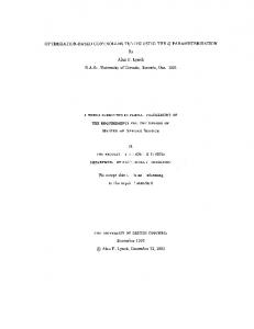
Figure 8 shows that the global minimum of fitness particle is achieved at 20th iteration. This shows that the minimum value of the CDI can be achieved in the 20th iteration.
0
Deviation of rotor angle (p.u)
With PSS-AVR
2.8
2.6
-2
PSS-AVR Optimized By PSO
-3
-4
-5
-6
-7
-8
2.4
-9
0
1
2
3
4
5
6
7
8
9
10
Time (s)
2.2
Fig.10. Response of rotor angle deviation
CDI (minimum)
2
6
1.8
1.6
0
5
10
15
20
25
30
35
40
45
Deviation of electric torque (p.u)
CDI (Comprehensive Damping Index)
Open loop
-1
3
50
Iteration
Fig.8. Graphics CDI as a function of iteration
Figure 9, 10, 11, and 12 showed that the response of the rotor speed deviation, rotor angle, electrical torque, and the terminal generator of the SMIB. Deviation of the response rotor speed, rotor angle, electrical torque, and the terminal generator of the SMIB with AVR and PSS settings showed an improvement of the response without the use of setting the AVR-PSS and open loop.
PSS-AVR Optimized By PSO
0
-2
-4
0
1
2
3
4
5
6
7
8
9
10
Fig.11. Response of electric torque deviation 1.4
Open loop
Open loop With PSS-AVR
0.04
With PSS-AVR 2
Time (s)
Deviation of terminal voltage (p.u)
0.06
Open loop
4
-6
0.08
Deviation of rotor speed (p.u)
E-ISSN: 1817-3195
PSS-AVR Optimized by PSO 0.02
0
1.2
With PSS-AVR PSS-AVR Optimized By PSO
1
0.8
0.6
0.4
0.2
-0.02 0
-0.04
0
1
2
3
4
5
6
7
8
9
10
Time (s)
-0.06
Fig.12. Response of terminal voltage deviation
-0.08
-0.1
-0.12
0
1
2
3
4
5
6
7
8
9
Time (s)
Fig.9. Response of rotor speed deviation
10
Simulation results in Figure 9, 10, 11 and 12, showed that the gain settings of the PSS-AVR based on MPSO can improve the performance or response of the deviation of rotor speed, rotor angle, electrical torque and terminal voltage of the generator so that the resulting improvement of power system stability. Overshoot and settling time in a state of open-loop, setting the PSS-AVR and optimized with MPSO are shown in Tables 1 and 2. This suggests that the gain settings of PSS-AVR based on MPSO able to reduce the overshoot and steady state speed up.
46
Journal of Theoretical and Applied Information Technology 15 August 2012. Vol. 42 No.1 © 2005 - 2012 JATIT & LLS. All rights reserved.
ISSN: 1992-8645
www.jatit.org
Table 1. Overshoot (p.u) With PSS-VR
PSS-AVR Based MPSO
-0.1183
-0.05938
-0.05248
-8.852
-7.218
-6.493
Open loop ∆ω ∆δ ∆Pe
5.62
4.039
2.933
∆Vt
1.091
1.276
1.184
[3]
[4]
[5] Table 2. Settling time (s) Open loop
With PSSAVR 3.173 3.361
PSS-AVR Based MPSO 2.227 2.397
∆ω ∆δ
5.077 4.609
∆Pe
4.953
2.676
1.546
∆Vt
3.986
3.639
2.584
Table 1 shows that the decrease in rotor angle overshoot on the open-loop conditions and using the PSS-AVR based MPSO is 36%, while using the PSS-AVR and PSS-AVR based MPSO is 11%. Table 2 shows that the difference in settling time reduction of rotor angle in a state open loop using the PSS-AVR based MPSO is 92% and using the PSS-AVR with PSS-AVR based MPSO is 40%.
[6]
[7]
[8]
[9]
4. CONCLUSION Modified Particle Swarm Optimization (MPSO) can be applied for setting gain of PSS (K PSS ) and AVR (K A ),. Tuning method is able to reduce the of comprehensive damping index (CDI) of SMIB. Minimum value of CDI produced can be achieved at the 20th generation. The proposed method is proved improving response of the the dynamic stability power system to reach steady state compared with no arrangement and open loop.
[10]
[11]
REFERENCES: [1] Kumar, G. and R. Harley, “A Continually Online Trained Artificial Neural Network Identifier for a Turbo generator”, Proceedings of the International Joint Conference on Neural Network. 1999. [2] Kumar, G. and R. Harley, “Two Separate Continually Online-Trained Neuro-controllers for Excitation and Turbine Control of a
[12]
47
E-ISSN: 1817-3195
Turbo generator”, IEEE Trans.On Industry Application, 38(3), 2002, pp.887-893. Park, J.W. and R. Harley, “Adaptive Critic Based Optimal Neuro-control for Synchronous Generator in a Power System Using MLP/RBFNN”, IEEE Trans. On Industry Applications, 39(5), 2003, pp.261269. Park, J.W. and R. Harley, “Indirect Adaptive Control for Synchronous Generator: Comparison of MLP/RBFNN Approach with Lyapunov Stability Analysis”, IEEE Trans. On Neural Networks, 15(2), 2004, pp.460464. Park, J.W. and G. Kumar, “Multilayer Perceptron Neural Network Based Online Global Model Identification of Synchronous Generator”, IEEE Trans. On Industrial Electronics, 52(6). 2005 Liu, W., Venayagamoorthy, and G.K. Wunsch, “Adaptive Neural Network Based Power System Stabilizer Design”, Proceedings of the International Joint Conference On Neural Networks, July, 2003. Dubay, M. and P. Gupta, “Design of GeneticAlgorithm Based Robust Power System Stabilizer”, International Journal of Computational Intelligence, Vol.2, 2006. Park, J.W. R. Harley, and G. Jang, “Dual Heuristic Programming Based Optimal Control for a Synchronous Generator”, Elsevier Engineering Applications of Artificial Intelligence, Vol.21, 2008. Chen, C.J. and T. Chen, “Design Of A Power System Stabilizer Using A New Recurrent Network”, International Journal of Innovative Computing, Information and Control (ICIC), 3(4), 2007, pp.97-105. Taher, S.A. and Shemshadi, “Design Of Robust Fuzzy Logic Power System Stabilizer”, Proceeding Of World Academy Of Science, Engineering And Technology, 21(5), 2007. Corcau, J.I. and E. Stoenescu, “An Adaptive PID Fuzzy Controller for Synchronous Generator”, WSEAS International Conference on Systems, Greece, July, 2008, pp.434-437. Ebenhart, R. and Kennedy, “Particle Swarm Optimization”, Proc. IEEE Inter Conference on Neural Networks, Perth, Australia, Piscataway, NJ, 4, 1995, pp.1942–1948.
Journal of Theoretical and Applied Information Technology 15 August 2012. Vol. 42 No.1 © 2005 - 2012 JATIT & LLS. All rights reserved.
ISSN: 1992-8645
www.jatit.org
E-ISSN: 1817-3195
APPENDIX Table 3. Parameter of PSO Parameter MPSO Number of particle maximum iteration Number of dimention C 1 (Cognitive constants) C 2 (Social constants) w max w min
Table 4. Parameters of K A , K PSS
µ
20 50 2 2.05 2.05 0.9 0.4 0.4
f k −1
0.75
KA 400 245.2207
Before optimization After optimization
K PSS 3 3.3634
Table 5. Parameter of SMIB Parameter
Value
Parameter
Value
Parameter
Value
Parameter
Value
Parameter
Value
K1
1.591
KD
0
KA
400
F
0,322
Vt0
1
K2
1,5
T1
0,4
Tw
0,5
TA
0,01
iq0
1
K3
0,333
T2
0.3
H
3,0
VAMIN
-1
Xd
1,6
K4
2
T3
1,91
Ks
2,191
TMMIN
0
Xc
1,6
K5
0,12
TR
0,02
Tg1
0,0264
VFMIN
-1
Td0’
K6
0,3
KPSS
3
Tg3
0,15
fo
50
Tg4
0,594
VAMAX
1
KG
20
Tg5
2,662
TMMAX
Tg2
0,0264
TE
0
VFMAX
48
Eq0
6
1,05
Ki
0,05
R
1
XE
0,4
1,2
Eb
1
Xd’
0,32
1
Xq
1,55
Ed0
1