Artificial Neural Network-based error compensation procedure for low-cost encoders. V.K.Dhar, A.K.Tickoo, S.K.Kaul, R.Koul, B.P.Dubey
†
Astrophysical Sciences Division, Electronics and Instruments Services Division, Bhabha Atomic Research Centre, Mumbai-400 085,India.
arXiv:0911.3717v1 [cs.NE] 19 Nov 2009
†
Abstract : An Artificial Neural Network-based error compensation method is proposed for improving the accuracy of resolver-based 16-bit encoders by compensating for their respective systematic error profiles. The error compensation procedure, for a particular encoder, involves obtaining its error profile by calibrating it on a precision rotary table, training the neural network by using a part of this data and then determining the corrected encoder angle by subtracting the ANNpredicted error from the measured value of the encoder angle. Since it is not guaranteed that all the resolvers will have exactly similar error profiles because of the inherent differences in their construction on a micro scale, the ANN has been trained on one error profile at a time and the corresponding weight file is then used only for compensating the systematic error of this particular encoder. The systematic nature of the error profile for each of the encoders has also been validated by repeated calibration of the encoders over a period of time and it was found that the error profiles of a particular encoder recorded at different epochs show near reproducible behaviour. The ANN-based error compensation procedure has been implemented for 4 encoders by training the ANN with their respective error profiles and the results indicate that the accuracy of encoders can be improved by nearly an order of magnitude from quoted values of ∼± 6 arc-min to ∼±0.65 arc-min when their corresponding ANN-generated weight files are used for determining the corrected encoder angle.
Key Words : Resolver based encoder, Error compensation, Artificial Neural Network. email:
[email protected]
1
1. Introduction : A resolver [1,2] is an electromechanical device which converts shaft angle to an absolute analog signal. The construction of a resolver is similar to that of an AC electric motor with two sets of phase windings acting together as a variable phase transformer, whose output analog voltage represents the input shaft angle uniquely. On excitation by a signal, one of the sense windings of the resolver develops a voltage proportional to the sine of the rotor displacement angle and the other develops a voltage proportional to the cosine of this angle. A complete encoder system is built by coupling a resolver to an excitation source and phase angle monitoring circuit known as resolver-to-digital (R/D) converter [3]. The conversion of the resolver signal to position is achieved by using a tracking loop which monitors the phase lag between the actual and measured position. Resolvers have been available for a few decades in various forms as part of electromechanical shaft angle position measurement systems. They are robust, reliable and have a long life even while working in severe and harsh environments. High reliability and lower price compared to optical encoders makes resolver-based encoders an ideal choice for applications involving moderate accuracies of ∼10 arc-min. Keeping in view the fact that, in reality, no resolver can generate ideal sinusoidal signals because of the manufacturing tolerances, it is obvious that low-cost resolvers will be available with only modest accuracies. The non-ideal characteristics of a resolver have been discussed thoroughly in the seminal work of Hanselman [4,5] and it is now very well established that the most important contributors to the error profile budget are the following: (i) Amplitude imbalance, (ii) Quadrature error, (iii) Inductive harmonics, and (iv) Excitation signal distortion. The non-ideal characteristics of a resolver arise because of the finite precision with which a resolver can be mechanically constructed and the nonideal nature of the excitation signal. While low-cost resolvers are available with accuracy values of about ±10 arc-min, improvement in their accuracy requires maintaining stringent tolerance limits in their manufacture, which can add to the cost considerably. The easiest way to reduce or compensate position error due to mechanical misalignments and imperfections in the signal outputs of a resolver is to calibrate it against a higher accuracy sensor so that the integrated systematic error profile of the resolver along with its R/D converter can be measured and then compensated by using a suitable procedure. The results of our software-based compensation work, using the look up table approach [6] and Fourier-series based method [7] also confirm that the accuracy of low-cost, resolver based 16bit encoders can indeed be improved from quoted accuracy ∼± 6 arc-min to ∼ ± 0.65 arc-min. The main aim of the present work is to study the feasibility of using Artificial Neural Network for predicting the error profile of encoders so that appropriate correction can be applied to the measured values of the encoder angle for determining the corrected encoder angle. Since all the resolvers will not have exactly similar error profiles becaue of the inherent differences in their construction, the ANN needs to be trained on one error profile at a time. Hence, corresponding to each encoder, there is a unique ANN-generated weight file which one has to use for compensating the systematic error.
2
Summary of some compensation applications Precision motion systems play an important and direct role in the industry. In these systems involving automated positioning machines and other machine tools, the relative position errors between the machine and the work piece directly affect the quality of the final product or the process concerned. No matter how well the machine may be designed and manufactured, these error sources are inevitable in any motion system and hence there is an inherent limit to the achievable accuracy on these machines. While, careful design and precise mechanical construction can reduce these errors, error modeling and compensation is a highly viable option in improving the system performance further at a much reduced cost. The basic motivation behind the compensation is to measure the magnitude of inaccuracy and compensate it through various compensation methods. As long as the errors are systematic, repeatable and measurable, they can be compensated by using appropriate techniques. Conventionally, compensation methods utilize mechanical correctors, leadscrew correction etc. for improving accuracy. However, these devices increase the complexity of the machine and over a period of time, due to wear and tear, degrade the error compensation. More so, even these corrective components have to be monitored, serviced, calibrated or even replaced on a regular basis resulting in higher costs and downtime. Software based error compensation methods include use of fuzzy error interpolation techniques, neural-based approaches, genetic algorithms, finite element analysis and Multi-variant Regression analysis. All of these methods work on a static geometric model of the machine errors, which are obtained (or derived) from measurements of the machine with reference standards at various predetermined points. With the present day error compensation methods, the conventional limits on accuracy of machine tools can be overcome significantly [8]. A great deal of work in the recent past has gone in identification and elimination of sources of error in machine systems. The machine manufacturers are now able to achieve better accuracies on account of improved design followed by an appropriate error compensation methodology. The use of ANN methodology in error compensation has been reported in many studies for various applications. A feed-forward neural network employing 11:15:5 model (11 inputs, 15 hidden nodes and 5 outputs) has been used to predict five thermally induced spindle errors with an accuracy better than ±15% [9]. Heng-Ming Tai et al [10] have used an ANN based algorithm for tracking control of industrial drive systems. Although several tracking control techniques like sliding mode, variable structure, self-tuning and model reference adaptive controls have been used but ANN based tracking controls have been found to be ideally suited for this application. Using a backpropagation based ANN algorithm, the authors of the above work claim that the ANN based controller can achieve real time tracking of any arbitrary prescribed trajectory with a higher degree of accuracy. The idea of using ANN based models for physical systems has also been explored by several other researchers [11-17] to understand the characteristics of inverse dynamics of controlled systems . An ANN based approach has been used for error compensation of machine tools also [18]. Important sources of error in CNC machine tools are the geometric motions of the individual machine elements along with the thermal errors which cause
3
these geometric errors to vary over time. A three-layer feedforward network with 2 inputs (corresponding to x and z coordinates in the workspace), 2 outputs (corresponding to position error components) and 12 nodes in the hidden layer has been employed by them for machine error compensation. The results of their study demonstrate that substantial improvements in positioning accuracy are obtained through the use of ANN methodology. It is also emphasized in this work that the algorithm would however fail if tested on another machine with different error characteristics. K.K.Tan et al [19] have applied ANN based compensation for geometrical errors for coordinate measuring machines (CMM) to minimize the position error between end-effector and workpiece. Measurement of encoder error profiles Some of the main specifications of the single turn 16-bit encoders , which are used in the present study, are the following [20]: Make — CCC,USA; Model – HR 90-11; Size — NEMA 12; Resolution — ∼0.33 arc-min (16-bit); Accuracy — ±6.0 arc-min. Eight such encoders are being presently used in the 4-element TACTIC (TeV Atmospheric Cherenkov Telescope with Imaging Camera) array of atmospheric Cherenkov telescopes [21]. Each telescope of the array uses two encoders for monitoring its zenith and azimuth angle so that the drive control software [22] can be operated in a closed-loop configuration for tracking a celestial source. The calibration of the encoders was carried out with a Rotary Table of a Coordinate Measuring machine ( Make: Zeiss, Germany; Model : RT 05 -300). The Rotary Table has a resolution of ∼0.5 arc seconds and an accuracy of ∼2 arc seconds [23]. The calibration procedure involves rotating the resolver shaft in a 2◦ step and recording the decoded resolver angle value alongwith the corresponding Rotary Table angle value. The calibration data of a particular encoder, which is needed for training the network, thus consists of a data file of 180 values of the decoded resolver angles and the corresponding Rotary Table angles. The decoded resolver angles were recorded at Rotary Table angle values of 0◦ , 2◦ , 4◦ , 6◦ , ....... , 358◦ . Although the overall error profile of a encoder system is expected to be dominated by the non-ideal characteristics of the resolver, the error contribution from the decoder (comprising the excitation signal source, R/D converter and angle read out circuitry) cannot be completely ignored, more so, when the excitation signal source itself is contained in the decoder. Since using a single resolver with two different decoder units indicated that for the same resolver angle (as measured by the Rotary Table) there can be a mismatch of ∼2 arc-min between the two decoders, we have treated a particular resolver decoder combination as a single unit and calibrated them together as a single entity. Calibration of the encoders performed in this manner and maintaining a particular resolver decoder combination throughout its use obviates recording of the resolver and the decoder error profiles individually. The systematic nature of the error profile for each of the encoder was also validated by repeated calibration of the encoders over a period of time and it was found that the error profiles of a particular encoder recorded at different epochs show near reproducible behaviour, to within the limits of the decoder resolution. In order to check the interpolation capability of the neural network, an independent test data sample was also taken for the 4 encoders. This data was taken using a step size of 2◦ at Rotary Table angle values of 1◦ , 3◦ , 5◦ , 7◦ ,
4
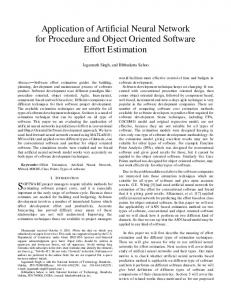
....... , 359◦ . The test data sample, for a particular encoder, thus consists of another data file of 180 values of Rotary Table and the corresponding encoder angle. A representative example of the measured error profiles for 4 encoders is shown in Fig.1. The data presented in this figure uses both the training data file and the test data file. The error at a particular encoder angle ( θEN C ) is evaluated by calculating θEN C - θT AB , where θEN C represents the encoder angle and θT AB is the corresponding angle recorded by the Rotary Table. It is evident from this figure that the error profiles exhibit widely different patterns. Thus having several resolvers of the same tolerance value and from the same batch does not necessarily mean that the individual construction and behavior (i.e error profiles) are also exactly similar on a micro scale. Therefore, one can not use the calibration data of one resolver for compensating the systematic error of another resolver. The mean absolute error (MSE) and RMS error for the 4 encoders are shown in Table 1 below. The minimum and maximum errors of the EN CODER N o. 1 2 3 4
M AE (arc − min) 1.33 0.55 1.09 1.78
RM S (arc − min) 1.48 0.65 1.35 1.31
Table 1: Mean Absolute Error (MAE) and the RMS error for the 4 encoders encoders which are observed to be between ∼-4.42 arc-min ( for Encoder#4) to ∼3.28 arc-min ( for Encoder#3) are quite consistent with the tolerance range of ∼± 6 arc-min quoted by the manufacturer. Artificial Neural Network methodology and training of the network An Artificial Neural Network (ANN) is an interconnected group of artificial neurons that uses a mathematical model for information processing to accomplish a variety of tasks like pattern recognition and classification. The ability of ANN to handle non-linear data interactions, and their robustness in the presence of high noise levels has encouraged their successful use in diverse areas of physics, biology, medicine, agriculture, computer science and astronomy [24,25]. While the theory and the implementation of ANN has been around for more than 50 years, it is only recently that it has found wide spread practical applications. This is primarily due to the advent of high speed, low cost computers that can support the rather computationally intensive requirement of an ANN of any real complexity. In a feed-forward ANN the network is constructed using layers where all nodes in a given layer are connected to all nodes in a subsequent layer. The network requires at least two layers, an input layer and an output layer. In addition, the network can include any number of hidden layers with any number of hidden nodes in each layer. The signal from the input vector propagates through the network layer by layer till the output layer is reached. The output vector represents the predicted output of the ANN and has a node for each 5
(a) Encoder # 1
4
Error ( arcmin )
Error ( arcmin )
4 2 0 -2 -4
(b) Encoder # 2
2 0 -2 -4
0
60
120
180
240
300
360
0
60
180
240
300
360
(d) Encoder # 4
4
Error ( arcmin )
Error ( arcmin )
(c) Encoder # 3
4
120
Encoder angle ( deg)
Encoder angle ( deg)
2 0 -2 -4
2 0 -2 -4
0
60
120
180
240
300
360
0
Encoder angle ( deg)
60
120
180
240
300
360
Encoder angle ( deg)
Figure 1: (a-d) The error profiles ( i.e θEN C - θT AB ) of encoders as a function of the encoder angle (θEN C ). A smoothened spline curve passing through the data points has also been drawn in these figures so that the periodic structure present in the error profiles can be visualized easily. variable that is being predicted. The task of training the ANN is to find the most appropriate set of weights for each connection which minimizes the output error. All weighted-inputs are summed at the neuron node and this summed value is then passed to a transfer (or scaling) function. For a feed-forward network with K input nodes described by the input vector (x1 , x2 ,......), one hidden layer with J nodes and I output nodes, the output Fi is given by the following equation ! K J X X (1) Fi = g wij g wjk xk + θj + θi j=1
k=1
where w ij ,w jk are the weights, θi , θj are the thresholds and g(∗) is the activation function. The training data sample is repeatedly presented to the network in a number of training cycles, and the adjustment of the free parameters (w ij ,, w jk , θi and θj ) is controlled by the learning rate η. The essence of the training process is to iteratively reduce the error between the predicted value and the target value. While the choice of using a particular error function is problem dependent, there is no well defined rule for choosing the most suitable error function. We have used the mean-squared error M SE in this work and it is defined as : P I 1 XX (Dpi − Opi )2 (2) M SE = P I p=1 i=1 where Dpi and Opi are the desired and the observed values and P is number of training patterns. The mean-squared error depicts the accuracy of the neural 6
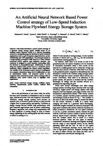
network mapping after a number of training cycles have been implemented. In supervised learning, the correct results (i.e. target values or desired outputs) are known and are given to the neural network during training so that it can adjust its weights to match its outputs to the target values. After training, the neural network is tested by giving it only input values, and seeing how close it comes to reproducing the correct target values. Given the inherent power of ANN to effectively handle the multivariate data fitting, we have studied the feasibility of using it for predicting the error profiles of the encoders. The aim is to determine the correct encoder angle by applying the ANN-predicted error correction to the measured value of the encoder angle. In this work, we have used MATLAB [26] for training and testing various ANN algorithms. MATLAB is a numerical computing environment which allows easy matrix manipulation, plotting of functions and data, implementation of algorithms, creation of user interfaces and interfacing with programs in other languages. The Neural Network Toolbox extends MATLAB with tools for designing, implementing, visualizing and simulating neural networks. The training of the network is performed by presenting 180 values of encoder angles at the one node in the input layer with one node in the output layer representing the corresponding encoder error in arc-min (i.e θEN C - θT AB ). Since it is well known that, one hidden layer is sufficient for approximating well behaved functions [27], we have also used one hidden layer in the present study. The activation function chosen for the present study is the Sigmoid function. Backpropapation algorithm [28] has been by far, the most popular and widely used learning technique for ANN training, we have also used the same algorithm to begin with. With regard to choosing the number of nodes in the hidden layer it is well known that while using too few nodes will starve the network of the resources that it needs to solve a particular problem, choosing too many nodes has the risk of potential overfitting where the network tends to remember the training cases instead of generalizing the patterns. In order to find the optimum number of nodes in the hidden layer for reproducing the error profile of a particular encoder with reasonably good accuracy, we changed the number of nodes in the hidden layer from 10 to 110 (in steps of 10 nodes) and the corresponding MSE was recorded at the end of ANN training for each configuration. The results of this study reveal that while the MSE decreased considerably when the number of nodes in the hidden layer was increased from 20 to 80, increasing the same beyond 80 resulted in only a marginal reduction in the MSE (at the cost of higher computation time). It thus seems that one hidden layer with ∼ 80 nodes is quite optimum for reproducing the error profile of the encoder. Using the same number of nodes in the hidden layer (i.e 80), we then studied the performance of several other error minimization algorithms for identifying the most suitable algorithm which yields the lowest MSE. The algorithms studied were the Resilient backpropagation, Congugate gradient, Fletcher Reeves, Once Step Secant, Levenberg-Marquardt, Scaled conjugate and Quasi Newton [29-31]. Amongst all these algorithms, it was found that Levenberg-Marquardt yields the lowest MSE value of ∼0.0083. Comparative MSE for other algorithms considered by us are given in Table 2 below. Fig.2a depicts the behaviour of the MSE as a function of number of nodes in the hidden layer for the Backpropagation and Levenberg-Marquardt algorithms. The MSE as a function of number of iterations is shown in Fig.2b for these algorithms. An examination of Fig. 2b clearly reveals that the performance of the Levenberg-Marquardt algorithm is 7
ALGORIT HM Res − Backpropagation Conj − Gradient F letcher − Reeves OneStep − Secant Levenberg − M arquardt Scaled − Conjugate Quasi − N ewton
M SE 0.0150 0.0103 0.0144 0.0147 0.0083 0.0096 0.0091
Table 2: Comparative MSE values for all the algorithms considered in this work.
102
102
(a)
(b)
101
Mean Square Error (MSE)
Mean Square Error (MSE)
101
100
10-1 Standard Backpropagation
-2
10
100
10-1 Standard Backpropagation -2
10
Marquardt-Lavenberg
Marquardt-Lavenberg
10-3 0
20
40
60
80
100
120
Number of nodes in hidden layer
10-3 0
1000
2000
3000
4000
5000
6000
Number of iterations
Figure 2: (a) Mean-squared error as a function of number of nodes in the hidden layer. (b) Mean-squared error as a function of number of iterations for 80 nodes in the hidden layer. better than that of the Backpropagation algorithm. It is worth mentioning here that in order to ensure that the network has not become ”over-trained” [32], the ANN training is stopped when the normalised rms error stops decreasing any further (somewhere around 6000 iterations). The MSE for the ANN configuration of 1:80:1 was also checked for the remaining 3 encoders and it was found that it varies from ∼ 0.0098 to ∼0.0165 for the remaining three encoders. A detailed study for determining the optimum number of nodes in the hidden layer in a rigorous manner has also been conducted to make sure that the ANN configuration chosen is not more complex than what is actually warranted. While several empirical results have been reported which provide adhoc, heuristic rules for selecting the number of nodes in a hidden layer, we have followed the Singular Value Decomposition (SVD) approach for finding the optimum number of nodes in the hidden layer by eliminating the redundant nodes [33]. Modification of the ANN structure by analyzing how much each node contributes to
8
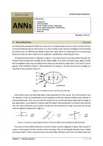
the actual output of the neural network and dropping the nodes which do not significantly affect the output is also referred to as pruning. The basic principle of pruning relies on the fact that if two hidden nodes give the same outputs for every input vector, then the performance of the neural network will not be affected by removing one of the nodes in the hidden layer. In the SVD approach redundant hidden nodes cause singularities in the weight matrix which can be identified through inspection of its singular values. A non-zero number of small singular values indicates redundancy in the initial choice for the number of hidden layer nodes and the approach can be safely used for eliminating these nodes to attain the pruned network model. The weight matrix (denoted by X in the present work) was generated by finding the output of each of the 80 hidden nodes before subjecting them to nonlinear transformation (i.e output of the node before sigmoid function). With a total of 180 training patterns and one hidden layer with 80 nodes, the matrix X thus has 180 rows and 80 columns. The SVD of the matrix X is given by X=U S V T , where U and V are the orthogonal matrices and S is a diagonal matrix with 80 rows and 80 columns. The matrix S contains the singular values of X on its diagonal. Plot of non-zero diagonal elements for all the 4 encoders is shown in Fig.3 and it is 105
105
(a) Encoder # 1
102 101 100 10-1 10
-2
Encoder # 2
103 102 101 100 10-1 10-2 10-3
10-3 0
0
10 20 30 40 50 60 70 Diagonal element number of matrix S
10 20 30 40 50 60 70 Diagonal element number of matrix S
105
105 Diagonal element value
(c) Encoder # 3
104 Diagonal element value
(b)
104
103
Diagonal element value
Diagonal element value
104
103 102 101 100 10-1
(d) Encoder # 4
104 103 102 101 100 10-1 10-2
10-2
10-3
10-3 0
10 20 30 40 50 60 Diagonal element number of matrix S
0
70
10 20 30 40 50 60 70 Diagonal element number of matrix S
Figure 3: (a-d) The singular values of the matrix X as a function of diagonal matrix element number. evident from this figure that number of diagonal elements with non-zero values is