XY stage. To implement error compensation, a neural network error model is .... stage. In this instance, the second axis brings about another source of linear ...
STR/03/036/MECH
Geometrical Error Modelling and Compensation Using Neural Networks S. N. Huang, Y. P. Leow, H. C. Liaw, S. Y. Lim and W. Lin Abstract - This report focuses on a soft error compensation of using neural networks for geometrical error modelling and compensation. Based on different geometrical error components, the report describes the methodology of deriving the neural network error models for three different types of machine, mainly a single axis stage, a dual parallel axes stage, and a full XY stage. To implement error compensation, a neural network error model is generally incorporated into the motion control scheme. The actual realizations of the geometric error compensation for the three stages as well as the results after the error compensation are detailed in the report.
look-up table. The look-up table is built based on points collected and calibrated in the operational working space of the machine. However, there are several disadvantages associated with the look-up table which become clearly significant with increasing precision requirements. First, the look-up table has extensive memory requirements. When the number of data points calibrated in a 3D workspace increases by a factor of N, the number of table entries in3
creases by the order of N . This difficulty is thus especially significant for high precision machines, where a huge amount of calibration effort is necessary in order to compensate errors to within an acceptably precise threshold. Secondly, for the look-up table, the errors associated with intermediate points of the recorded data are compensated by using linear interpolation. This assumes the error to vary linearly between the calibrated points, and neighbouring points are not utilised to improve the interpolation. Linear interpolation may suffice if the calibration is done at very fine intervals compared to the precision requirements. However, this will in turn imply tremendous memory requirements which may be beyond the capacity of a typical look-up table. Thirdly, the look-up table does not have a structure which is amenable to direct expansion when considering other factors affecting positioning accuracy, such as thermal and other environmental effects.
Keywords: High precision, Motion control, Neural networks, Geometric error compensation 1
BACKGROUND
Compensation for geometrical errors in machines has been applied to Co-ordinate Measuring Machines (CMMs) and machine tools to minimise the relative position errors between the end-effector of the machine and the workpiece [1-5]. Given an adequate machine design, a large proportion of these errors are geometrical errors which are completely repeatable and reproducible, and therefore amenable to modelling and compensation. While widespread incorporation of error compensation in machine tools has remained to be seen, the application in CMMs is tremendous and today, it is difficult to find a CMM manufacturer who does not use error compensation in one form or another [1]. The development in error compensation is welldocumented by Evans [2]. Early compensation methods mainly utilized mechanical correctors, in the form of leadscrew correctors, cams, reference straightedges etc. Compensation via mechanical correction, however, inevitably increases the complexity of the physical machine. Furthermore, mechanical corrections rapidly cease to be effective due to mechanical wear and tear. The corrective components have to be serviced or replaced on a regular basis, all of which contribute to higher machine downtime and costs.
Using neural networks (NNs) is an alternative approach to the compensation of geometrical errors. The advantages of NNs for practical error compensation applications lies in the following properties: 1) NNs could be used to approximate any continuous mapping, 2) NNs achieve the approximation through learning, 3) parallel processing and nonlinear interpolation can be easily accomplished with NNs. 2
OBJECTIVE
This report focuses on the soft compensation approach of using the NNs for modelling of geometrical errors. Based on different geometrical error components, three NNs error models are derived for a single axis stage, a gantry (dual parallel axes stage) and a full XY stage. To implement the error compensation, a NNs error model is incorporated as part of the motion
Traditionally, the geometrical errors to be compensated are commonly stored in the form of a
1
Geometrical Error Modelling and Compensation Using Neural Networks
errors. Positioning errors can also arise as a result of the machine axes inheriting out-ofsquareness errors. Squareness is the 90-degree orientation of one axis relative to another axis. A deviation from this right angle is referred to as the out-of squareness for the axes. Linear motion alone along the X-direction (without considering the rotational, straightness and squareness issues) may also inherit positioning errors due to encoder errors.
control scheme. The report describes in detail the methodology as well as the actual realization for the stages. 3
METHODOLOGY
3.1
Geometrical error calibration
The accuracy and precision of a positioning machine is determined, in large proportions, by the geometrical properties of the machine. For a machine with a 3-dimensional (3D) cartesian workzone, there are six degrees of freedom associated with • • •
Therefore, for a 3D cartesian machine, a complete calibration of the geometrical error should include measurement of the six degrees of freedom for each of the three axes, and the squareness between X, Y and Z. A total of 21 sources of error needs to be calibrated.
linear motion rotational motion (pitch, yaw, roll) side to side, and up and down motion (straightness)
3.2
Geometrical error model
The basis of all soft compensation approaches is a geometrical error model which relates the positioning error to the measured position of a focused point. In this section, we will derive these relations for commonly encountered configurations of positioning stages.
The six degrees of freedom in motion ultimately give rise to the geometrical errors associated with the machine.
3.2.1
Single axis stage
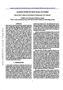
For this simple stage, we are only keen in the linear motion along one axis and the linear error resulting along this axis arising, for example, due to inherent encoder calibration errors. Consider the single axis stage as shown in Fig. 2, moving along the X direction. When the focused point (P) translates from the origin O to a nominal distance OP, it follows that
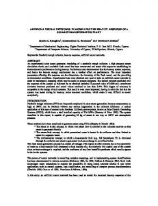
Fig. 1. Inaccurate positioning.
To illustrate, consider a workpiece on a table which possesses positioning or geometry inaccuracies (Fig. 1). The workpiece is to be machined by a fixed tool above the table. Even when the table is commanded to move only along the X direction, its other degrees of freedom arising from a less than perfect mechanical design or assembly process will incur a positioning error, and therefore a workpiece which is not machined to desired parameters. Undesirable angular motion of the table (in pitch, yaw and roll) as it translates along the X direction contributes to the final positioning error. Roll refers to the rotation about the axis of motion while pitch and yaw refer to the rotations about the axes perpendicular to the axis of motion. Nonstraightness of travel is another source contributing to the positioning errors. Non-straightness can refer to side-to-side, and up and down motion perpendicular to the desired direction of movement. If the table is commanded to move along the X direction, unwanted motion in the Y and Z directions are termed the straightness
OP=x+δ(x),
(1)
where x is the desired position and δ(x) represents the linear error along x axis. The geometrical error along the x is therefore given by
∆x=δ(x),
(2)
Fig. 2. Single axis stage.
3.2.2
Dual axis (gantry) stage
In some installations, one axis is controlled by two drives and two feedback systems, for ex-
2
Geometrical Error Modelling and Compensation Using Neural Networks
assumed that, initially, all three origins coincide and the axes of all three systems are aligned. Thus, when the bridge moves a nominal distance Y, the actual position of the bridge origin O1, with respect to the table system, is given by the vector:
ample, the Spar Mill machine and H-type gantry stage. In this instance, the second axis brings about another source of linear displacement error. It is necessary to do calibration for this additional error source. Consider a dual axis stage as shown in Fig. 3, moving a focus point along an axis which is still X in this example. The focus point moves from the origin O1 to O1P, while the other axis moves from the origin O2 to O2P. It follows that
O1P=O1P1+P1P for x1-axis
δ x ( y) OO1 = y + δ y ( y )
At the same time, the bridge coordinate system rotates with respect to the table system due to the angular error motion. This rotation can be expressed by the matrix:
(3)
and
O2P=O2P2+P2P for x2-axis
(4)
1 R1 = − ε y
Thus, we have
O1P=x+δ(x1)+δ(x1,x2) for x1-axis
(5)
O2P=x+δ(x2)+δ(x1,x2) for x2-axis
(6)
εy 1
(8)
Similarly, when the X carriage moves a nominal distance X, we have
x + δ x ( x) 1 O1O2 = , R2 = − ε x δ y ( x) − αx
where δ(x1), δ(x2) are the linear errors of x1 and x2 axes, respectively, and δ(x1,x2) refers to the cross-coupled linear error arising after each individual axis error is calibrated. A two-phase calibration process may thus be used for such a dual-axis stage. During Phase 1, the individual error along either axis (δ(x1), δ(x2)) is first calibrated. Then the axes are individually compensated. After compensation of the individual axis, Phase 2 of calibration will seek to derive the cross-coupled linear error δ(x1,x2) and subsequently compensate for it.
xp O2 P = , yp
εx 1
,
(9)
(10)
where x, y are the nominal positions; xp, yp represent the offsets of the tool tip (Abbe error); δu(v) is the translational error along the udirection under motion in the v direction; εu refers to the rotation along the u axis; and α represents the out-of-squareness error. Therefore, a volumetric error model can be derived with respect to the table system:
OP=OO1+R1-1O1O2+R1-1R2-1O2P
(11)
Substituting (7)-(10) into (11) and noting that εuεv≈0,εuδu(v)≈0,εuα≈0 since εu,δu(v),α are very small, the geometrical error compensation along the x and y directions are respectively:
Fig. 3. Dual axis stage.
3.2.3
(7)
General XY stage
A general XY stage with three independent plane systems is as shown in Fig. 4. The plane systems are associated respectively with the table (0,X,Y), the bridge (01,X1,Y1), and the carriage (02,X2,Y2). For conceptual purposes, the measurement systems for the bridge and carriage are shown in Fig. 4 as being attached to the bridge and X carriage respectively, via small, non-existent connecting rods. It will be
∆ x=δx(x)+δx(y)- yp(εx+εy)+xp,
(12)
∆ y=δy(x)+δy(y)+xεy-xα+xp(εy+εx)+yp.
(13)
This is a 2D error model. For a more general 3D error model, readers can review the literature [2] for a detailed presentation. It should be noted that the error sources are all calibrated using only appropriate combinations of linear displacement measurements.
3
Geometrical Error Modelling and Compensation Using Neural Networks
where O
N
1 j
=
∑
W
ij
X
i
and Xi is the input
i=1
(or input sample) of the NN. 2. Compute the output of OUTPUT layer,
X 21 = Fig. 4. XY stage.
1 1 + exp(−O21 − θ 21 )
where X21 is the output of the NN, and N1
3.3
O21=
Error compensation schemes
3. Update the weights from HIDDEN to OUTPUT layer, W1j1 according to
W1tj+11 = W1tj1 + η1δ 11 X 1 j where
j =1
i =1
gain
factor,
and
d X21
with being the desired output (or output sample), and X21 being the NN output. 4. Update the weights from INPUT to HIDDEN layer, Wij
X 2 k = f ( X ; W ) = σ [ ∑ W1 jk σ [ ∑ W ij xi + θ 1 j ] + θ 2 k ]
Wijt +1 = Wijt + η 2δ j X i
with σ (⋅) being the activation function, Wij the first-to-second layer interconnection weights, and W1jk the second-to-third layer interconnection weights. θ 1j, θ 2k, are threshold offsets. It is desirable to adapt the weights and thresholds of the NN off-line to achieve the required approximation performance of the net. That is, the NN should exhibit a “learning behavior''.
where
δ
j=[
δ
η2 > 0
is
gain
factor,
and
11W 1j1]X1j(1-X1j).
5. Update the thresholds,
θ 21, θ 1j
θ 21t +1 = θ 21t + η1θ δ 11 , θ 1t j+1 = θ 1t j + η 2θ δ j
In this report, the NN is designed as a multiinput and single-output (MISO) function. The input with weightings is connected to a neuron node. The sigma function is used. The gradient algorithm based on the backpropagation error for the NN is summarized as follows:
where
η1θ
and
η2θ >0 are gain factors.
A terminating condition for the training process is usually formulated, that is
1. Compute the output of the HIDDEN layer, X1j
X1j =
is
δ 11 = ( X − X 21 ) X 21 (1 − X 21 )
One of the well-developed NNs is a three-layer N perceptron NN. Given X ∈ R , a three-layer NN has a net output given by N
η1 > 0 d 21
Neural networks
N1
W1j1X1j.
j =1
Soft compensation techniques will require that the error descriptions are stored in the computer memory. To reduce the number of points where errors must be measured, it is necessary to have a mathematical mapping to model the error behavior. For that purpose, NNs are employed. The main property of a NN used here for estimation purposes is the function approximation property [6]. 3.3.1
∑
ε=
1 1 + exp(−O1 j − θ 1 j )
1 M l ( X 21dl − X 21 )2 ∑ 2 l =1
where l represents the sample number. The iterative weights tuning process is terminated when the error converge within a specified threshold. Thus, the optimum weights W can be
4
Geometrical Error Modelling and Compensation Using Neural Networks
at a larger node number. For a real-time control system, a larger NN node number will increase the difficulty to implement the NN control. Thus, for NN learning, it is important to strike a tradeoff between the. accuracy and NN structure.
obtained. The training is usually a trade off in terms of the quality of fit and the iteration time 4
RESULTS
A NN model describing the linear error is thus obtained
In this section, the experimental results are given to illustrate the proposed method. We define that the unit of the vertical axis is µm , while the unit of the horizontal axis is mm. 4.1
δ(x)=f(x;W*),
(14)
where x is the nominal distance, f(.) is the NN, * and W is a set of the optimal weights of the trained NN. The trained NN written in C is embedded into the control loop as shown in Fig. 8. The compensation result is shown in Fig. 9. The accuracy is now compressed to about 3.5 µm.
Single axis stage
Fig. 5 shows the experimental setup of the single axis stage. For the purpose of modeling of the linear errors, the NN is trained using 41 samples which are averaged values from four cycles of bi-directional runs. The number of input and output nodes for the network are both fixed at one (corresponding to the number of input and output variables). The following MATLAB NN program is used to generate the NN structure.
Fig. 6. NN training under terminating condition object_error