WSEAS TRANSACTIONS on INFORMATION SCIENCE and APPLICATIONS
Leonardo Ivirma, Mary Vergara, Sebastian Provenzano, Francklin Rivas, Anna Perez, Francisco Fuenmayor
Artificial Neural Networks application for Stress Smoothing in Hexaedrons LEONARDO IVIRMA*, MARY VERGARA**, SEBASTIAN PROVENZANO***, FRANCKLIN RIVAS^, ANNA PEREZ§, FRANCISCO FUENMAYOR¤ Universidad de Los Andes * Dpto. de Investigación de Operaciones **, ***Grupo de Diseño y Modelado de Máquinas, Escuela de Ing. Mecánica ^ Laboratorio de Sistemas Inteligentes § Facultad de Ciencias Económicas y Sociales, Escuela de Estadística VENEZUELA
[email protected],
[email protected] ¤ Universidad Politécnica de Valencia, ESPAÑA Abstract: In this paper it is presented the use of artificial neural networks to improve the tension fields obtained from the finite element discretization method. It was significantly reduced the time needed to reach solutions, with accuracy similar to the areas smoothing tensions methods: Superconvergent Patch Recovered (SPR) and Recovery by Equilibrium Patches (REP) improved. It is solved two cases that show the comparative advantages in terms of time spent by the neural network and the techniques described above for making improvements in the original solution: Artificial Neural Networks used only 7% and 70% respectively of the original time spent by the smoothing technique in such cases. As bigger is the magnitude of the problem, the greater the difference in the time required for the solutions, being better the neural network. Data used for this study come from cases of different features: with a smooth solution, a thick wall sphere exposed to inner pressure and one with singularities, a plate loaded with a lateral crack. Key-Words: Superconvergent Patch Recovery, Stress Smoothing, Artificial Neural Networks. REP and SPR improved techniques are presented in Vergara [5]. The advantages of conducting some improvements in the originals methods of smoothing processes, as well as a series of tests and comparisons between the developed SPR-R and REP-R techniques, have been the subject of studies in Vergara et al. [6], whereas in Vergara et al [7] it is presented a study of the combination of these techniques. The problem is that, in general, the techniques that give good results are complex and computationally expensive when the number of elements grows by the refinements of adaptive application, so for the analysis of complex three-dimensional geometries, the execution time becomes even "prohibitive", especially considering that it may be a considerably large volume of data. These techniques provide very good results in terms of accuracy, but the time required for obtaining them requires the search for new alternatives. For making the process of smoothing tensions, this paper uses Artificial Intelligence, and in particular the Artificial Neural Networks (ANN), which have demonstrated effectiveness in problems with very diverse nature, as can be seen in Moreno article [8] and in some jobs such as those of Möller [9] can be
1 Introduction Considering that in most of the real problems is not possible to calculate analytical solutions, the finite element method (FEM) is a good alternative for obtaining approximate tension fields. However, engineers, in its continuing search for better solutions, have managed to improve the calculation of continuing tensions, beyond making a simple averaging in nodes tensions, considering techniques for smoothing areas of tension, among others. This technique was initially proposed by Zienkiewicz and Zhu [1] and is known as SPR, after several improvements have been made on it for twodimensional finite elements. Another most recent technique proposal by Boroomand and Zienkiewicz [2] [3], suggest a procedure known as REP to build smooth tensions arising from the finite element solution, which requires the fulfillment of balance in the patch and does not require previous knowledge concerning superconvergence points. One application of the SPR improved technique (SPR-R) in twodimensional elements can be found in Ródenas [4] where in its implementation it is ensured the exact compliance of the restrictions imposed on nodes in the contour, while hexahedrons implementation of the
ISSN: 1790-0832
872
Issue 5, Volume 6, May 2009
WSEAS TRANSACTIONS on INFORMATION SCIENCE and APPLICATIONS
Leonardo Ivirma, Mary Vergara, Sebastian Provenzano, Francklin Rivas, Anna Perez, Francisco Fuenmayor
bring stress from PTG, and similarly Up to eight. As each case has different attributes including the number of data that are going to be used for calculations, it will be used an ANN model for each case. It was used MatLab software [12] and it’s Neural Network Toolbox [13] for the development of ANN models [14, 15], which are considered multilayer, feedforward, with supervised training algorithms. Supervised neural networks require a number of patterns composed of input variables and desired outputs. Entries from the FEM in the PTG for the entire mesh are obtained from a commercial finite element computer program. Desired outputs are obtained from the implantation in MatLab of the smoothing tensions process with the SPR-R and REPR techniques.
seen the use of neural networks in the finite element area and Mahadevan [10] and Wang [11] have used other of the artificial intelligence techniques such as fuzzy logic. In this paper we evaluate the potential of ANN, for obtaining improved tension stress (σ *) from those obtained by FEM, generating a novel alternative that provides accurate and faster solutions than the methods used so far for three-dimensional problems. This evaluation includes a comparison of the neural networks predictions models with the original solutions from the FEM and also the smoothing techniques of proven accurate: SPR-R and REP-R.
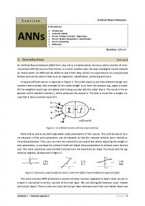
2 Experiments development and the Improved Tensions Calculation models For evaluating the ANN, it was used data from the numerical solution of finite element at the gauss points (PTG) of linear hexahedrons with complete integration for two static problems: Thick wall sphere exposed to inner pressure (see Figure 1a) with: internal radio (R1), outer radius (R2), inner pressure (P). Plate loaded with lateral crack, Figure 1b shows the location of each of the variables (a, b, c, d and σ).
Figure 1- a.Sphere exposed to inner pressure, b. Plate with lateral crack
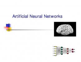
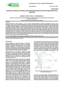
2.1 Definition and analysis of the problem The problem has been defined as the calculation of a set of tensions in the nodes. There are stresses initially calculated at the PTG, which are data entry, being obtained from the solution by the FEM. The threedimensional stress field is a vector which has six components: three of normal stress in x, y, z directions (σx σy σz) and three shear stress at the xy, xz, yz (σxy σxz σyz). Figure 2 shows an assembly node, where it is wanted to know the value of stress and hexahedrons division that defines the mesh of the original geometry. Each element shared by the node provides an array of stress for calculating the continuous stress. Stress in the PTG vary in a single element, so depending on the node is taken either of those stress. Considering the results of Vergara et al [7], there are obtained the smoothed stress fields of SPR-R and REP-R techniques using a strategy of refinement by subdivision. The calculation of stress field in a node depends on the number of different elements that are shared, so for the configurations studied there are eight different cases for calculating tensions in a node. If the node is shared by only a distinct element, then that element provides the tension in the PTG for the calculation of its smoothed tensional field; if the node is shared by two elements (see Figure 3), then both
ISSN: 1790-0832
The main idea is to train the ANN with data obtained from the initial solutions of these two techniques for smoothing tensions, with the idea that ANN will learn the pattern embedded in each one. Then, using data that were not known by the network during its training, it is evaluated the predictive ability of this model for obtaining the improved tensional fields and is compared both in accuracy and in time necessary for obtaining the solution with those obtained by SPR and REP-improved.
Figure 2- Assembly node in hexahedrons elements
873
Issue 5, Volume 6, May 2009
WSEAS TRANSACTIONS on INFORMATION SCIENCE and APPLICATIONS
Leonardo Ivirma, Mary Vergara, Sebastian Provenzano, Francklin Rivas, Anna Perez, Francisco Fuenmayor
never seen by the network during training (Sd = 5), with a lot of elements. It is compared the obtained models from the testing case 3 with the testing case 5. Testing case 8 (TC8). It is considered the sphere of the case 1, but this time with a subdivision phase that was never seen by the network during training (Sd = 4), with a lot of elements. It is compared the obtained models from the testing case 1 with the testing case 5. Table 1. Number of nodes in the considered cases Type of nodes (shared nodes) Test \Node ONE TWO THREE FOUR SIX EIGHT 36 1 577 36 3 500 619 3 500 TC1 36 2 702 36 3 500 702 3 500 TC2 0 3 500 242 4 000 96 3 366 TC3 96 3 086 0 3 500 310 3 500 TC4 32 7 304 242 8 295 TC5 112 1 914 32 8 152 344 9 360 TC6 112 2 144
Figure 3- Patterns for shared nodes
2.2 Considered Testing Cases For the sphere and plate with crack, there are solutions at various stages of subdivision, variation in load and geometry. 8 cases have been designed to test (with 8 models based on the number of shares), which are detailed on number of nodes in Table 1 and are described as: Testing Case 1 (TC1). There are considered stress data in thick wall spheres exposed to inner pressure, with SPR- improved smoothing technique, pressure changes and the stage of subdivision (Sd). Data: R1 = 5 m, R2 = 20 m, E = 1000 N / m 2 , ν = 0.3, P = 1 2 N / m 2 , Sd = 0, 1, 2, 3 and P = 0.5 N / m . Testing Case 2 (TC2). Like case 1, but with REPimproved smoothing technique. Testing Case 3 (TC3). There are considered tensions data in plates loaded with stress and lateral crack with SPR-improved smoothing technique, with variations in load and stage of subdivision. Data: a = 0.6 m, b = 2 m, c = 6 m, E = 107 N / m 2 , ν = 0.333 (adimensional), σ = 1000 N / m 2 : Sd = 0, 1, 2, 3, 4, σ = 2000 N / m 2 . Testing Case 4 (TC4). Like case 3, but with REPimproved smoothing technique. Testing Case 5 (TC5). There are considered changes in loads, geometry and subdivision phase with the SPRimproved smoothing technique. Data: Combination of testing cases 1 and 3. Testing Case 6 (TC6). There are considered changes in loads, geometry and subdivision phase with the REPimproved smoothing technique. Data: Combination of testing cases 2 and 4. Testing Case 7 (TC7). It is considered the crack of case 3, but this time with a subdivision phase that was
ISSN: 1790-0832
3 Design of the Artificial Neural Networks The selection of models is handle according to the possibility of variation of parameters of the ANN, such as: The number of hidden layers, the number of neurons in each layer, type of activation functions and learning algorithm. The ANN architecture is denoted by brackets ([]), starting with the number of neurons in the input layer and ending with the output layer and sequentially for the hidden layers. To reduce the space of possibilities, initially, there were done pilot tests for reducing the number of parameters to vary. It was proved a wide range of training algorithms, but the Levenberg-Marquardt and the Broyden-FletcherGoldfarb-Shann were significantly more efficient than others. For the choice of models, only two were considered, and also it was added the default one used by MatLab (backpropagation by the gradient descent, momentum and adaptive learning rate). In terms of the number of hidden layers, it has been demonstrated in [16] that a single layer network is usually enough for approximating almost any type of nonlinear function, but it has also been experimented with some architectures of two hidden layers for searching better results. It was chosen linear activation function for neurons of the output layer, since the outputs are not bounded and may take positive and negative values. For the hidden layers it was used the hyperbolic tangent function. Once it is defined the combination of parameters that provide the better performance, in each case it is evaluated if that answer is satisfactory compared with the desired one; for this a graphic proof is made with the predicted and desired values
874
Issue 5, Volume 6, May 2009
WSEAS TRANSACTIONS on INFORMATION SCIENCE and APPLICATIONS
Leonardo Ivirma, Mary Vergara, Sebastian Provenzano, Francklin Rivas, Anna Perez, Francisco Fuenmayor
building a simple linear regression model for comparing the outputs of the ANN and those provided by smoothing techniques. After showing that ANN can learn the relationship between the initial tensions in the PTG and the smoothed ones it is made the final test, which is comparing directly the ANN with a problematic case for the classical smoothing techniques and evaluate how good the results with the novel technique are. This will use the models obtained and evaluated in the test cases 7 and 8.
4.1 Best Architecture for Testing cases A summary for ANN model parameters election is presented in Table 3, where can be seen different configurations and their performance measures. Not only for the first Testing Case, but for the other and in each type of nodes, the "trainlm" learning algorithm showed a significantly better performance than the "traingdx" and "trainbfg” methods. The above process is conducted in similar way for the rest of the cases for defining the best architecture. In Table 3 it is presented a summary of them.
3.1 Using the ANN model One of the ANN advantages is that once trained does not need more smoothed stress fields values, so it is overcame the execution time problem and computing cost associated with solutions that have been obtained using the SPR and REP improved techniques. The process for obtaining them and their evaluation when is better the use of ANN instead of the classic techniques, is shown in Figure 4.
Table 3. Best Architecture for all cases and considered parameters Test \Node TC2
1 [6-3-6]
2 [12-10-106]
3 [18-76]
[6-6-6]
[12-25-6]
-
[6-8-3-6]
[12-30-6]
-
TC3 TC4
TC5 [6-3-8-6] TC6 [6-20-6]
[18[12-12-3-6] 12-6] [12-10-10- [18-36] 12-6]
4 [2420-6] [24-66-6] [24-96] [241010-6] [24-86]
6 [3615-6] [369-6] [3630-6]
8 [48-206] [48-126] [48-106]
[366-6] [3615-6]
[48-8-36] [48-5-6]
4.2 Performance Measures and Graphics Tests According to the characteristics considered in Table 4 it is presented for each case the measures of performance and graphic evidence for the best configurations of ANN obtained. The idea is to compare the values obtained with the ANN, compared to the FEM and the smoothing methods described above. The data are divided into three groups: training, validation 1 and validation 2. The validation group 1, is used for evaluating the ANN once trained, but also during the iterations of the training it is calculated the validation error of this group, stopping the process if the error over several cycles is increased, ie attempts to stop the algorithm at the appropriate number of cycles, avoiding overtraining. The validation group 2 is used when there are insufficient data to further validate the model. The idea is that instead of training the ANN with too much data, it is preferable having more information concerning the quality of the prediction for the data unknownby the ANN, which is accomplished by creating a second set of validation.
Figure 4- Obtaining Improved Stress with ANN The training error (E. Train) and testing error (E. test) while lower, the better, while the correlation coefficient while the nearest to one is best fitted by the adjustment. Both measures are used together for selection. Time for building the models (t_seg) and the number of cycles (cycles), are important parameters to observe, and therefore are also evaluated, see table 2. Table 2. ANN model parameters Selection for the other type of nodes Type Node
cycles
E. test.
Correl.
1
49
2
0,0001
0,000100
0,9995
2
55
100
0,00013
0,000360
0,9959
3
107
51
0,000000 0,000002
0,9999
4
20
184
0,00005
0,000100
0,9991
6
101
336
0,000001 0,000002
0,9996
8
125
772
0,00000
0,9999
ISSN: 1790-0832
t(seg) E. Train.
0,000003
875
Issue 5, Volume 6, May 2009
WSEAS TRANSACTIONS on INFORMATION SCIENCE and APPLICATIONS
Leonardo Ivirma, Mary Vergara, Sebastian Provenzano, Francklin Rivas, Anna Perez, Francisco Fuenmayor
The less progress with respect to the initial solution is for the group TWO. However, the improvement is considerable, as is corroborated in Figure 5, which shows predictions and progress as regards the initial solution. The settings of the regression model between predicted and desired values form a straight line with a slope which passes through the origin. The greatest progress was seen in group THREE (Figure 6), which has an adjustment of 0.99.
Table 4. Considered Characteristics Description
(C) t1(seg) (D) CCRNA1 (E) CCMEF1 (F) ECMRNA1 (G) ECMMEF1
Number of patterns used for training Number of patterns used for validation and that the network used for avoiding overtraining Time spent by the network for the prediction of the first validation group. Correlation coefficient between the outputs produced by the model and the desired ones, for the first validation group. Correlation coefficient between the outputs initially obtained by the FEM and the desired ones, for the first group validation. Mean square error for the outputs produced by the model and the desired ones, for the first group validation Mean square error between the outputs initially obtained by the FEM and the desired ones, for the first group validation.
Stress field in Y
Stress field
(A) NPE (B) NPV1
Testing Case 1 (TC1) Table 5 shows the performance of the ANN for the types of nodes present. For type TWO, FOUR and EIGHT are insufficient data for constructing two validation sets. Both results are similar. In all cases leads to a significant improvement on the initial FEM solution and results are very similar to the technique SPR-improved. The time for predicting the largest number of nodes, in this case 1500, is 2 seconds.
S. Field FEM S. Field ANN S. Field Smoothed S. Field Theoric
Nodes
Figure 5- Variable Y of case TWO. Stress field in X S. Field FEM S. Field ANN S. Field Smoothed S. Theory
Table 5. Performance Summary for the ANN in TC1
ONE
TWO
THREE
FOUR
SIX
EIGHT
NPE
29
830
29
1 700
526
1 700
NPV
7
183
7
300
93
300
t(seg) CCRNA CCMEF ECMRNA ECMMEF
1
1
1
1
1
1
0.997
0.995
0.9999
0.9989
0.9996
0.9997
0.970
0.948
0.9972
0.9738
0.9929
0.9967
0.0008 0.0004 0.000002
0.00009
0.000003 0.00001
0.0188 0.0060 0.000127
0.00335
0.000047 0.00011
Stress field
Group 1 Measure \Node
Node s
Group 2 -
NPV t(seg) CCRNA CCMEF ECMRNA ECMMEF
664
-
1
1 500
-
2
1 500 2
-
0.996
-
0.9993
-
0.9997
-
0.980
-
0.9821
-
0.9982
-
0.0001
-
0.00005
-
0.00001
-
0.0010
-
0.00212
-
0.00007
ISSN: 1790-0832
F
igure 6. Variable X of case THREE.
Testing Case 2 (TC2) Table 6 shows the performance of each type of nodes in this test case. For type TWO, FOUR, SIX and EIGHT are insufficient data for constructing two validation sets, the results remain similar for both.
876
Issue 5, Volume 6, May 2009
WSEAS TRANSACTIONS on INFORMATION SCIENCE and APPLICATIONS
Leonardo Ivirma, Mary Vergara, Sebastian Provenzano, Francklin Rivas, Anna Perez, Francisco Fuenmayor
Stress Stress field field in in X X
S. Field FEM S. Field ANN S. Field Smoothed S. Theory
Table 6. Performance Summary for the ANN in TC2
TWO
THREE
FOUR
SIX
EIGHT
NPE
29
1 814
29
1 700
307
1 700
NPV
7
186
7
300
77
300
t_1 (seg) CCRNA CCMEF ECMRNA ECMMEF
1
1
1
1
1
1
0.92
0.993
0.9986
0.9993
0.9991
0.9997
0.82
0.930
0.9257
0.9760
0.9927
0.9978
Stress field
Group 1 Measure \Node ONE
Nodes
Figure 8. Variable X of case SIX 0.018 0.0006
0.0003
0.0001
0.000008 0.000006
0.040 0.0072
0.0239
0.0025
0.000087 0.000065
Testing Case 3 (TC3) Table 7 shows the behavior of this testing case. For nodes of type TWO, FOUR and EIGHT it can be constructed two validation sets, due to insufficient data. As expected, the results in both groups were similar. Again, for all node types are considerably improve the solutions obtained by FEM and the results are very similar to the technique SPRimproved. Times are very good, because the most time used for a group of data is 1700 nodes is 3 seconds. The result that seems a solution which least approximates the smoothing technique is presented for the nodes in TWO, but as is shown in Figure 9, is better than the FEM solution. In Figure 10 for SIX types of nodes can be noted the high accuracy achieved.
Group 2 NPV
-
702
-
1 500
318
1 500
t_2 (seg) CCRNA CCMEF ECMRNA ECMMEF
-
1
-
3
1
3
-
0.995
-
0.9993
0.9997
0.9999
-
0.973
-
0.9817
0.9982
0.9921
-
0.0002
-
0.0001
0.000001 0.000004
-
0.0012
-
0.0021
0.000010 0.000032
As in the TC1 for all types of node is achieved significant improvement over the solutions of FEM and the results are very similar to the REP-improved smoothing technique. Times required are excellent, and for predicting the largest number of nodes (1500) it takes just 3 seconds. The result where improvement is less is for the group ONE, but as it can be seen in the testing graph shown in Figure 7, is significantly better than the FEM solution. The greatest progress was seen in group SIX, which is also evidenced in the test graph of Figure 8
Table 7. Performance Summary for the ANN in TC3 Group 1 Measure \Node
Stress field in YZ S. Field FEM S. Field ANN S. Field Smoothed S. Theory
ONE
TWO
FOUR
SIX
EIGHT
NPE
77
1.700
1.700
206
1.700
NPV
19
300
300
36
300
t_1 (seg) CCRNA CCMEF ECMRNA ECMMEF
1
1
1
1
1
0,9992
0,9976
0,9956
0,99997
0,9994
0,9658
0,9853
0,9494
0,99945
0,9959
683,4
13.994,1
17.741,2
70,6
2.450,7
29.561,4 234.293,0
321.704,3
1.283,6
17.058,3
Stress field
Group 2
Node s
Figure 7. Variable YZ of case ONE.
ISSN: 1790-0832
877
NPV
-
1.366
1.500
-
2.000
t_2 (seg) CCRNA CCMEF ECMRNA ECMMEF
-
3
3
-
3
-
0,9936
0,9889
-
0,9987
-
0,9786
0,9383
-
0,9921
-
44.138,1
34.510,1
-
40.855,8
-
384.362,4
229.860,1
-
28.131,8
Issue 5, Volume 6, May 2009
WSEAS TRANSACTIONS on INFORMATION SCIENCE and APPLICATIONS
Leonardo Ivirma, Mary Vergara, Sebastian Provenzano, Francklin Rivas, Anna Perez, Francisco Fuenmayor
Table 8. Performance Summary for the ANN in TC4 Stress field in X
Group 1
S. Field FEM S. Field ANN S. Field Smoothed
Stress field
Measure \Node
ONE
TWO
FOUR
SIX
EIGHT
NPE
77
1.600
1.700
264
1.700
NPV
19
400
300
46
300
t_1 (seg) CCRNA CCMEF ECMRNA ECMMEF
1
1
1
1
1
0,99999
0,9925
0,9956
0,9999
0,9987
0,99841
0,9517
0,9543
0,9990
0,9974
5,8
27.082,1
17.879,5
204,7
3.723,1
1.741,1 427.276,0
208.901,3
2.785,2
7.278,0
-
1.500
Group 2 -
NPV Nodes
t_2 (seg) CCRNA CCMEF ECMRNA ECMMEF
Figure 9- Variable X of case TWO
Stress field in X S. Field FEM S. Field ANN S. Field Smoothed
1.086
1.500
2
3
-
0,9479
0,9821
-
0,9963
-
0,9332
0,9495
-
0,9952
-
249.979,5
58.329,7
-
14.052,2
-
953.536,3
197.479,6
-
12.830,7
3
Stress field in Y
Stress field
Stress field
S. Field FEM S. Field ANN S. Field Smoothed
Node s
Figure 10. Variable X of case SIX Testing Case 4 (TC4) In table 8 it is shown the performance of the different nodes in TC4. Nodes for TWO, FOUR and EIGHT are used the two groups for validating, where both groups had similar results. Again, all the node types significantly improved the finite element method solutions, which are also very similar to the REPimproved technique. Regarding the time needed to obtain the solution, the maximum value used is 3 seconds for 1500 nodes. According to data tabulated for the nodes type EIGHT, is not improved much the initial solution, but as shown in Figure 11 the progress is remarkable, with good regression fit. Nodes for the prediction of type ONE has the highest degree of precision, and this is evidenced in Figure 12.
ISSN: 1790-0832
Nodes
Figure 11. Variable Y of case EIGHT
Stress field
Stress field in Z
S. Field FEM S. Field ANN S. Field Smoothed
Node s
Figure 12. Variable Z of case ONE
878
Issue 5, Volume 6, May 2009
WSEAS TRANSACTIONS on INFORMATION SCIENCE and APPLICATIONS
Leonardo Ivirma, Mary Vergara, Sebastian Provenzano, Francklin Rivas, Anna Perez, Francisco Fuenmayor
Testing Case 5 (TC5) In this testing case, it is combined the sphere and cracking data, the results are shown in Table 9, showing that for nodes TWO, FOUR and EIGHT there are used the two validation groups because of the amount of available data. The ANN model is an improvement over the FEM solution, although this varies according to the type of node, like the precision degree regarding the SPR-improved technique. These differences can be noted when comparing figures 13 and 14, the first is the type of nodes with less precision (TWO) and the second is largest (THREE). Furthermore, the prediction of more than 6000 nodes is done in 8 seconds.
Stress field
Stress field in XZ
Nodes
Figure 14. Variable XZ of case THREE Testing Case 6 (TC6) In this testing case, again it is combined data from sphere and cracks for the REP-improved technique, the results can be seen in the table 10, where there are two validation groups for nodes of type TWO, FOUR and EIGHT. The results are very similar to the previous case, having less accurately fitness for nodes TWO and FOUR, and more for the rest. However, as noted in Figures 15 and 16, despite having differences in the quality of the prediction, in both cases the results are successful. The execution time is still interesting because 7 seconds is used to predict more than 7000 nodes.
Table 9. Performance Summary for the ANN in TC5 Grupo 1 Measure \Node
ONE
TWO
THREE
FOUR
SIX
EIGHT
NPE
90
1.350
27
1.800
206
1.700
NPV
22
150
5
200
36
300
t_1 (seg) CCRNA CCMEF ECMRNA ECMMEF
1
1
1
1
1
1
0,99983
0,9969
0,9999
0,9964
0,999998
0,9992
0,99467
0,9819
0,9307
0,9565
0,999990
0,9938
174,4
2.355,8
0,00001
3.124,6
0,1
951,2
5.885,4
15.645,0
0,01402
39.024,2
0,9
6.934,6
-
414
-
5.304
-
6.295
-
0,9932
-
0,9910
-
0,9987
-
0,9715
-
0,9525
-
0,9929
-
11.013,3
-
7.198,0
-
966,4
-
78.521,4
-
37.766,9
-
2.805,8
S. Field FEM S. Field ANN S. Field Smoothed
Grupo 2 NPV t_2 (seg) CCRNA CCMEF ECMRNA ECMMEF
Analysis of the first 6 testing cases The results achieved in the first six testing cases have been satisfactory, because the ANN have managed to calculate very well the pressure fields for nodes not included in the training phase. Values with higher accuracy are obtained than the finite element solution and, in most cases, almost as good as the smoothing technique of each case. Furthermore, the time used for these calculations have been very small, which is consistent with the primary goal of finding new solutions. In cases with only spheres (TC1 and TC2), measures of performance are very similar for the two techniques used for smoothing. Something similar happens for the models using only cracks (TC3 and TC4). When mixing nodes from cracks and spheres,
Stress field in X
Stress field
S. Field FEM S. Field ANN S. Field Smoothed
Nodes
Figure 13. Variable X of case TWO
ISSN: 1790-0832
879
Issue 5, Volume 6, May 2009
WSEAS TRANSACTIONS on INFORMATION SCIENCE and APPLICATIONS
Leonardo Ivirma, Mary Vergara, Sebastian Provenzano, Francklin Rivas, Anna Perez, Francisco Fuenmayor
there are certain types of nodes in which the predictions are not so good but still better than those of FEM, although in some cases as close to the
Stress field in X
Stress field
accuracy of the smoothing technique corresponding to the case.
Table 10. Performance Summary for the ANN in TC6 Group 1 Measure \Node
ONE
TWO
THREE
FOUR
SIX
EIGHT
NPE
90
1.440
27
1.800
292
1.700
NPV
22
160
5
200
52
300
t_1 (seg) CCRNA CCMEF ECMRNA ECMMEF
1
1
1
1
1
1
0,99996
0,993
0,9999
0,986
0,999998
0,9989
0,98557
0,958
0,9906
0,961
0,997385
0,9961
39,9
8.081,2
0,00003
14.043,5
1,3
845,2
13.424,9
81.872,0
0,00489
43.485,3
2.450,9
3.116,2
Nodes
Figure 16- Variable X of case ONE Testing Case 7 (TC7) The idea of this case is testing the best models for ANN from the crack test cases 3 and 5, comparing these results with the smoothing techniques that have problems for calculating the stresses improved due to the number of nodes. Table 12 shows the performance measures necessary for the evaluation task: the total number of patterns for each characterization (NTP), the time spent by SPR-R technique for performing the smoothing of all nodes (tsuav (sec)), the time for preparing the data from the FEM to be used by the ANN (t1 (sec)), the time used by all ANN for making the predictions (t2 (sec)), the correlation coefficient between the desired output and the FEM (CC - MEF), the correlation coefficient between the desired output and the prediction of the model obtained for spheres of TC5 (RNA1-CC), the correlation coefficient between the desired output and the resulting model for prediction of crack TC3 (CC - RNA2), the ECM between the desired output and the MEF (ECM - MEF), the Square Mean Errors (ECM) between the desired output and the prediction model obtained from TC5 (RNA1ECM), the ECM between the desired output and prediction model obtained from TC3 (ECM - RNA2). Table 11, shows that the results using the ANN model for TC5 do not much improve the initial finite element, this model includes cracks and spheres with the same smoothing technique. However, using
Group 2 NPV
-
544
-
6.152
-
7.360
t_2 (seg) CCRNA CCMEF ECMRNA ECMMEF
-
1
-
5
-
6
-
0,980
-
0,991
-
0,9983
-
0,939
-
0,963
-
0,9947
-
80.048,2
-
5.911,8
-
3.104,0
-
131.311,5
-
29.345,3
-
2.209,5
Stress field
Stress field in X
S. Field FEM S. Field ANN S. Field Smoothed
Nodes
Figure 15- Variable X of case TWO
ISSN: 1790-0832
880
Issue 5, Volume 6, May 2009
WSEAS TRANSACTIONS on INFORMATION SCIENCE and APPLICATIONS
Leonardo Ivirma, Mary Vergara, Sebastian Provenzano, Francklin Rivas, Anna Perez, Francisco Fuenmayor
models that include only cracks significantly improved the FEM solution. This indicates that for new problems with cracks, it is preferable to use the
Stress field in X
Stress field
network models trained only with cracks, instead of matching geometries. Rather, it seems that if it is proved otherwise with different geometry (like a cylinder, for example), the results will be better for the models with combined geometries, because they are more general. Being accurate the results, it is important that it has been reduced the time needed for obtaining the improved solution for the tensions. The SPR-R technique needed 420 seconds for accomplishing this task and the artificial intelligence technique did it in 281 seconds, ie less than 70% of it. And from those 281 seconds, the network model uses only 19 seconds for making the predictions and the remaining time was used for preparing the initial data. In the test chart of Figure 17 it is shown the results regarding the improved initial solution and are almost as good as the smoothing technique, but using much less time.
Nodes
Figure 17- Variable X of case SIX. Testing Case 8 (TC8) This test is similar to the previous one, but with a very refined mesh (33.337 nodes). It should be noted that mesh with similar size to this, have produced errors in execution time when applying conventional smoothing techniques and in those cases it is leaved the initial finite element solution as final. Table 12 has the performance measures described above, emphasizing that the improvements are not so great when using models that combine spheres and cracks. However, when using models built with only spheres, the results are better, it is concluded that for the prediction of new spheres is better building a model from a number of spheres cases. For the model from TC1, the results are quite accurate and the employed time difference between the SPRimproved technique and the ANN are very large. The smoothing technique required 45.060 seconds (almost 13 hours) and the artificial intelligence technique 3.134 seconds (about 52 minutes), ie only 7% of it. Also, the ANN used only 121 seconds to make predictions (about 3000 seconds for the preparation of the data). It may be noted that when it is increased the number of nodes, the difference between the required time of the techniques are much greater. The test chart of Figure 18 shows the progress on the initial solution and the closeness to the SPR-improved technique,
Table 11. Performance Summary for the ANN in TC7 Measure \Node
ONE
TWO
FOUR
SIX
EIGHT
Total
NTP
8
891
4.892
115
6.670
12.576
t_suav(seg)
-
-
-
-
-
420
t_1 (seg)
-
-
-
-
-
262
t_2 (seg)
1
1
5
1
11
19
CC-MEF
0,99944
0,9809
0,9466
0,99641
0,99310
-
CCRNA_1
0,99908
0,9839
0,9480
0,99999
0,99740
-
CCRNA_2
0,99999
0,9990
0,9919
0,99999
0,99919
-
ECMMEF
1.167,9 724.360,9
617.428,1
17.747,0 45.283,1
-
ECMRNA1
1.518,2 702.763,7
550.875,3
29,3
16.901,7
-
73.576,7
34,2
5.271,9
-
ECMRNA2
49,8
14.378,9
ISSN: 1790-0832
881
Issue 5, Volume 6, May 2009
WSEAS TRANSACTIONS on INFORMATION SCIENCE and APPLICATIONS
Leonardo Ivirma, Mary Vergara, Sebastian Provenzano, Francklin Rivas, Anna Perez, Francisco Fuenmayor
obtained using smoothed techniques SPR-improved and REP-improved, but having a significantly lower resolution time. The model that combines spheres and cracks has provided good solutions. However, for predicting a sphere, the best model is built using only data concerning spheres and for crack, the model built using database of different cracks, rather than the model developed with combined data. In the complicated cases for the smoothing techniques used, ANN greatly reduce the required time for founding the solutions. The greater number of nodes, the larger the difference in the time taken by each of the techniques, being better the artificial intelligence technique. In the case of the crack, the ANN employ less than 70% of time required by the SPR-improved technique employed and for the sphere was only 7%.
which requires much more time to achieve a similar accuracy. Table 12. Performance Summary for the ANN in TC8 Measure \Node
ONE
TWO
THREE
FOUR
SIX
EIGHT
NTP
4
751
4
7 237
393
22 167
t_suav
-
-
-
-
-
-
t_1 (seg)
-
-
-
-
-
-
t_2 (seg)
1
1
1
12
1
105
0.99876
0.9965
0.9979
0.9973
0.9995
0.99993
0.99865
0.9950
0.9974
0.9991
0.9996
0.99934
0.99999
0.9988
0.9993
0.9998
0.9997
0.99996
0.000829 0.00026 0.00040
0.00030
0.000003 0.000004
0.000112 0.00014 0.00044
0.00004
0.000002 0.000012
0.000001 0.00004 0.00014
0.00002
0.000001 0.000001
CCMEF CCRNA_1 CCRNA_2 ECMMEF ECMRNA1 ECMRNA2
References [1] Zienkiewicz, O. C. and Zhu, J. Z., The superconvergent patch recovery and a posteriori error estimates. Part 1. The recovery Technique, International Journal Numerical Methods in Engineering, Vol. 33, 1992, pp. 1331-1364. [2] Boroomand, B. and Zienkiewicz, O., An improved REP recovery and the effectivity robustness test, International Journal for numerical methods in engineering, Vol. 40, 1997, pp. 3247-3277. [3] Boroomand, B. and Zienkiewicz, O., Recovery by Equilibrium in patches (REP), International journal for numerical methods in engineering, Vol. 40, 1997, pp. 137-164. [4] Ródenas, J. J., Error de Discretización en el cálculo de sensibilidades mediante el método de los elementos finitos. Ph.D. Thesis, Universidad Politécnica de Valencia, Spain, 2002. [5] Vergara, M. J., H-Adaptatividad en elementos finitos con refinamiento por subdivisión, Ph.D. Thesis, Universidad Politécnica de Valencia, Spain, 2002. [6] Vergara, M. J., Provenzano, S.,Vergara, L., Rivas, F., 3D Problems Analysis using Recovery Stress, WSEAS Transactions on Computers, Vol. 4, Issue 4, 2005, pp. 404-407. [7] Vergara Mary J., Provenzano Sebastián, Bloem Carlos y Chacón Rubén. “Diferentes Técnicas para el Alisado de Tensiones 3D”. Información Tecnológica. Vol. 19(5), 2008, pp. 111-118. [8] Moreno, G. Relación de las redes artificiales con otras Áreas, Disponible en http://www.mygnet.net/articulos/varios/relacion_ de_las_redes_neuronales_artificiales_con_otras_ areas.1126 (consulta 2008).
Stress field
Stress field in X
Nodes
Figure 18- Variable X of case TWO ---------------
5 Conclusions Artificial Neural Networks have shown an excellent ability for performing the calculation of the smoothed stress fields, so give evidence of the great potential of intelligent algorithms to carry out this process. ANN has been able to emulate very accurately both SPR-improved and REP-improved, so the prediction is considered to be independent of the type of smoothing technique used for training the neural networks and ANN prediction models are better that solutions found using FEM, and as accurate as the
ISSN: 1790-0832
882
Issue 5, Volume 6, May 2009
WSEAS TRANSACTIONS on INFORMATION SCIENCE and APPLICATIONS
Leonardo Ivirma, Mary Vergara, Sebastian Provenzano, Francklin Rivas, Anna Perez, Francisco Fuenmayor
[9] O, Möller, L. Luchesi, R. O. Foschi, M. Rubinstein, Redes neuronales aplicadas a dinámica de Estructuras, Mecánica Computacional Vol XXIV 2005, pp. 797-812 [10] P. Mahadevan, U. S. Dixit and P. S. Robi, Analysis of cold rigid-plastic axisymmetric forging problem by radial basis function collocation method, The International Journal of Advanced Manufacturing Technology. Vol.34. Number 5,6 10, 2005, pp. 464 - 473. [11] S. Wang, L. Yuan, J. Qiu, S. Wang, Featurebased fuzzy control adaptive finite-element mesh generation for electromagnetic fields, IEEE Transactions on Magnetics. Vol.41. Number 5, 2005, pp. 1688- 1691. [12] http://www.mathworks.com/ [13] http://www.mathworks.com/products/neuralnet [14] Pérez, A. Torres, E. Rivas, F. Maldonado, R. (2005) “A methodological approach for pattern recognition system using discriminant analysis and Neural Networks”. WSEAS Transactions on Systems. Issue 4, Volume 4, April 2005. pp 389394 [15] Zambrano, J Mousalli, G. Rivas, F. Rios, A., (2005) “Computational Tool Design for Dynamical Systems Simulation and Artificial Neural Networks”. WSEAS Transactions on Information Science and Applications. Issue 4, Volume 2, April 2005. pp 390-395. [16]Torres, M., Hervas, C. & Amador, F., Approximating the sheep milk production curve through the use of artificial neural networks and genetic algorithms, Computers & Operations Research. Vol. 32.10, 2005, pp. 2653-2670.
ISSN: 1790-0832
883
Issue 5, Volume 6, May 2009