equations using neural networks is restricted to the case of solving the linear ... network's energy function provides the solution to the system of equations [2, 5, ...
arXiv:physics/9705023v1 [physics.comp-ph] 19 May 1997
Arti ial Neural Networks for Solving Ordinary and Partial Di�erential Equations I. E. Lagaris, A. Likas and D. I. Fotiadis
Department of Computer Science University of Ioannina P.O. Box 1186 - GR 45110 Ioannina, Greece Abstract
We present a method to solve initial and boundary value problems using arti ial neural networks. A trial solution of the di�erential equation is written as a sum of two parts. The rst part satis es the initial/boundary onditions and ontains no adjustable parameters. The se ond part is onstru ted so as not to a�e t the initial/boundary onditions. This part involves a feedforward neural network, ontaining adjustable parameters (the weights). Hen e by onstru tion the initial/boundary onditions are satis ed and the network is trained to satisfy the di�erential equation. The appli ability of this approa h ranges from single ODE's, to systems of oupled ODE's and also to PDE's. In this arti le we illustrate the method by solving a variety model problems and present omparisons with nite elements for several ases of partial di�erential equations.
1
1
Introduction
Many methods have been developed so far for solving differential equations. Some of them produce a solution in the form of an array that contains the value of the solution at a selected group of points. Others use basis-functions to represent the solution in analytic form and transform the original problem usually in a system of linear equations. Most of the previous work in solving differential equations using neural networks is restricted to the case of solving the linear systems of algebraic equations which result from the discretization of the domain. The solution of a linear system of equations is mapped onto the architecture of a Hopfield neural network. The minimization of the network’s energy function provides the solution to the system of equations [2, 5, 6]. Another approach to the solution of ordinary differential equations is based on the fact that certain types of splines, for instance linear B-splines, can be derived by the superposition of piecewise linear activation functions [3, 4]. The solution of a differential equation using linear B-splines as basis functions, can be obtained by solving a system of linear or non-linear equations in order to determine the parameters of the splines. Such a solution form is mappped directly on the architecture of a feedforward neural network by replacing each spline with the sum of piecewise linear activation functions that correspond to the hidden units. This method considers local basis-functions and in general requires many splines (and consequently network parameters) in order to yield accurate solutions. Furthermore it is not easy to extend these techniques to multidimensional domains. In this article we view the problem from a different angle. We present a general method for solving both ordinary differential equations (ODEs) and partial differential equations (PDEs), that relies on the function approximation capabilities of feedforward neural networks and results in the construction of a solution written in a diferentiable, closed analytic form. This form employs a feedforward neural network as the basic approximation element, whose parameters (weights and biases) are adjusted to minimize an appropriate error function. To train the network we employ optimization techniques, which in turn require the computation of the gradient of the error with respect to the network parameters. In the proposed approach the model function is expressed as the sum of two terms: the first term satisfies the initial/boundary conditions and contains no adjustable parameters. The second term involves a feedforward neural network to be trained so as to satisfy the differential equation. Since it is known that a multilayer perceptron with one hidden layer can approximate any function to arbitrary accuracy, it is reasonable to consider this type of network architecture as a candidate model for treating differential equations. The employement of a neural architecture adds to the method many attractive features: • The solution via ANN’s is a differentiable, closed analytic form easily used in any subsequent calculation. Most other techniques offer a discrete solution (for example predictor-corrector, or Runge-Kutta methods) or a solution of limited differentiability (for example finite elements). 2
• Such a solution is characterized by the generalization properties of neural networks, which are known to be superior. (Comparative results presented in this work illustrate this point clearly.) • The required number of model parameters is far less than any other solution technique and therefore, compact solution models are obtained, with very low demand on memory space. • The method is general and can be applied to ODEs, systems of ODEs and to PDEs as well. • The method can be realized in hardware, using neuroprocessors, and hence offer the opportunity to tackle in real time difficult differential equation problems arising in many engineering applications. • The method can also be efficiently implemented on parallel architectures. In the next section we describe the general formulation of the proposed approach and derive formulas for computing the gradient of the error function. Section 3 illustrates some classes of problems where the proposed method can be applied and describes the appropriate form of the trial solution. Section 4 presents numerical examples from the application of the technique to several test problems and provides details concerning the implementation of the method and the accuracy of the obtained solution. We also make a comparison of our results with those obtained by the finite element method for the examined PDE problems. Finally, section 6 contains conclusions and directions for future research.
2
Description of the method
The proposed approach will be illustrated in terms of the following general differential equation definition: G(~x, Ψ(~x), ∇Ψ(~x), ∇2 Ψ(~x)) = 0, ~x ∈ D
(1)
subject to certain boundary conditions (B.Cs) (for instance Dirichlet and/or Neumann), where ~x = (x1 , . . . , xn ) ∈ Rn , D ⊂ Rn denotes the definition domain and Ψ(~x) is the solution to be computed. The proposed approach can be also applied to differential equations of higher order, but we have not considered any problems of this kind in the present work. To obtain a solution to the above differential equation the collocation method is adopted [1] which ˆ and Sˆ respectively. assumes a discretization of the domain D and its boundary S into a set points D The problem is then transformed into the following system of equations: ˆ G(x~i , Ψ(x~i ), ∇Ψ(x~i ), ∇2 Ψ(x~i )) = 0, ∀~ xi ∈ D subject to the constraints imposed by the B.Cs. 3
(2)
If Ψt (~x, ~p) denotes a trial solution with adjustable parameters ~p, the problem is transformed to: minp~
X
G(x~i , Ψt (x~i , ~p), ∇Ψ(x~i , p~), ∇2 Ψ(x~i , ~p))2
(3)
ˆ x~i ∈D
subject to the constraints imposed by the B.Cs. In the proposed approach the trial solution Ψt employs a feedforward neural network and the parameters ~p correspond to the weights and biases of the neural architecture. We choose a form for the trial function Ψt (~x) such that by construction satisfies the BCs. This is achieved by writing it as a sum of two terms: Ψt (~x) = A(~x) + F (~x, N(~x, ~p))
(4)
where N(~x, ~p) is a single-output feedforward neural network with parameters ~p and n input units fed with the input vector ~x. The term A(~x) contains no adjustable parameters and satisfies the boundary conditions. The second term F is constructed so as not to contribute to the BCs, since Ψt (~x) must also satisfy them. This term employs a neural network whose weights and biases are to be adjusted in order to deal with the minimization problem. Note at this point that the problem has been reduced from the original constrained optimization problem to an unconstrained one (which is much easier to handle) due to the choice of the form of the trial solution that satisfies by construction the B.Cs. In the next section we present a systematic way to construct the trial solution, i.e. the functional forms of both A and F . We treat several common cases that one frequently encounters in various scientific fields. As indicated by our experiments, the approach based on the above formulation is very effective and provides in reasonable computing time accurate solutions with impressive generalization (interpolation) properties.
2.1
Gradient Computation
The efficient minimization of equation (3) can be considered as a procedure of training the neural network where the error corresponding to each input vector x~i is the value G(x~i ) which has to become zero. Computation of this error value involves not only the network output (as is the case in conventional training) but also the derivatives of the output with respect to any of its inputs. Therefore, in computing the gradient of the error with respect to the network weights, we need to compute not only the gradient of the network but also the gradient of the network derivatives with respect to its inputs. Consider a multilayer perceptron with n input units, one hidden layer with H sigmoid units and a linear output unit. The extension to the case of more than one hidden layers can be obtained P accordingly. For a given input vector ~x = (x1 , . . . , xn ) the output of the network is N = H i=1 vi σ(zi ) 4
P
where zi = N j=1 wij xj + ui , wij denotes the weight from the input unit j to the hidden unit i, vi denotes the weight from the hidden unit i to the output, ui denotes the bias of hidden unit i and σ(z) is the sigmoid transfer function. It is straightforward to show that: H X ∂k N (k) vi wijk σi = k ∂xj i=1
(5)
where σi = σ(zi ) and σ (k) denotes the k th order derivative of the sigmoid. Moreover it is readily verifiable that: n X ∂ λn ∂ λ1 ∂ λ2 (Λ) . . . vi Pi σi (6) N = ∂xλ2 n ∂xλ1 1 ∂xλ2 2 i=1 where Pi = P
n Y
λk wik
(7)
k=1
and Λ = ni=1 λi . Equation (6) indicates that the derivative of the network with respect to any of its inputs is equivalent to a feedforward neural network Ng (~x) with one hidden layer, having the same values for the weights wij and thresholds ui and with each weight vi being replaced with vi Pi . Moreover the transfer function of each hidden unit is replaced with the Λth order derivative of the sigmoid. Therefore the gradient of Ng with respect to the parameters of the original network can be easily obtained as: ∂Ng (Λ) = Pi σi (8) ∂vi ∂Ng (Λ+1) = vi Pi σi (9) ∂ui Y ∂Ng λ −1 (Λ+1) (Λ) λk = xj vi Pi σi + vi λj wijj ( wik )σi (10) ∂wij k=1,k6=j Once the derivative of the error with respect to the network parameters has been defined it is then straightforward to employ almost any minimization technique. For example it is possible to use either the steepest descent (i.e. the backpropagation algorithm or any of its variants), or the conjugate gradient method or other techniques proposed in the literature. In our experiments we have employed the BFGS method [9] that is quadraticly convergent and has demonstrated excellent performance. It must also be noted that for a given grid point the derivatives of each network (or gradient network) with respect to the parameters may be obtained simultaneously in the case where parallel harware is available. Moreover, in the case of backpropagation, the on-line or batch mode of weight updates may be employed.
5
3 3.1
Illustration of the method Solution of single ODEs and Systems of coupled ODEs
To illustrate the method, we consider the first order ODE: dΨ(x) = f (x, Ψ) dx with x ∈ [0, 1] and with the IC Ψ(0) = A. A trial solution is written as: Ψt (x) = A + xN(x, p~)
(11)
where N(x, p~) is the output of a feedforward neural network with one input unit for x and weights p~. Note that Ψt (x) satisfies the IC by construction. The error quantity to be minimized is given by: E[~p] =
X i
{
dΨt (xi ) − f (xi , Ψt (xi ))}2 dx
(12)
where the xi ’s are points in [0, 1]. Since dΨt (x)/dx = N(x, p~) + xdN(x, p~)/dx, it is straightforward to compute the gradient of the error with respect to the parameters p~ using equations (5)-(10). The same holds for all subsequent model problems. The same procedure can be applied to the second order ODE: d2 Ψ(x) dΨ = f (x, Ψ, ) 2 dx dx d Ψ(0) = A′ , the trial solution can be cast as: For the initial value problem: Ψ(0) = A and dx Ψt (x) = A + A′ x + x2 N(x, p~)
(13)
For the two point Dirichlet BC: Ψ(0) = A and Ψ(1) = B, the trial solution is written as: Ψt (x) = A(1 − x) + Bx + x(1 − x)N(x, p~)
(14)
In the above two cases of second order ODEs the error function to be minimized is given by equation (12). For systems of K first order ODEs dΨi = fi (x, Ψ1 , Ψ2 , . . . ΨK ) dx with Ψi (0) = Ai , (i = 1, . . . , K) we consider one neural network for each trial solution Ψti (i = 1, . . . , K) which is written as: Ψti (x) = Ai + xNi (x, p~i )
(15)
and we minimize the following error quantity: E[~p] =
K X X
k=1 i
{
dΨtk (xi ) − fk (xi , Ψt1 , Ψt2 , . . . , ΨtK )}2 dx 6
(16)
3.2
Solution of single PDEs
We treat here two–dimensional problems only. However it is straightforward to extend the method to more dimensions. For example consider the Poisson equation: ∂2 ∂2 Ψ(x, y) + Ψ(x, y) = f (x, y) ∂x2 ∂y 2 x ∈ [0, 1], y ∈ [0, 1] with Dirichlet BC: Ψ(0, y) = f0 (y), Ψ(1, y) = f1 (y) and Ψ(x, 0) = g0 (x), Ψ(x, 1) = g1 (x). The trial solution is written as: Ψt (x, y) = A(x, y) + x(1 − x)y(1 − y)N(x, y, ~p)
(17)
where A(x, y) is chosen so as to satisfy the BC, namely: A(x, y) = (1−x)f0 (y)+xf1 (y)+(1−y){g0(x)−[(1−x)g0 (0)+xg0 (1)]}+y{g1(x)−[(1−x)g1 (0)+xg1 (1)]} (18) For mixed boundary conditions of the form: Ψ(0, y) = f0 (y), Ψ(1, y) = f1 (y), Ψ(x, 0) = g0 (x) and = g1 (x) (i.e. Dirichlet on part of the boundary and Neumann elsewhere), the trial solution
∂ Ψ(x, 1) ∂y
is written as: Ψt (x, y) = B(x, y) + x(1 − x)y[N(x, y, ~p) − N(x, 1, p~) −
∂ N(x, 1, p~)] ∂y
(19)
and B(x, y) is again chosen so as to satisfy the BCs: B(x, y) = (1−x)f0 (y)+xf1 (y)+g0(x)−[(1−x)g0 (0)+xg0 (1)]+y{g1(x)−[(1−x)g1 (0)+xg1 (1)]} (20) Note that the second term of the trial solution does not affect the boundary conditions since it vanishes at the part of the boundary where Dirichlet BCs are imposed and its gradient component normal to the boundary vanishes at the part of the boundary where Neumann BCs are imposed. In all the above PDE problems the error to be minimized is given by: E[~p] =
X i
{
∂2 ∂2 Ψ(x , y ) + Ψ(xi , yi) − f (xi , yi )}2 i i ∂x2 ∂y 2
(21)
where (xi , yi) are points in [0, 1] × [0, 1].
4
Examples
In this section we report on the solution of a number of model problems. In all cases we used a multilayer perceptron having one hidden layer with 10 hidden units and one linear output unit. The sigmoid activation of each hidden unit is σ(x) = 1+e1−x . For each test problem the exact analytic 7
solution Ψa (~x) was known in advance. Therefore we test the accuracy of the obtained solutions by computing the deviation ∆Ψ(~x) = Ψt (~x)−Ψa (~x). To perform the error minimization we employed the Merlin [7, 8] optimization package. Merlin provides an environment for multidimensional continuous function optimization. From the several algorithms that are implemented therein, the Quasi–Newton BFGS [9] method seemed to perform better in these kind of problems and hence we used it in all of our experiments. A simple criterion for the gradient norm was used for termination. In order to illustrate the characteristics of the solutions provided by the neural method, we provide figures displaying the corresponding deviation ∆Ψ(~x) both at the few points (training points) that were used for training and at many other points (test points) of the domain of each equation. The second kind of figures are of major importance since they show the interpolation capabilities of the neural solutions which seem to be superior compared to other solutions. Moreover, in the case of ODEs we also consider points outside the training interval in order to obtain an estimate of the extrapolation performance of the obtained solution.
4.1 4.1.1
ODEs and systems of ODEs Problem 1 2 1 + 3x2 d 3 2 1 + 3x Ψ + (x + )Ψ = x + 2x + x dx 1 + x + x3 1 + x + x3 2
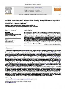
with Ψ(0) = 1 and x ∈ [0, 1]. The analytic solution is Ψa (x) =
e−x /2 1+x+x3
+ x2 and is displayed
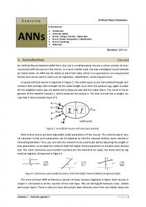
in Figure 1a. According to equation (11) the trial neural form of the solution is taken to be: Ψt (x) = 1+xN(x, p~). The network was trained using a grid of 10 equidistant points in [0,1]. Figure 2 displays the deviation ∆Ψ(x) from the exact solution corresponding at the grid points (small circles) and the deviation at many other points in [0, 1] as well as outside that interval (dashed line). It is clear that the solution is of high accuracy, although training was performed using a small number of points. Moreover, the extrapolation error remains low for points near the equation domain. 4.1.2
Problem 2
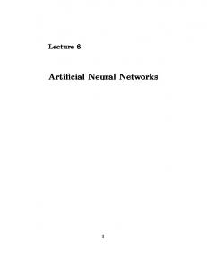
x 1 d Ψ + Ψ = e− 5 cos(x) dx 5 x with Ψ(0) = 0 and x ∈ [0, 2]. The analytic solution is Ψa (x) = e− 5 sin(x) and is presented in Figure 1b. The trial neural form is: Ψt (x) = xN(x, p~) according to equation (11). As before we used a grid of 10 equidistant points in [0,2] to perform the training. In analogy with the previous case, Figure 3
display the deviation ∆Ψ(x) at the grid points (small circles) and at many other points inside and outside the training interval (dashed line).
8
4.1.3
Problem 3
d2 1 d 1 −x Ψ + Ψ + Ψ = − e 5 cosx dx2 5 dx 5 d Consider the initial value problem: Ψ(0) = 0 and dx Ψ(0) = 1 with x ∈ [0, 2]. The exact solution is: x −5 Ψ(x) = e sin(x) and the trial neural form is: Ψt (x) = x + x2 N(x, p~) (from equation (13)). 1 Consider also the boundary value problem: Ψ(0) = 0 and Ψ(1) = sin(1)e− 5 , x ∈ [0, 1]. The exact 1
solution is the same as above, but the appropriate trial neural form is: Ψt (x) = xsin(1)e− 5 + x(1 − x)N(x, p~) (from equation (14)). Again as before we used a grid of 10 equidistant points and the plots of the deviation from the exact solution are displayed at Figures 4 and 5 for the initial value and boundary value problem respectively. The interpretation of the figures is the same as in the previous cases. From all the above cases it is clear that method can handle effectively all kinds of ODEs and provides analytic solutions that remain to be of the same accuracy at points other from the training ones. 4.1.4
Problem 4
Consider the system of two coupled first order ODEs: d Ψ1 = cos(x) + Ψ21 + Ψ2 − (1 + x2 + sin2 (x)) dx d Ψ2 = 2x − (1 + x2 )sin(x) + Ψ1 Ψ2 dx with x ∈ [0, 3] and Ψ1 (0) = 0 and Ψ2 (0) = 1. The analytic solutions are Ψa1 (x) = sin(x) and Ψa2 (x) = 1 + x2 and are displayed at Figure 6a and 6b, respectively. Following equation (15) the trial neural solutions are: Ψt1 (x) = xN1 (x, ~p1 ) and Ψt2 (x) = 1 + xN2 (x, ~p2 ) where the networks N1 and N2 have the same architecture as in the previous cases. Results concerning the accuracy of the obtained solutions at the grid points (small circles) and at many other points (dashed line) are presented in Figure 7.
4.2
PDEs
We consider boundary value problems with Dirichlet and Neumann BCs. All subsequent problems were defined on the domain [0, 1] × [0, 1] and in order to perform training we consider a mesh of 100 points obtained by considering 10 equidistant points of the domain [0, 1] of each variable. In analogy with the previous cases the neural architecture was considered to be a MLP with two inputs (accepting the coordinates x and y of each point), 10 sigmoid hidden units and one linear output unit. 9
4.2.1
Problem 5 ∇2 Ψ(x, y) = e−x (x − 2 + y 3 + 6y)
with x, y ∈ [0, 1] and the Dirichlet BCs: Ψ(0, y) = y 3 , Ψ(1, y) = (1 + y 3)e−1 and Ψ(x, 0) = xe−x , Ψ(x, 1) = e−x (x + 1). The analytic solution is Ψa (x, y) = e−x (x + y 3) and is displayed in Figure 8. Using equation (17) the trial neural form must be written: Ψt (x, y) = A(x, y) + x(1 − x)y(1 − y)N(x, y, ~p) and A(x, y) is obtained by direct substitution in the general form given by equation (18): A(x, y) = (1 − x)y 3 + x(1 + y 3 )e−1 + (1 − y)x(e−x − e−1 ) + y[(1 + x)e−x − (1 − x − 2xe−1 )] Figure 9 presents the deviation ∆Ψ(x, y) of the obtained solution at the 100 grid points that were selected for training while Figure 10 displays the deviation at 900 other points of the equation domain. It clear that the solution is very accurate and the accuracy remains high at all points of the domain. 4.2.2
Problem 6
2 1 a2 4 {[− a3 x − + 2a2 ]cos(a2 x2 + y) + [ − 1 − 4a4 x2 + ]sin(a2 x2 + y)} 5 5 25 25 with a = 3, x, y ∈ [0, 1] and the Dirichlet BCs as defined by the exact solution Ψa (x, y) = ∇2 Ψ(x, y) = e−
ax+y 5
ax+y
e− 5 sin(a2 x2 + y) (presented in Figure 11). Again the trial neural form is: Ψt (x, y) = A(x, y) + x(1 − x)y(1 − y)N(x, y, ~p) and A(x, y) is obtained similarly by direct substitution in equation (18). Accuracy results are presented in Figure 12 for the training points and in Figure 13 for test points. It can be shown that the accuracy is not the same as in the previous example, but it can be improved further by considering a neural network with more than 10 hidden units. From the figures it is also clear that the test error lies in the same range as the training error. 4.2.3
Problem 7 ∇2 Ψ(x, y) = (2 − π 2 y 2 )sin(πx)
∂ with x, y ∈ [0, 1] and with mixed BCs: Ψ(0, y) = 0, Ψ(1, y) = 0 and Ψ(x, 0) = 0, ∂y Ψ(x, 1) = 2sin(πx). The analytic solution is Ψa (x, y) = y 2 sin(πx) and is presented in Figure 14. The trial
neural form is specified according to equation (19) Ψt (x, y) = B(x, y) + x(1 − x)y[N(x, y, ~p) − N(x, 1, p~) −
∂ N(x, 1, p~)] ∂y
where B(x, y) is obtained by direct substitution in equation (20). The accuracy of the neural solution is depicted in Figures 15 and 16 for training and test points respectively.
10
4.5 (a) (b) 4 3.5 3 2.5 2 1.5 1 0.5 0 -0.5 0
0.5
1
1.5
2
2.5
3
3.5
4
Figure 1: Exact solutions of ODE problems 4.2.4
Problem 8
This is an example of a non-linear PDE. ∇2 Ψ(x, y) + Ψ(x, y)
∂ Ψ(x, y) = sin(πx)(2 − π 2 y 2 + 2y 3 sin(πx)) ∂y
with the same mixed BCs as in the previous problem. The exact solution is again Ψa (x, y) = y 2 sin(πx) and the parametrization of the trial neural form is the same as in problem 7. No plots of the accuracy are presented since they are almost the same with those of problem 7.
4.3
Comparison with Finite Elements
The above PDE problems were also solved with the finite element method which has been widely acknowledged as one of the most effective approaches to the solution of differential equations. The characteristics of the finite element method employed in this work are briefly summarized below. In the finite element approach the unknowns are expanded in piecewise continuous biquadratic elements [10]: Ψ=
9 X
Ψi Φi (ξ, n)
(22)
i=1
where Φi is the biquadratic basis function and Ψi is the unknown at the ith node of the element. The physical domain (x, y) is mapped on the computational domain (ξ, n) through the isoparametric
11
0.02
0
Solution Accuracy
-0.02
-0.04
-0.06
-0.08
-0.1
-0.12
-0.14 0
0.2
0.4
0.6
0.8
1 x
1.2
1.4
1.6
1.8
2
Figure 2: Problem 1: Accuracy of the computed solution.
0.001 0 -0.001
Solution Accuracy
-0.002 -0.003 -0.004 -0.005 -0.006 -0.007 -0.008 -0.009 -0.01 0
0.5
1
1.5
2 x
2.5
3
3.5
Figure 3: Problem 2: Accuracy of the computed solution.
12
4
0.0008
0.0007
0.0006
Solution Accuracy
0.0005
0.0004
0.0003
0.0002
0.0001
0
-0.0001 0
0.5
1
1.5
2 x
2.5
3
3.5
4
Figure 4: Problem 3 with initial conditions: Accuracy of the computed solution.
0.0006
0.0005
Solution Accuracy
0.0004
0.0003
0.0002
0.0001
0
-0.0001 0
0.2
0.4
0.6
0.8
1 x
1.2
1.4
1.6
1.8
2
Figure 5: Problem 3 with boundary conditions: Accuracy of the computed solution.
13
10 (a) (b) 8
6
4
2
0 0
0.5
1
1.5
2
2.5
3
Figure 6: Exact solutions of the system of coupled ODEs.
0 (a) (b)
-2e-05 -4e-05
Solution Accuracy
-6e-05 -8e-05 -0.0001
-0.00012 -0.00014 -0.00016 -0.00018 -0.0002 0
0.5
1
1.5 x
2
2.5
Figure 7: Problem 4: Accuracy of the computed solutions.
14
3
1
0.5
0 1
0
0.5
y
0.5 x 1
0
Figure 8: Exact solution of PDE problem 5.
Solution Accuracy 5e-07 4e-07 3e-07 2e-07 1e-07 0 -1e-07 -2e-07 -3e-07 -4e-07 -5e-07 1
0
0.5
y
0.5 x 1
0
Figure 9: Problem 5: Accuracy of the computed solution at the training points.
15
Solution Accuracy 5e-07 4e-07 3e-07 2e-07 1e-07 0 -1e-07 -2e-07 -3e-07 -4e-07 -5e-07 1
0
0.5
y
0.5 x 1
0
Figure 10: Problem 5: Accuracy of the computed solution at the test points.
"tape2"
1
0.5
0
-0.5 1
-1 0
0.5 0.5 x 1
0
Figure 11: Exact solution of PDE problem 6.
16
y
Solution Accuracy 0.0015 0.001 0.0005 0 -0.0005 -0.001
1
0
0.5
y
0.5 x 1
0
Figure 12: Problem 6: Accuracy of the computed solution at the training points.
Solution Accuracy 0.0015 0.001 0.0005 0 -0.0005 -0.001 1
0
0.5
y
0.5 x 1
0
Figure 13: Problem 6: Accuracy of the computed solution at the test points.
17
"tape2"
1 0.9 0.8 0.7 0.6 0.5 0.4 0.3 0.2 0.1 0 -0.1 1
0
0.5
y
0.5 x 1
0
Figure 14: Exact solution of PDE problems 7 and 8.
Solution Accuracy 6e-06 5e-06 4e-06 3e-06 2e-06 1e-06 0 -1e-06 -2e-06 -3e-06 -4e-06 1
0
0.5
y
0.5 x 1
0
Figure 15: Problem 7: Accuracy of the computed solution at the training points.
18
Solution Accuracy 6e-06 5e-06 4e-06 3e-06 2e-06 1e-06 0 -1e-06 -2e-06 -3e-06 -4e-06 -5e-06 1
0
0.5
y
0.5 x 1
0
Figure 16: Problem 7: Accuracy of the computed solution at the test points. mapping: x=
9 X
xi Φi (ξ, n)
(23)
9 X
yi Φi (ξ, n)
(24)
i=1
y=
i=1
where ξ and n are the local coordinates in the computational domain (0 ≤ ξ, n ≤ 1) and xi , yi the ith node coordinates in the physical domain for the mapped element. The used Galerkin Finite Element Method (GFEM) calls for the weighted residuals Ri to vanish at each nodal position i: Ri =
Z
D
G(x, y)det(J)dξdn = 0
(25)
where G is given by equation (1) and J is the Jacobian of the isoparametric mapping: det(J) =
∂x ∂y ∂x ∂y − ∂ξ ∂n ∂n ∂ξ
(26)
This requirement along with the imposed boundary conditions constitute a set of nonlinear algebraic equations (Ri = 0). The inner products involved in the finite element formulation are computed using the nine-node Gaussian quadrature. The system of equations is solved for the nodal coefficients of the basis function expansion using the Newton’s method forming the Jacobian of the system explicitly (for both linear and nonlinear differential operators): ~ (n+1) = −R ~ B∆Ψ 19
(27)
Neural Method Problem No. Training set Interpolation set 5 5 × 10⁻⁷ 5 × 10⁻⁷ 6 0.0015 0.0015 −6 7 6 × 10 6 × 10⁻⁶ 8 1.5 × 10⁻⁵ 1.5 × 10⁻⁵
Finite Element Training set Interpolation set 2 × 10⁻⁸ 1.5 × 10⁻⁵ 0.0002 0.0025 −7 7 × 10 4 × 10⁻⁵ 6 × 10⁻⁷ 4 × 10⁻⁵
Table 1: Maximum deviation from the exact solution for the neural and the finite element methods. ~ (n+1) = Ψ ~ (n) + ∆Ψ ~ (n+1) Ψ
(28)
where the superscript n denotes the iteration number and B is the global Jacobian of the system of ~ equations R: ∂Ri Bij = (29) ∂Ψj ~ (0) is chosen at random. For linear problems convergence is achieved in one The initial guess Ψ iteration and for non-linear problems in 1-5 iterations. All PDE problems 5-8 are solved on a rectangular domain of 18× 18 elements resulting in a linear system with 1369 unknowns. This is in contrast with the neural approach which assumes a small number of parameters (30 for ODEs and 40 for PDEs), but requires more sophisticated minimization algorithms. As the number of employed elements increases the finite element approach requires an excessive number of parameters. This fact may lead to memory requirements that exceed the available memory resources. In the finite element case, interpolation is performed using a rectangular grid of 23 × 23 equidistant points (test points). For each pair of nodal coordinates (x, y) of this grid, we correspond a pair of local coordinates (ξ, n) of a certain element of the original grid where we have performed the computations. The interpolated values are computed as: Ψ(ξ, n) =
9 X
Ψi Φi (ξ, n)
(30)
i=1
for the element that corresponds to the global coordinates (x, y). It is clear that the solution is not expressed in closed analyical form as in the neural case, but additional computations are required in order to find the value of the solution at an arbitrary point in the domain. Figures 17-22 display the deviation |Ψ(x, y)−Ψa(x, y)| for PDE problems 5-7 (figures concerning problem 8 are similar to those of problem 7). For each problem two figures are presented displaying the deviation at the training set and at the interpolation set of points respectively. Table 1 reports the maximum deviation corresponding to the neural and to the finite element method at the training and at the interpolation 20
Solution Accuracy 2e-08 1.5e-08 1e-08 5e-09 0 1
0
0.5
y
0.5 x 1
0
Figure 17: Problem 5: Accuracy of the FEM solution at the training points. set of points. It is obvious that at the training points the solution of the finite element method is very satisfactory and in some cases it is better than that obtained using the neural method. It is also clear that the accuracy at the interpolation points is orders of magnitude lower as compared to that at the training points. On the contrary, the neural method provides solutions of excellent interpolation accuracy, since, as Table 1 indicates, the deviations at the training and at the interpolation points are comparable. It must also be stressed that the accuracy of the finite element method decreases as the size of the grid becomes smaller, and that the neural approach considers a mesh of 10×10 points while the in the finite element case a 18×18 mesh was employed.
5
Conclusions and Future Research
A method has been presented for solving differential equations that relies upon the function approximation capabilities of the feedforward neural networks and provides accurate and differentiable solutions in a closed analytic form. The success of the method can be attributed to two factors. The first one is the employment of neural networks that are excellent function approximators and the second is the form of the trial solution that satisfies by construction the BCs and therefore the constrained optimization problem becomes a substantially simpler unconstrained one. Unlike most previous approaches, the method is general and can be applied to both ODEs and PDEs by constructing the appropriate form of the trial solution. As indicated by our experiments the method exhibits excellent generalization performance since the deviation at the test points was
21
1.5e-05 Solution Accuracy
1e-05
5e-06
0 1
0
0.5
y
0.5 x 1
0
Figure 18: Problem 5: Accuracy of the FEM solution at the test points.
Solution Accuracy 0.00025 0.0002 0.00015 0.0001 5e-05 0 1
0
0.5
y
0.5 x 1
0
Figure 19: Problem 6: Accuracy of the FEM solution at the training points.
22
Solution Accuracy 0.0025 0.002 0.0015 0.001 0.0005 0 1
0
0.5
y
0.5 x 1
0
Figure 20: Problem 6: Accuracy of the FEM solution at the test points.
Solution Accuracy 7e-07 6e-07 5e-07 4e-07 3e-07 2e-07 1e-07 0 1
0
0.5
y
0.5 x 1
0
Figure 21: Problem 7: Accuracy of the FEM solution at the training points.
23
Solution Accuracy 4e-05 3.5e-05 3e-05 2.5e-05 2e-05 1.5e-05 1e-05 5e-06 0 1
0
0.5
y
0.5 x 1
0
Figure 22: Problem 7: Accuracy of the FEM solution at the test points. in no case greater than the maximum deviation at the training points. This is in contrast with the finite element method where the deviation at the testing points was significantly greater than the deviation at the training points. We note that the neural architecture employed was fixed in all the experiments and we did not attempt to find optimal configurations or to study the effect of the number of hidden units on the performance of the method. Moreover, we did not consider architectures containing more than one hidden layers. A study of the effect of the neural architecture on the quality of the solution constitutes one of our research objectives. Another issue that needs to be examined is related with the sampling of the grid points that are used for training. In the above experiments the grid was constructed in a simple way by considering equidistant points. It is expected that better results will be obtained in the case where the grid density will vary during training according to the corresponding error values. This means that it is possible to consider more training points at regions where the error values are higher. It must also be stressed that the proposed method can easily be used for dealing with domains of higher dimensions (three or more). As the dimensionality increases, the number of training points becomes large. This fact becomes a serious problem for methods that consider local functions around each grid point since the required number of parameters becomes excessively large and, therefore, both memory and computation time requirements become intractable. In the case of the neural method the number of training parameters remains almost fixed as the problem dimensionality increases. The only effect on the computation time stems from the fact that each training pass
24
requires the presentation of more points, i.e. the training set becomes larger. This problem can be tackled by considering either parallel implementations, or implementations on a neuroprocessor that can be embedded in a conventional machine and provide considerably better execution times. Such an implementation on neural hardware is one of our near future objectives, since it will permit the treatment of many difficult real world problems. Finally we aim at extending the approach to treat other problems of similar nature, as for example eigenvalue problems for differential operators. One of us (I. E. L.) acknowledges partial support from the General Secretariat of Research and Technology under contract PENED 91 ED 959.
25
References [1] Kincaid, D. and Cheney, W., Numerical Analysis, Brooks/Cole Publishing Company, 1991. [2] Lee, H. and Kang, I., Neural algorithms for solving differential equations, Journal of Computational Physics, vol. 91, pp. 110-117, 1990. [3] Meade Jr, A.J. and Fernadez, A.A., The numerical solution of Linear Ordinary Differential Equations by Feedforward Neural networks, Math. Comput. Modelling, vol. 19, no. 12, pp. 1-25, 1994. [4] Meade Jr, A.J. and Fernadez, A.A., Solution of Nonlinear Ordinary Differential Equations by Feedforward Neural networks, Math. Comput. Modelling, vol. 20, no. 9, pp. 19-44, 1994. [5] Wang, L. and Mendel J.M., Structured trainable networks for matrix algebra, IEEE Int. Joint Conference on Neural Networks, vol. 2, pp. 125-128, 1990. [6] Yentis, R. and Zaghoul, M.E., VLSI Implementation of Locally Connected Neural Network for Solving Partial Differential Equations, IEEE Trans on Circuits and Systems-I, vol. 43, no. 8, pp. 687-690, 1996. [7] Evangelakis, G.A. and Rizos, J.P. and Lagaris, I.E. and Demetropoulos, I.N., MERLIN - A portable system for multidimensional minimization, Computer Physics Communications, vol. 46, pp 401-415, 1987. [8] Papageorgiou D. G., Chassapis C. S. and Lagaris I. E., MERLIN–2.0 Enhanced and Programmable Version, Computer Physics Communications, vol. 52, pp. 241-247, 1988. [9] Fletcher R., Practical methods of Optimization, second edition, John Wiley 1987. [10] Zienkiewicz, O.C. and Taylor, R.L., The Finite Element Method, 4th Edition, vol. 1, Mc-Graw Hill, 1989.
26