Artificial pulse generator triggers LOFAR radio telescope M.J. Norden The Netherlands Institute for Radio Astronomy Astron, Postbus 2, 7990 AA Dwingeloo, The Netherlands
[email protected] Abstract— LOFAR is a radio synthesis telescope existing of at least 37 stations in The Netherlands and 8 European stations. One of the operation modes of the telescope is to detect and trigger on short (nS) electro-magnetic pulses. These pulses originate from ultra-high energy cosmic rays but also from earth based sources like motor sparking, lightning or electric fences. Strong cosmic ray signals are rare and come from any direction in the sky. A cheap artificial pulse generator is developed to trigger the LOFAR radio telescope. This simplifies testing of the self trigger algorithms and is also useful for system testing and validation. Keywords— LOFAR, comic ray, self trigger, pulse, testing and validation
I. INTRODUCTION The LOw Frequency antenna ARray (LOFAR) exists of at least 37 Dutch and 8 European astronomy stations, each with two different types of antenna arrays. A low band antenna (LBA) array requires 82 m diameter and a high band antenna (HBA) array exist of 48 (96 for international) tiles of 25 m2 each. For the experiments described in this paper the LBA outer array is used. A low band antenna design is optimized to receive electromagnetic waves within a frequency range of 30 up to 80 MHz. The antenna has an inverted V shape with a half-wavelength dipole of 2.8 meter. All 48 LBA outer antennas have two orthogonal placed dipoles. The 96 polarised signals are amplified with a low noise amplifier and distributed to the receiver units inside the LOFAR cabinet. A schematic drawing of a low band antenna is given in Fig. 1.
The LOFAR Cosmic Ray Key Science Project (CRKSP) aims to detect radio signals of very high energy cosmic rays in the atmosphere and ultra-high energy cosmic rays and neutrinos hitting the Moon. The particle cascade that develops when such a high energy particle interacts causes the emittance of a short (nS) broadband electromagnetic pulse [5, 6] that could be detected with LOFAR. A self trigger algorithm that runs either at station level, or for weaker signals using the combined signal of many stations, at the LOFAR central processing facility, continuously scans the data online for candidate cosmic ray pulses. Upon finding a suitable candidate, a trigger can be issued to dump the raw voltage data of all dipoles. Strong cosmic ray signals are rare and can come from any direction in the sky. An artificial pulse from a known location could simplify the test of the self trigger algorithms. II. PULSE GENERATOR The artificial pulse generator design should be portable, light weight, small in size and preferably cheap. The pulse duration should be short (10-100nS) but has to contain sufficient energy to trigger all low band antennas on a station. The pulse signal received by the LOFAR station is amplified, filtered and digitized by means of a 12 bit analogue to digital converter [1]. The analogue signal is sampled with 200 million samples per second (MSPS) leading to a time resolution of 5 nS. The voltage samples are stored in a so called Transient Buffer Boards (TBB). A TBB contains 8/32 Gigabytes of memory, sufficient to store 1.3/5.2 seconds of time series data [2, 3] per antenna polarisation. The time samples are stored in a ring buffer and once the input signal passes a predefined trigger level the recording stops. The captured data is packed and transported by fibre to a central storage node. The data files are time-stamped with the trigger date and time for offline processing. A short pulse could be generated by a piezo-electronic igniter but a disadvantage is that it is hard to generate a constant pulse because the mechanical pressure varies. With the use of an electronic high voltage generator and magnetic loop antenna the generation of a constant electromagnetic pulse is much easier. The current in the loop is limited by a series resistor. By varying the value of this resistor the duration and strength of the pulse could be optimized.
Fig.1 LBA dipole
A cheap and small high voltage generator was found inside an electronic fly swatter. The voltage is about 2kV but the electric charge capacity is limited to 45 μC. When the high voltage capacitor is discharged in 100nS the total current is still 450 Ampere. The peak current is smaller because the voltage drops when the capacitor is loaded by closing the loop. The loop impedance determines the shape, frequency and strength of the electromagnetic pulse. A special switch is used inside the fly swatter. When the switch is pressed an oscillator circuit starts charging the high voltage capacitor. When the switch is released the charging stops and the loop will be closed causing a controlled current Fig. 3 Schematic high voltage generator. flowing through the inductance of the loop. A controlled The simulation results of the high voltage circuit shows stable pulse is generated as the high voltage capacitor is with a blue trace the current through resistor R1. Once the base discharged. A photograph of the modified fly swatter is given in Fig. 2. current of Q1 is positive the current through L2 starts to increase rapidly (red trace). The magnetic field generated by The red wire forms a loop with an area of 25cm2. L2 is opposite and stronger then the field generated by coil L1.The current through L1 changes polarity and Q1 stops conducting. This process repeats every 180 μs by itself. The simulation results are given in Fig. 4.
Fig. 2 Artificial pulse generator.
A. Simulation model First an attempt was made to understand the working of the high voltage generation circuit. By reverse engineering the electronic design a simulation schematic was made. The circuit was simulated using models of the individual components. The central transformer uses three coils around a single iron core. The coils indicated with L2 and L3 are respectively the primary and secondary windings of the transformer. A high winding ratio is used to boost the voltage at the secondary side of the transformer. The high voltage is stored in capacitor C1. The inductance of coil L1 and L2 are equal but they have opposite winding polarity. The circuit starts when S1 closes. A current starts to flow in loop 1, formed by resistor R1, inductor L1 and transistor Q1. This causes a second higher current to flow in the loop 2 formed by S1, L2 and Q1. Because the winding polarity of L1 and L2 are different an opposite but current will be generated in L1. Transistor Q1 stops conducting and the first charge cycle ends. As long as S1 is closed, capacitor C1 is charged. The oscillation frequency is audible and around 5.4 kHz. A schematic of the high voltage generator is given in Fig. 3.
Fig. 4 Blue trace current I(R1), red trace current I(L2).
B. The magnetic loop The loop formed by the high voltage capacitor C1 and the wire inside the racket can generate a magnetic field. The generation of the magnetic field starts once S2 is closed (Fig. 5). By construction S1 opens when S2 closes. A discharge current will flow through the loop inductance. The current is limited with a 3300 Ω series resistor. The current in loop 3 will generate a magnetic field around this wire. The electric energy of capacitor C1 is converted into a magnetic energy. Once capacitor C1 is discharge the generation of the magnetic field stops. The magnetic field polarity reverses and charges capacitor C1. This cycle repeats a few times until all energy is used. A schematic drawing of the magnetic loop is given in Fig. 5.
Fig. 5 Schematic drawing magnetic loop.
The generated electromagnetic pulse is a damped oscillation with a frequency of about 74 MHz. This frequency fits well inside the LOFAR frequency range of 30 up to 80 MHz. An advantage is that the signal is narrow band and therefore easier to distinguish among other received signals or pulses. The self trigger parameters of the TBBs were adjusted such, that it would mainly trigger on these artificial test pulses. To determine the equivalent inductance of the wire inside the racket frame a complex electro-magnetic simulation is required. In this paper we only tried to estimate the order of loop inductance L4. The loop inductance L4 is derived from the known capacitor value C1 of 22nF and the oscillation frequency f0 of 74 MHz.
L4 =
1 ⎛ 1 ⎞ ⎟ ∗⎜ C1 ⎜⎝ 2 ⋅ π ⋅ f 0 ⎟⎠
2
Fig. 6 Measurement setup artificial pulse generator.
III. EXPERIMENTAL VERIFICATION The artificial pulse generator was tested at one of the Dutch remote stations called RS307. This station has two low band antenna arrays with 48 LBA’s each. For this experiment we used the sparser LBA_OUTER array. This array configuration has the most distant antennas and distributed in a ring without having antennas in the centre. The pulse was generated at 10 meter distance from antenna 94 orthogonal with the Ypolarization of this antenna. A plot of the LBA_OUTER array is given in Fig. 7. The position where the pulse was generated is drawn in the plot as “Pulse position”.
(1)
The loop inductance is only 21 nH. Resistor R2 is used to fine tune the duration and strength of the generated pulse. The value of 3300 Ω was found to be a good compromise between pulse strength and duration. C. Testing Before the fly swatter could be used on a LOFAR station it was measured to check pulse strength, duration and shape. The generated pulse is measured with a current probe attached to an oscilloscope. The current probe has a transfer impedance of 1Ω. The output impedance of the probe is 50Ω and is connected by coaxial cable to an oscilloscope. The measured output voltage signal is proportional to the strength and direction of the current generated in the fly swatter loop. The peak current is about 20 Ampere and decays within 180nS. The pulse is symmetrical with an oscillation period of 13.5nS. The pulse satisfies the requirement that it should be short and could be well measured with a time resolution of 5nS in the LOFAR low band frequency band. A photo of the measurement setup and output signal is given in Fig. 6.
Fig. 7 LBA_OUTER antenna array layout station RS307.
The pulse was strong enough to trigger all 48 dipoles on both X- and Y polarisation. The LBA array was triggered on 11 January 2012 at 13:46:24 local time. The data was stored by six transient buffer boards and send to the CEntral Processing facility (CEP) in Groningen. The received antenna signal has 12-bit amplitude resolution and 5nS time resolution. In Fig. 8 a plot from three different antenna Y-polarizations is shown. The green pulse is from the nearest antenna 94-Y and
the black pulse from one of the most distant antenna 90-Y. The pulse height is more then the maximum value of ± 2048 ADC counts. For future experiments a distance of 20 meter would be better to prevent possible ADC clipping. Although it’s difficult to see in this plot the sampled signal looks very similar with the measured pulse in Fig 6.
Fig 8 Pulse received on antenna 94-Y (green), antenna 50-Y (red) and antenna 90-Y (black) with 5nS resolution.
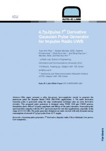
When the arrival time of antenna 94-Y is subtracted from the arrival time of the other antennas we get a distribution with time lags per antenna for this station. The delays per antenna number are plotted in Fig. 9.
between 120nS and 210nS. Above 63 meter distance the orange/red group is marked with the smallest dots indicating the weakest pulse signals. IV. CONCLUSIONS With only a few additional components a cheap fly swatter was modified to generate pulses to trigger all low band antennas on a LOFAR station. For a first prototype and field test the results were encouraging. Still we have some doubts about the reproducibility of the pulse strength and duration. A more sophisticated design of the high voltage generator could be a next step. The TBB trigger algorithm worked well but was found to be sensitive to other pulses as well, like nearby mobile phone activity. The trigger settings need to be fine-tuned and stored in a template for future testing and verification of the LOFAR system. A distance of 20 meter or more from the closest antenna is advised to prevent clipping of the received signal. A smaller loop resistor value can be used to increase the strength but will also reduce the length of the pulse. The pulse generator could be used to check the polarity of the LBA dipoles. For example an X-Y polarisation swap in the interconnection could be detected. This and other useful system tests are planned for the near future. REFERENCES [1] [2] [3] [4]
[5] [6]
Fig. 9 Pulse arrival time station RS307 in seconds.
The diameter of the dots indicates the strength of the pulse and scale with the square root of the power. The colours are indicating the delay. The maximum measured delay is about 275 nS. This matches well with the maximum distance of 82 meter between antenna 94 and antenna 90. Three groups of delays could be distinguished. The first group blue is within 120nS (36m) from antenna 94. The second group green is
M.J. Norden, G.W. Kant, “RCU II Signal Analysis and Specification”, ASTRON-SRS-014, Dwingeloo, 23 March 2007, unpublished. G.W. Schoonderbeek, A.W. Gunst, “Transient Buffer Board Specification”, ASTRON-RPT-065, Dwingeloo, 5 September 2007, unpublished G.W.Schoonderbeek, “Transient Buffer Board rev. 2.1 Description”, ASTRON-MAN-015, Dwingeloo, 11 November 2007, unpublished. J. Hagmann, S. Dickmann, M. Schaarschmidt, and S. Potthast, “Application of transient pulses on power supply networks using COTS hardware,” in EMC Europe, International Symposium on Electromagnetic Compatibility, Wroclaw, Poland, Sep. 2010, pp. 390–395. A. Horneffer, et al. “Cosmic ray and neutrino measurements with LOFAR”, Nucl. Instr. And Meth., A 617, 482, (2010). M. Mevius, et al. “Detecting ultra high energy neutrinos with LOFAR”, Nucl. Instr. And Meth., A 662, S26, (2012)