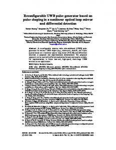
International Journal of Sciences: Basic and Applied Research (IJSBAR) ISSN 2307-4531 (Print & Online) http://gssrr.org/index.php?journal=JournalOfBasicAndApplied
---------------------------------------------------------------------------------------------------------------------------
Developing UWB Pulse Generator with Output Split Inverters for Breast Imaging System Sara Fouada, Reda Ghonameb, Abdelmonem Elmahdyc, Abdelh Zekryd a,c
Electronics and Communications Eng. Dept., Higher Institute of Engineering, Modern Academy, Cairo, Egypt.
b,d
Electronics and Communications Eng. Dept., Faculty of Engineering, Ain Shams University, Cairo, Egypt a
Email:
[email protected]
Abstract A digital glitch monocycle pulse generator in a standard 0.13-μm CMOS technology is designed for breast cancer imaging system. A successful low power pulse generator is proposed whose central frequency is digitally controlled to cover 5.2 GHz. The generator is based on delay gate of Output Split Inverter (OSI).The OSI consists of an inverter with current limiting transistor which controls the biasing voltage digitally. The biasing circuit contains current mirror, PMOS transistor which enables 96.5𝑝𝑝𝑝𝑝 delay values. A glitch circuit is designed for a monocycle pulse width of 193 𝑝𝑝𝑝𝑝 thought for breast cancer detection application. The proposed generator
consumes 369 µw at 200 MHz pulse repetition frequency (PRF), and 1.2 V power supply voltage. Its design layout area amounts 67.2× 43.7 µm2 .
Keywords: Pulse generator; Gaussian monocycle; Ultra Wideband; digital OSI; glitch generator; breast cancer. 1. Introduction Breast cancer is one of the main causes of women death [1, 2]. An early detection of tumor existence increases the chance of successful treatment and quick recovery.
-----------------------------------------------------------------------* Corresponding author.
85
International Journal of Sciences: Basic and Applied Research (IJSBAR)(2016) Volume 26, No 1, pp 85-97
The X-ray mammogram is the primary technique used in breast cancer detection. However, this technique poses several problems, such as the use of ionizing radiation, breast compression, complications in its use especially for younger women [1], and difficulty in detecting early tumors. Microwave breast tumor detection is a non-invasive technique which uses a non-ionizing radiation and it is also considered a potential alternative to X-rays [3, 4]. The tumor detection principle is based on analyzing the contrast in the dielectric properties between the healthy and malignant tissues [3]. Ultra-wideband (UWB) communications is one of the newest technologies employed in imaging systems that are utilized for human’s body imaging. The motivation is mainly based on using ultra-narrow pulses in the time domain to detect and contrast between normal and malignant tissues. The frequency range between 1 and 10 GHz is the optimum band for this application. This band showed high spatial resolution especially at higher frequencies and good penetration depth mainly at lower frequencies [5]. Transmitter circuit is an important part in UWB systems; it represents the reference to define the other parts of the system. In this way, the circuit of the UWB pulse generator is the main obstacle in the transmitter, which must provide an adequate signal level for the requirements of the proposed application. It must have a minimum of energy consumption and cost [6]. UWB pulse generators can primarily be classified in accordance with the shape of the pulse to: •
Gaussian pulse,
•
Monocycle pulse, and
•
Multicycle pulse.
A Gaussian pulse has the Gaussian shape whose frequency spectrum does not meet the FCC regulations, because the bandwidth is too large, and contain a dc value [6]. Monocycle pulses [7] are preferred to simple pulses because they have no dc components, which could represent a limit for the spectral mask compliance and radiation antenna efficiency. As well as the case for UWB frequency range from 3.1 GHz to 10.6GHz. In particular, for the UWB monocycle pulse generator, the main design challenges consist of reaching a very short duration time for mask compliance, the adequate amplitude to drive directly the antenna without requiring any additional amplification, and the full integration on silicon. There are many ways to generate monocycle pulses: one of these techniques is based on digital circuits and Gaussian filters. Gaussian filters are implemented by cascading small complex analog signal filters, which provide pseudo Gaussian monocycle pulses through the filtering of small signals (typically, triangular pulses) The aspects of the published pulse generators can be recognized at first glance by summarizing the performance of the most relevant works of the literature, which are reported here in after. In [9], a pulse duration time of 280ps, a peak-to-peak amplitude of 123 mV, and a power consumption of 12.6 mw from a 1.8-V supply is obtained for a fully integrated solution in a 0.18-𝜇𝜇m CMOS process by exploiting
86
International Journal of Sciences: Basic and Applied Research (IJSBAR)(2016) Volume 26, No 1, pp 85-97
the digital circuit approach. A monocycle pulse with a duration time of 500 ps and peak-to-peak amplitude close to 100 mV from a 1.8-V
supply voltage is produced in [10] using fully integrated solution in 0.18-𝜇𝜇m digital CMOS technology by exploiting distributed devices and analog and digital circuits. In [11], a monocycle pulse with duration time of 380ps, peak-to-peak amplitude of 660 mV, and a power consumption of 19.8 mw from a 1.2-V supply voltage are obtained with a fully integrated solution in a 90 nm
CMOS process by exploiting the triangular pulse generator approach.
In this work, a new an Output Split Inverter (OSI) [12],is designed and implemented as a delay element controlled digitally to obtain UWB monocycle pulse generated at 5.2 GHz center frequency to be compatible with breast cancer imaging system. The paper is organized as follows: the UWB breast cancer imaging system description is introduced in section 1.1, the Output Split Inverter (OSI) as a delay element controlled digitally to obtain a 96.5 𝑝𝑝𝑝𝑝 delay is explained in section 1.2, in section 1.3, a Glitch pulse generator using OSI and AND gate is presented to obtain Gaussian
pulse. The combining between a Gaussian and its inverted pulse results in 193 ps monocycle pulse by using pulse shaping transistor and capacitor. The Simulation results and calculations using cadence virtuoso tools are presented in section1.4, while section 1.5 concludes the paper. 1.1. System description Ultra-wideband (UWB) communication is one of the latest techniques used in imaging systems for human body. It is mainly based on the use of ultra-narrow pulses in the time domain to detect and get a useful contrast between normal and malignant tissue. The building blocks of the UWB transceiver are shown in Figure.1.
Figure 1: Transceiver of ultra wideband system. Medical imaging systems of UWB have significant differences compared with the narrow band systems. The
87
International Journal of Sciences: Basic and Applied Research (IJSBAR)(2016) Volume 26, No 1, pp 85-97
base one is that, there is no carrier in this type of communication. There is no need to modify, the most complex blocks used in the transfer of conventional continuous wave systems. The absence of these complex components makes UWB transmitter architecture inexpensive and simpler in design and easier in implementation with respect to conventional radio systems. From this point of view, UWB system block diagram is much simpler than the narrow band. The pulse generator circuit is the main block of the transmitter. It is a critical part in UWB systems and it is a reference to define the other parts of the system. The receiver architecture consists of three major blocks: a lownoise amplifier (LNA), a correlation circuitry and a block for providing template waveform for correlation circuit. Analog filtering method is one of UWB generator methods. A common way of directly generating an UWB pulse without using a carrier is to first form a baseband impulse with very short time duration and a high frequency bandwidth. Then filter the impulse using a band-pass or a pulse shaping filter. Digital logic circuits can be employed to create baseband impulses. They consist of inverters to find a small delay got by a NOR gate to generate an impulse on every falling edge of a trigger signal as shown in Figure 2 and the relative timing of the signals at the input of the NOR gate is shown in the same figure also. The NOR gate is used to combine the falling edge of the trigger signal and its delayed inverted replica to form a positive impulse. NAND gates have also been used in place of the NOR gate to realize impulses with the opposite polarity on every rising edge of the trigger. In [14], high-speed current mode logic (CML) is used for the delay cell to create a baseband impulse with very short time duration of 75ps and at frequency spectrum out to 10 GHz. The generated impulse is then applied to the third-order LC ladder Bessel filter to form the UWB pulse. In the following sections a complete design of the pulse generator will be introduced. Our design is based on an output split inverter as a delay element instead of conventional inverter, as well as AND gates to obtain a Gaussian pulse. Then the Gaussian pulses will be combined to form monocycle pulses [16].
Figure 2: Digital logic for impulse generator. 1.2. Digital Delayed Output Split Inverter It is shown in [12] that the output split inverter (OSI) could be used as delay element instead of conventional
88
International Journal of Sciences: Basic and Applied Research (IJSBAR)(2016) Volume 26, No 1, pp 85-97
inverters. Its delay can be controlled by biasing of an extra pull down transistor connected in series with the initial pull down transistor. It employs the idea of reducing the output slope by discharging the output capacitance with the drain current of a current limiting transistor. The designed digital delayed output split inverter is depicted in Figure 3 [15]. It consists of a biasing circuit at the left and two cascaded split inverters followed by a conventional output inverter. The transistors M4, and M6
as is in the ordinary logic inverter while 𝑀𝑀5 and 𝑀𝑀8 act as current sources controlled by the gate voltage coming
from the reference circuit. In this way the pull down current can be controlled by these transistors and there by controlling the delay time between the input and output. The proposed OSI model from M4 to M11 are the main elements for achieving a comparable delay (96.5 ps),
which is used in pulse generator breast cancer imaging system. The controlling current of the split transistors is
adjusted by the biasing current mirrors of the transistor M2, . The discharging current is controlled by transistor
M5 acting as a current source. The passing current through this transistor is determined by the gate voltage
obtained from M2 which act as a diode. The gate voltage of M5 , is determined by the current passing through the
drain of M1 with applied voltage corresponding to logic 0 to control the circuit digitally. OSI is used in our delay element as a two stage to ensure stability and the output is taken from a conventional inverter. The circuit
diagram is shown in Figure 3.
DC
M1
M7
M4
M10
input Logic 0
M5
output
M8
M2 M11 M3
M6
M9
Figure 3: Digital controlled Output split Inverter. 1.3. Transmitter Design Now, the developed delay circuits are used to generate a monocycle pulse for the UWB transmitter. The schematic of the UWB transmitter is shown in Figures 4. It is designed to generate the monocycle pulse depicted in Fig 5. The UWB pulse generator is designed to produce glitches at the rising edges of the clock signal. In our circuit, the glitches are produced by passing the clock pulses either directly to one of the inputs of the AND gate and through an OSI delay network to the other input as depicted in Fig 5.The two identical glitch generators (GGs)are labeled as GGA, and GGB.
89
International Journal of Sciences: Basic and Applied Research (IJSBAR)(2016) Volume 26, No 1, pp 85-97
The GGA output is inverted and applied to PMOSFET M12 of the output pulse shaper; as a result, the pulse-
generator output voltage become VDD . The output signal of GGB (which is identical to GGA) is delayed using
an eight-stage inverter chain and applied to NMOSFET M13 that drives the output voltage to 0 V, and generate
the negative pulse.
The sizes of output pulse shaper stage transistors M12 and M13 have to be selected carefully for correct pulse shape. During the design procedure, the supply voltage is kept constant at its nominal value of 1.2 V. The gate
sizes for the building blocks are determined to have an UWB pulse of 193 ps. The transmitter output at the drains of pulse shaper transistors is applied to the package and off-chip printed circuit board (PCB) through a wire bond that can be simplified as an equivalent 2.5-nH inductance Lwb as shown in Figure 4 [16]. A 5.2 GHz-
band BPF is realized using a 0.2 pF series capacitance Cps withLwb .The proposed Monocycle pulses with 193
𝑝𝑝𝑝𝑝 pulse duration approximate 5.2 GHz center frequency operation is shown in Fig. 5.A Gaussian monocycle of 193-ps width is obtained after PEX test. The peak-to-peak voltage is 460 mV.
Figure 4: block diagram of the proposed transmitter. 1.4 Simulation results The proposed transmitter is simulated using cadence virtuoso assuming UMC MMRF 130-nm CMOS process. The layout is shown in Fig. 6 after DRC and LVS check. The whole transmitter including the Glitch generator and inverters occupies only an area of 67.2 µm × 43.7µm.
Slow-slow, Fast-Fast, and Typical-Typical tests at T=270 C is applied on monocycle pulse. The variation of the
amplitude and the pulse duration after Parasitic (PEX) extraction is shown in Table 1, and depicted in figure 7. The slow model parameters resulted in pulse duration of 207ps corresponding to center frequency of 4.8 GHz. While the fast model parameters resulted in pulse duration of 190 𝑝𝑝𝑝𝑝corresponding to a center frequency of 5.3
90
International Journal of Sciences: Basic and Applied Research (IJSBAR)(2016) Volume 26, No 1, pp 85-97
GHz. These values are compatible to breast cancer applications as presented in table 1 also. The pulse duration of S-S expanded to 225 ps at T=−200 C approximating frequency of 4.4 GHz, while F-F give a value approximating 5.6 GHz, as shown in Figure 8 and Table 2.
Figure 5: 193ps monocycle UWB pulse. Figure 9 and Table 3 shows that the pulse duration of S-S and F-F expanded to 250 ps and 210 𝑝𝑝𝑝𝑝 at T = 700
and center frequency approximating to 4GHZ, and 4.8GHz which is acceptable for UWB imaging breast cancer.
The comparison between the developed UWB PGs and previous monocycle generators [10, 11, 16, and 17] is presented in Table 4. From this table, it is seen that our UWB pulse generator has low power dissipation except [16], because the smaller band, and the smaller amplitude compared to ours. The distributed and triangular pulse generator as analog and digital pulse generator in [10, 11] have higher power consumption than ours one has to define some figure of merit for sake of fare comparison. 1.5 conclusions A proposed OSI element is designed as delay element to control the delay digitally. This OSI element is designed for providing 96.5 𝑃𝑃𝑃𝑃 delays to a pulse signal . A fully integrated monocycle pulse generator of a center frequency of about5.2 GHz UWB CMOS transmitter has been achieved. The designed OSI as a delay
91
International Journal of Sciences: Basic and Applied Research (IJSBAR)(2016) Volume 26, No 1, pp 85-97
element is used for breast cancer imaging system in SoaC pulse radar to obtain a monocycle pulse. This circuit provides a 460 -mV sinusoidal-like monocycle with a duration time of about 193 ps when it is activated by a positive edge of a low-frequency command signal. The overall power consumption amounts to 369 µw and the
layout area is 67.2 µm × 43.7µm . for strict comparison with the published one may introduce a suitable figure of merit.
Figure 6: layout of UWB monocycle pulse generator
Figure 7: Fast-Fast, Typical-Typical, and Slow-Slow monocycle pulse at 𝑇𝑇 = 270 𝐶𝐶.
92
International Journal of Sciences: Basic and Applied Research (IJSBAR)(2016) Volume 26, No 1, pp 85-97
Figure 8: Fast-Fast, Typical-Typical, and slow-slow monocycle pulse at T = −200 .
Figure 9: Fast-Fast, typical-Typical, and Slow-Slow monocycle pulse at𝑇𝑇 = 700 𝐶𝐶 .
93
International Journal of Sciences: Basic and Applied Research (IJSBAR)(2016) Volume 26, No 1, pp 85-97
Table 1: Model parameter at T=270 C. Model parameter
T-T
S-S
F-F
Amplitude 𝑉𝑉𝑃𝑃−𝑃𝑃
460 𝑚𝑚𝑚𝑚
400 𝑚𝑚𝑚𝑚
510 𝑚𝑚𝑚𝑚
Duration pulse𝜏𝜏
198𝑃𝑃𝑃𝑃
207 𝑃𝑃𝑃𝑃
190𝑃𝑃𝑃𝑃
Table 2: Model parameter at T=−200 C. Model parameter
T-T
F-F
S-S
Amplitude 𝑉𝑉𝑃𝑃−𝑃𝑃
500 𝑚𝑚𝑚𝑚
550 𝑚𝑚𝑚𝑚
420 𝑚𝑚𝑚𝑚
Duration pulse𝜏𝜏
193 𝑃𝑃𝑃𝑃
180𝑃𝑃𝑃𝑃
225 𝑃𝑃𝑃𝑃
Table 3: Model parameter at T=700 C. Model parameter
T-T
F-F
Amplitude 𝑉𝑉𝑃𝑃−𝑃𝑃
440 𝑚𝑚𝑚𝑚
470 𝑚𝑚𝑚𝑚
380 𝑚𝑚𝑚𝑚
Duration pulse𝜏𝜏
205 𝑃𝑃𝑃𝑃
210𝑃𝑃𝑃𝑃
250𝑃𝑃𝑃𝑃
94
S-S
International Journal of Sciences: Basic and Applied Research (IJSBAR)(2016) Volume 26, No 1, pp 85-97
Table 4: comparison performance Refs
This work
[10]
[11]
[16]
[17]
Freq-band [GHz]
5.2
-
-
0-0.960
7.2
Tech [𝜇𝜇𝜇𝜇]
0.13
0.9
0.18
0.13
0.18
𝑉𝑉𝑝𝑝𝑝𝑝
460
660
500
340
115
0.193
0.375
0.160
2
0.47
[𝑚𝑚𝑚𝑚] 𝜏𝜏
Pulse
[𝑛𝑛𝑛𝑛]
fifth monocycle
Type
monocycle
monocycle
monocycle
Derivate pulse
PRF
200
1
-
1
100
0.369
19.8
-
0.056
-
E/pulse pJ/p
1.845
19800
-
56
-
Figure of merits
108.4
5.056
-
0.01785
-
[MHZ]
[mw]
𝑃𝑃𝐷𝐷𝐷𝐷
[Mps]/[pJ/p]
10−5
×
References [1] Shao, W. and B. Zhou, “UWB microwave imaging for breast tumor detection in inhomogeneous tissue,” Proceedings of the 2005 IEEE Engineering in Medicine and Biology, 27th Annual Conference, Shanghai, China, pp. 1496–1499,2005. [2] Sill, J. M. and E. C. Fear, “Tissue sensing adaptive radar for breast cancer detection-experimental investigation of simple tumor models,” IEEE Transactions on Microwave Theory and Techniques, Vol. 53,pp. 1496–1499, 2005. [3] Fear, E. C., J. Sill, and M. A. Stuchly, “Experimental feasibility study of confocal microwave imaging for breast tumor detection," IEEE Trans. Microwave Theory Tech., Vol. 51, No. 3, , 887-892, 2003.
95
International Journal of Sciences: Basic and Applied Research (IJSBAR)(2016) Volume 26, No 1, pp 85-97
[4] Sill, J. M. and E. C. Fear, “Tissue sensing adaptive radar for breast cancer detection | Experimental investigation of simple tumor models," IEEE Trans. Microwave Theory Tech., Vol. 53,No. 11, pp. 33123319, 2005. [5] A. Lazaro, D. Girbau, and R. Villarino “Wavelet based breast tumor localization technique using UWB radar” Progress In Electro magnetics Research, PIER 98, 75-95, 2009 [6] M. Ghavami, L. B. Michael, and R. Kohno “Ultrawide band signal and systems in communication engineering” second dition ,Wiley2007. [7] X. Chen and S. Kiaei,“ Monocycle shaper for ultra wideband system,” in Proc. IEEE Int. Symp. Circuits Syst., Scottsdale, AZ, May 2002, pp. 597–600. [8] S. Bagga, A. V. Vorobyov, S. A. P. Haddad, A. G. Yarovoy, W. A.Serdijn, and J. R. Long, “Codesign of an impulse generator and miniaturized antennas for IR-UWB,” IEEE Trans. Microw. Theory Tech., vol.54, no. 4, pp. 1656–1666, Apr. 2006. [9] T. Kikkawa, P. K. Saha, N. Sasaki, and K. Kimoto, “Gaussian monocycle pulse transmitter using 0.18 um CMOS technology with on-chip integrated antennas for inter-chip UWB communication,” IEEE J. Solid-State Circuits, vol. 43, no. 5, , pp. 1303–1312, May 2008. [10] Y. Zhu, J. Zuegel, J. R. Marciante, and H. Wu, “Distributed waveform generator: A new circuit technique for ultra-wideband pulse generation, shaping and modulation,” IEEE J. Solid-State Circuits, vol. 44, no. 3, pp. 808–823, Mar. 2009. [11] F. Zito, D. Pepe, and D. Zito “UWB CMOS Monocycle Pulse Generator” IEEE transaction on circuits and systems, Vol. 57, No. 10, October 2010. [12] P. Mroszczyk, P. Dudek “Tunable CMOS Delay Gate With Improved Matching Properties” IEEE Trans. Circuits and systems, vol. 61, No. 9, , pp 2586-2595, Sept 2014. [13] H. K. Bidhendi, H. M. Jafari ,and R. Genov “UltraWide band Imaging Systems for Breast Cancer Detection” springer, 2014. [14] S. Bourdel, Y. Bachelet, J. Gaubert, R. Vauche, O. Fourquin, N. Dehaese, and H. Barthelemy, \A 9pJ/Pulse 1.42-Vpp OOK CMOS UWB pulse generator forthe 3.1-10.6-GHz FCC band," IEEE Transactions on Microwave Theory and Techniques, vol. 58, no. 1, , pp. 65-73, Jan. 2010. [15] M. Nejad, and M. Sachdev “A Digitally Programmable Delay Element: Design and Analysis” IEEE Very large scale integration systems, vol. 11, No. 5, oct. 2003. [16] O. Batur, E. Akda˘g, H. K. Akkurt, A. Öncü, M. Koca, and G. Dündar “An Ultra Low-Power DualBand IR-UWB Transmitter in 130-nm CMOS” IEEE transaction on circuits and systems, Vol.59,No. 11,
96
International Journal of Sciences: Basic and Applied Research (IJSBAR)(2016) Volume 26, No 1, pp 85-97
Nov. 2012. [17] S. H. Barboza, J. A. Palacio, E. Pontes and S. T. Kofuji “Fifth Derivative Gaussian Pulse Generator for UWB Breast Cancer Detection System” ICUWB conference, , pp. 269-273, Sept. 2014.
97