ASSEMBLY CODE CONVERSION THROUGH PATTERN MAPPING BETWEEN TWO VLIW DSP PROCESSORS: A CASE STUDY Bogong Su 1
[email protected]
Jian Wang 2
[email protected]
Abstract In this paper, we investigate a new pattern mapping method to convert the assembly code between two VLIW digital signal processors. The method is so named because the pattern of the code is kept unchanged during the conversion process in order to manage complexity. As a case study, we first manually convert the assembly code of a typical DSP application from Texas Instruments' TIC62, the source processor, to a high level intermediate code. We then feed the intermediate code to the SC140 compiler backend to generate the assembly code of the target SC140 processor, which is executed on the SC140 simulator. The result thus obtained compares favorably with that obtained directly by compiling and executing the C code on the SC140 system in terms of both validity and total execution cycles. 1. Introduction Digital signal processing industry has been growing rapidly over the past few years [1]. Due to the constant need to improve the performance and to address a wide range of applications, the manufacturers of digital signal processors have introduced a variety of processors of different designs over the years. Recently, a new breed of processors based on VLIW architecture has become mainstream. How to take advantage of these newer and more powerful processors by migrating existing code to these processors in a timely manner has become a problem of practical importance. Although binary code conversion between general-purpose processors has been investigated [2, 3, 4], few work has been done for code conversion between digital signal processors [5]. We have proposed an approach to convert the assembly code of traditional DSP processor to VLIW DSP processor [6]. In this paper, we are motivated to investigate the code conversion at assembly level between two different VLIW processors for the following considerations. Despite recent progress in compiler technologies, much of the application code is still 1 2
Erh-Wen Hu 1
[email protected]
Joseph Manzano 1
[email protected]
handcrafted and optimized at assembler level. Besides, as more and more VLIW DSP processors are available, code conversion between VLIW DSP processors becomes a new challenge. In the following section, we present our code conversion method. 2. Code Conversion Method In this section, we will present our pattern matching code conversion method that converts the optimized assembly code between two VLIW DSP processors. 2.1 Pattern Before we define the concept of pattern, we describe some important definitions. Basic Instructions and VLIW Instructions - A basic instruction is the instruction that performs only one operation such as addition, multiplication, memory load or store, register data transfer, and in some case, we also consider MAC as a basic instruction. A VLIW instruction is a group of basic instructions that can be issued for execution at the same time. In this paper, when we say instructions without putting VLIW in the front, we imply they are basic instructions. Basic Block and Control Flow Graph - A basic block is an instruction sequence that has only one entry and one exit. We use a directed graph to represent the control flow of a program, which is called a control flow graph. The control flow graph consists of all basic blocks of a program as its nodes and directed edges that specify the execution order of the basic blocks. Pattern is defined as a control flow graph and a mapping function from each instruction to the node set of the graph. Formally, given a program P, its pattern is defined as (G,B), where G is the control flow graph of P and each node of G denotes a basic block, B is a mapping function - for each instruction I of P, B(I) is the basic block where I belongs to. Pattern is not a schedule of a program. It doesn't give the information about which instructions will be executed in parallel, or about when an instruction will be issued for execution. But it gives the information about the control flow of a program and about which instructions are grouped into the same basic block.
Dept. of Computer Science, The William Paterson University of New Jersey, Wayne, NJ 07470, USA Wireless Speech and Data Processing, Nortel Networks, Montreal, QC, Canada, H3E 1H6
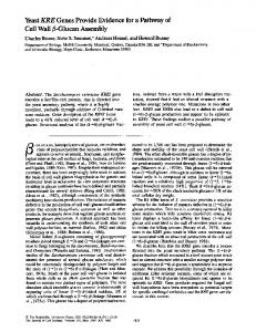
2.2 Pattern Mapping The basic idea behind our technique is that we keep the pattern unchanged during the code conversion which greatly reduces the complexity. The pattern mapping technique performs code conversion in five steps: (1) for each basic block, convert all instructions from the source DSP assembly code to the high level intermediate code; (2) copy the source's pattern to the high level intermediate code. (3) conduct pattern simplification to remove machine dependent optimization and obtain a machine independent high level intermediate code (4) convert to target machine intermediate code. (5) feed to the backend of the target machine compiler to obtain the optimized assembly code 2.3 Conversion Algorithm We now present our code conversion algorithm based on the ideas behind Pattern Mapping. (1) Given a program, find out all basic blocks and build the control flow graph. The control flow graph denotes the partial order of all basic blocks. This order is used to pick out a basic block for the following conversion. (2) For each basic block, find out all live-in registers and all live-out registers. A live-in register is the one which is written outside but read inside the basic block. A liveout register is the one which is written inside the basic block but read outside. (3) Convert the source DSP assembly instructions in this basic block into a high level intermediate code format. (4) Construct the data dependency graph for this basic block, for those basic instructions in a VLIW instruction, find out all anti-dependencies. A source node will be added to represent the entry of the basic block. If an instruction reads a variable which is written by another instruction outside the basic block, a dependency should be added between the source and this instruction. (5) Repeat steps (2) to (4) until all basic blocks are done. (6) Conduct pattern simplification to remove machine dependent optimization and latencies, and obtain a machine independent high level intermediate code. (7) Convert to target DSP intermediate code. (8) Feed into target DSP compiler to obtain the optimized assembly code. 3. Experiment To verify our approach we have conducted an experiment using the popular TIC62 as the source DSP and SC140 as the target DSP. The steps of the experiment is shown in Figure 1. We use TIC62 compiler to get TI C62 assembly code from C source code. We build DDG and the pattern, and conduct pattern simplification manually on TI C62 assembly code to get a machine
C code TIC62 compiler
TI asm code Build DDG and optimization pattern Pattern Simplification High level intermediate code Conversion Intermediate code of SC140 SC140 Compiler Backend SC140 asm code SC140 Simulator
SC140 Compiler SC140 asm code SC140 Simulator
Compare Result Figure 1 Flow Chart of Code Conversion Experiment independent high level intermediate code which is in a 3address form. After that we convert it to SC140 intermediate code manually, based on the definition of SC140 architecture and intermediate code format. We then feed this SC140 intermediate code to the backend of SC140 compiler for code generation and optimization. At last we use SC140 simulator to compare the computation result and running time of converted assembly code and the assembly code generated by SC140 compiler directly.
4. Working Example We select a dot product function as a working example. Figures 2 and 3 show its C source code and the assembly code generated by TIC6 compiler respectively. Figure 4 shows the pattern of this working example; there are three basic blocks in its control graph with the loop body in the middle. The instructions in the basic block frames denote the mapping functions.
L1:
int dotp(short a[], short b[]) { int sum; int i; sum = 0; for (i=0; i