Barrier Synchronization Pattern Rajesh K. Karmani *
[email protected]
Nicholas Chen *
[email protected]
Amin Shali *
[email protected]
Bor-Yiing Su **
[email protected]
Ralph Johnson *
[email protected]
* Computer Science Department University of Illinois at Urbana-Champaign ** EECS Department University of California, Berkeley May 11, 2009
1
Problem
How does one synchronize concurrent UEs which are mutually dependent on each other across phases of a computation?
2
Context
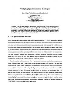
Parallel algorithms divide the work into multiple, concurrent tasks. These tasks or UEs may execute in parallel depending on the physical resources available. It is common for UEs to proceed in phases where the next phase cannot start until all UEs complete the previous phase. This is typically due to mutual dependency on the data written during the previous phase by concurrent UEs. Since UEs may execute at different speeds, there is a need for UEs to wait for one another before proceeding to the next phase. Barriers are commonly used to enforce such waiting. Figure 1 illustrates how a barrier works. A UE executes its code until it reaches a barrier. Then it waits until all other UEs have reached that barrier before proceeding. Consider the Barnes-Hut [BH86] N-body simulation algorithm. This is an iterative algorithm with well-defined phases: building the octree, calculating the forces between bodies, updating the positions and velocities of each body. One way to parallelize the algorithm is to have multiple UEs perform the three different phases. However, no UE can proceed to the next phase until all UEs complete executing the previous phase. After all, it does not make sense to update the position when some UEs are still calculating the forces between bodies. A barrier where all UEs wait for each other to reach the barrier before continuing with their respective computation, is called a global barrier. We distinguish a global barrier from another kind of barrier called local barrier, where a parent task waits for all the child tasks to finish before it can continue. 1
Figure 1 Conceptually a barrier synchronizes all UEs due to mutually dependencies across phases of a computation
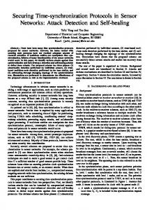
Consider the quicksort divide-and-conquer algorithm. The parent task divides the array into two and spawns child tasks to sort each half of the array. The child tasks subdivide their respective arrays into two halves and hand each half to their own child tasks and so on. A parent task must wait for both its child tasks to complete before continuing. Recursively, this argument applies to all the child tasks in the computation tree except the leaves. Conceptually, after spawning the child tasks, the parent tasks enters a barrier where it waits for all the child tasks to finish before it can use the array. Both kinds of barriers can be implemented using the other. In practice though, some problems like divide-and-conquer algorithms are naturally expressed using a local barrier, while many algorithms in scientific computing are candidates for global barriers. We provide examples and discuss usage implications in Section 6 to clarify the distinction. A variant of the barrier is an implicit barrier. An implicit barrier is typically used to synchronize UEs at the end of a code block or parallel for loop. Implementing barrier synchronization can be quite complex, and may prove to be a performance bottleneck if the programmer is not careful [HS98]. Anyhow, a barrier is an expensive synchronization mechanism since the semantics of barrier require the computation to wait for the slowest UE to arrive before the rest can proceed. Figure 2 shows how barrier synchronization can cause performance degradation by making all UEs to wait for the slowest UE. When performance is a major concern, use barriers judiciously [Tse95, SMS96].
3
Forces
Dilemma of abstraction For some programs, barrier synchronization is stronger than the synchronization needed for correct execution of the program. The programmer may still be tempted to use a barrier abstraction due to its availability in the parallel programming environment and the resulting succinctness. In such scenarios, relaxed barrier synchronization schemes such as split barrier or custom synchronization schemes such as neighborhood synchronization may perform better. Locality Locality of reference may be exploited across calls to a Barrier. This is commonly the case when barriers are used to synchronize UEs between different parallel iterations of 2
Figure 2 Barrier makes the fastest UE to wait for the slowest UE before it can proceed
a computation (See Section 6.2 for details). The placement and scheduling policy of the parallel development environment needs to be carefully reviewed in order to avoid performance degradation due to poor locality. Know thy environment Parallel programming environments like OpenMP and Cilk provide implicit barrier semantics at the end of code blocks, parallel for loops etc. Due to the two forces discussed above, it is very important for the developers to be aware of any implicit barriers in their code.
4
Solution
Use the barrier abstraction if barrier synchronization is unavoidable (for program correctness or program maintenance or shortage of time) and one is provided by the parallel programming environment. Barrier synchronization is such a common pattern in parallel and concurrent programming that it is available as an abstraction in almost all parallel programming environments. Table 1 lists the ways in which barrier abstraction can be expressed in different environments. Although the underlying architecture and the run-time placement of the UEs are important factors in the efficiency of barrier synchronization, the implementation of Barrier abstraction that is available in a programming environment can be considered to perform well for many programs. For some programs though, a barrier abstraction may succinctly express the intent of the programmer but it could be a performance bottleneck. See Section 4.1 for a discussion on implementing barrier synchronization. Relaxed barrier synchronization schemes such as split barrier, topological barrier, or custom synchronization schemes such as neighbors synchronization or pairwise synchronization could be more efficient than a full barrier and yet sufficient for correct execution of the program. The caveat is that custom synchronization code is generally hard to write, debug, understand and maintain. Deciding which barrier (local or global) to use can be quite tricky. Programs such as quicksort and other divide-and-conquer algorithms which have a tree-like task graph are naturally expressed using local barriers. On the other hand, many scientific and numerical applications, where computations proceeds in phases or iterations, are a natural fit for global barriers. Also, programs in which locality may be exploited across barriers may perform poorly, if they are implemented na¨ıvely using local barriers. 3
Environment MPI
Explicit Barrier int MPI Barrier(MPI Comm comm)
OpenMP Charm++ CUDA Cilk FJ Framework Intel’s TBB Java Thread API Java5 Concurrency API
#pragma omp barrier void contribute() syncthreads() sync keyword void join() void wait for all() and variants void join() CyclicBarrier and CountDownLatch
Implicit Barrier Some MPI Collective Communication cona structs for directive None End of kernel function End of Cilk procedure void coinvoke() void parallel for() None None
a
According to Section 4.1 of the MPI: A Message-Passing Interface Standard report (version 1.1) the presence of an implicit barrier during a collective communication call is implementation specific. For correctness and portability, a programmer should not rely on the presence of an implicit barriers. On the other hand, for efficiency, a programmer has to account for the possibility that a particular implementation includes implicit barriers for those constructs.
Table 1: Barrier abstraction in parallel programming environments Many environments also provide implicit barrier at the end of constructs such as parallel for loop or a code block. Programmers should be aware of any implicit barriers in their programs, specially given the implications of barriers on execution performance as discussed above.
4.1
Implementation
Barrier synchronization on distributed, message-passing systems such as MPI is commonly implemented using a tree-based approach [XMN92], having logarithmic cost in terms of messages and latency. On shared memory systems, the butterfly algorithm [Bro86] or its variant is commonly used. The algorithm is shown to have logarithmic scaling properties for large number of processors and avoid hot-spots associated with a tree-like approach. The butterfly approach has also been adapted to work for barrier synchronization on distributed nodes.
5
Invariants
Precondition A collection of concurrent UEs that need to be synchronized at a point in the program. Invariant A UE that reaches the barrier does not continue until all other UEs corresponding to the same barrier hit the barrier. Postcondition The blocked UEs continue their corresponding computation only after all the other UEs involved in the barrier reach the barrier point.
4
6
Examples
In this section, we present examples which show usage of different kinds of barriers i.e global, local and implicit barriers.
6.1
Quicksort with Cilk using local barrier
Listing 1 shows quicksort algorithm implemented in Cilk language [FLR98]. The program uses the built-in primitive sync for expressing a local barrier. Listing 1 Quicksort Example Using sync in Cilk 1 2 3 4
void main ( i n t [ ] A, i n t n ) { q s o r t (A, 0 , n ) ; // 0 i n c l u s i v e , n e x l u s i v e }
5 6 7 8 9
c i l k void q s o r t ( i n t [ n ] A, i n t i , i n t j ) { i f ( j −i < 2 ) return ; i n t p i v o t = A[ i ] ; // f i r s t e l e m e n t i n t p i n d e x = p a r t i t i o n (A, p i v o t , i , j ) ;
10
spawn q s o r t (A, i , p i n d e x ) ; spawn q s o r t (A, p i n d e x , j ) ;
11 12 13
sync ; // l o c a l b a r r i e r i n C i l k
14 15
// p r i n t t h e s o r t e d a r r a y }
16 17 18
}
19 20 21 22
i n t p a r t i t i o n ( i n t [ ] A, i n t p i v o t , i n t i , i n t j ) { ... }
6.2
Successive-over-relaxation in OpenMP using implicit local barrier
Successive over-relaxation is a kernel used in numerical method computation to speed up the convergence of Gauss-Seidel [Gau] method. In order to parallelize this kernel, a reordering is performed on the elements such that alternate elements can be “over-relaxed” in parallel, followed by the remaining elements. These two phases can be repeated until the desired convergence threshold is reached. This ordering is called the Red-Black ordering. Listing 2 describes successive over-relaxation in OpenMP. The grid is divided row-wise among the UEs using the parallel for directive. An implicit barrier at the end of for loop synchronizes the parallel UEs. A downside of using local barriers for synchronizing UEs across iterations or phases is that local barriers typically wait for the UEs to finish before the master UE can proceed. A new set of UEs is, hence created for the next iteration which may be placed on a processor different from the one executing the previous iteration. This results in poor locality and can hurt performance severely.
5
Listing 2 Successive over-relaxation Example Using implicit barrier in OpenMP 1
void main ( i n t [ ] [ ] A, i n t m, i n t n , i n t n I t e r a t i o n s ) {
2
f o r ( i n t i = 0 ; i < n I t e r a t i o n s ; i ++) {
3 4
// u p d a t e r e d #pragma omp p a r a l l e l f o r f o r ( i n t j = 0 ; j < m; j ++) {
5 6 7 8
f o r ( i n t k = 0 ; k < n ; k++) { i f ( ( j + k ) % 2 == 0 ) // v e r i f y i t i s r e d A[ j ] [ k ] = 0 . 2 5 ∗ (A[ j ] [ k ] + A[ j ] [ k ] + A[ j ] [ k −1] + A[ j ] [ k + 1 ] ) ; } } // i m p l i c i t b a r r i e r h e r e
9 10 11 12 13 14 15
// u p d a t e b l a c k #pragma omp p a r a l l e l f o r f o r ( i n t j = 0 ; j < m; j ++) {
16 17 18 19
f o r ( i n t k = 0 ; k < n ; k++) { i f ( ( j + k ) % 2 == 1 ) // v e r i f y i t i s b l a c k A[ j ] [ k ] = 0 . 2 5 ∗ (A[ j − 1 ] [ k ] + A[ j + 1 ] [ k ] + A[ j ] [ k −1] + A[ j ] [ k + 1 ] ) ; } } // i m p l i c i t b a r r i e r h e r e
20 21 22 23 24 25
}
26 27
}
Realizing this performance penalty, OpenMP, Intel’s TBB provide constructs for declaring affinity of UEs to processors.
6.3
Successive over-relaxation in MPI using global barrier
Alternatively, a programmer can statically map the UEs to processors in MPI, and then employ global barriers to synchronize the UEs. This preserves locality of reference across the barrier synchronization. Listing 3 shows the successive over-relaxation program written in MPI that employs a global barrier.
6.4
Successive over-relaxation using neighbor synchronization
On carefully observing the successive-over-relaxation algorithm, one can notice that the parallel UEs access the data of their neighbors only. Hence, it is sufficient to synchronize each UE with its two neighbors only. Barrier synchronization is stronger than the synchronization required for correct semantics of the successive over-relaxation algorithm. Also, barrier synchronization is expensive in terms of overhead. Therefore, when performance is a concern, programs like successiveover-relaxation are implemented using custom synchronization schemes. An implementation of successive over-relaxation in Java using neighbor synchronization can be found in Java Grande Benchmarks [SBO01]. As discussed earlier, custom synchronization code is generally hard to write,
6
Listing 3 Successive over-relaxation Example Using a global barrier in MPI 8
i n t main ( i n t argc , char∗ argv [ ] ) {
9
i n t my id ; int n u m b e r o f p r o c e s s o r s ;
10 11 12
// SOR w i t h row−w i s e a g g l o m e r a t i o n // // I n i t i a l i z e MPI and s e t up SPMD programs // M P I I n i t (& argc ,& argv ) ; MPI Comm rank (MPI COMM WORLD, &my id ) ; MPI Comm size (MPI COMM WORLD, &n u m b e r o f p r o c e s s o r s ) ;
13 14 15 16 17 18 19 20
i f ( my id == MASTER NODE) { // b r o a d c a s t A t o t h e s l a v e nodes } e l s e { // s l a v e nodes perform t h e SOR c o m p u t a t i o n
21 22 23 24 25
// r e c e i v e t h e b r o a d c a s t c o n t a i n i n g A from t h e master node
26 27
f o r ( i n t i = 0 ; i < ITERATIONS ; i ++) { // u p d a t e r e d f o r ( i n t k = 1 ; k < n ; k++) { i f ( ( my id + k ) % 2 == 0 ) // v e r i f y i t i s r e d A[ my id ] [ k ] = 0 . 2 5 ∗ (A[ my id ] [ k ] + A[ my id ] [ k ] + A[ my id ] [ k −1] + A[ my id ] [ k + 1 ] ) ; }
28 29 30 31 32 33 34 35
MPI BARRIER(MPI COMM WORLD) ;
36 37
// u p d a t e b l a c k f o r ( i n t k = 1 ; k < n ; k++) { i f ( ( my id + k ) % 2 == 1 ) // v e r i f y i t i s b l a c k A[ my id ] [ k ] = 0 . 2 5 ∗ (A[ my id ] [ k ] + A[ my id ] [ k ] + A[ my id ] [ k −1] + A[ my id ] [ k + 1 ] ) ; } MPI BARRIER(MPI COMM WORLD) ; }
38 39 40 41 42 43 44 45
}
46 47
MPI Finalize ( ) ; return 0 ;
48 49 50
}
debug, understand and maintain.
6.5
Conway’s Game of Life in CUDA using implicit global barrier
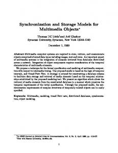
Conway’s game of life is a cellular automaton first proposed by the British mathematician John Horton Conway in 1970. The game is a simulation on a two-dimensional grid of cells. Each cell starts off as either alive or dead. The state of the cell changes depending on the state of its each
7
neighbors in the grid. At each time-step, we update the state of each cell according to the following four rules. 1. A live cell with fewer than two live neighbors dies due to underpopulation. 2. A live cell with more than three live neighbors dies due to overpopulation. 3. A live cell with two or three live neighbors survives to the next generation. 4. A dead cell with exactly three live neighbors becomes a live cell due to breeding. Figure 3 shows an example of the Conway’s Game of Life. The example starts with a cross and evolves through two time steps. Listing 4 shows a parallel implementation of the game of life in CUDA. The program generates threads equal to the number of cells, and updates the status of each cell independently. Listing 5 shows how we update the status of each grid. Before proceeding to the next time step, it is necessary that all the grids have been updated. This requirement can be ensured by using a global barrier for all threads. CUDA provides an implicit global barrier at the end of execution of each kernel function as shown in listing 4. Figure 3 2 time steps of a life game starting with the topology of a cross
7
Known Uses
SIMD computations proceed in lock-step fashion and therefore, have an implicit barrier.
8
Related Patterns
Collective Synchronization Barrier provides a way for synchronizing a set of UEs. It is a basic pattern for the Collective Synchronization [OPL] pattern. Reduction In some parallel programming environments such as Charm++ [Cha], the Reduction abstraction is used with a NULL operator to effectively behave as a Barrier. Rendezvous A Rendezvous is a special case of barrier synchronization in which only two UEs are involved. This distinction is sometimes not rigidly observed. 8
Listing 4 Routine for Game of Life simulation 42 43 44 45 46
void GameOfLife ( i n t t i m e P e r i o d , i n t width , i n t h e i g h t , i n t ∗ devInputArray , i n t ∗ devOutputArray ) { dim3 blockDim (BLOCKX, BLOCKY) ; dim3 gridDim ( ( width+BLOCKX − 1 ) /BLOCKX, ( h e i g h t+BLOCKY− 1 ) /BLOCKY) ;
47
f o r ( i n t i = 0 ; i < t i m e P e r i o d ; i ++) { UpdateStatus(width , h e i g h t , devOutputArray ) ; // I m p l i c i t G l o b a l B a r r i e r Here . cudaMemcpy ( devInputArray , devOutputArray , s i z e o f ( i n t ) ∗ width ∗ h e i g h t , cudaMemcpyDeviceToDevice ) ; }
48 49 50 51 52 53 54 55
}
Listing 5 Routine for updating the status of a grid global
13 14
void UpdateStatus ( i n t width , i n t h e i g h t , i n t ∗ devArrayOutput )
{ i n t x = IMUL( blockDim . x , b l o c k I d x . x ) + t h r e a d I d x . x ; i n t y = IMUL( blockDim . y , b l o c k I d x . y ) + t h r e a d I d x . y ; i n t i d = y∗ width+x ; i n t count = 0 ; f o r ( i n t i = −1; i < 2 ; i ++) { f o r ( i n t j = −1; j < 2 ; j ++) { i n t xnext = x + i ; i n t ynext = y + j ; i f ( ( xnext >= 0 && xnext = 0 && ynext