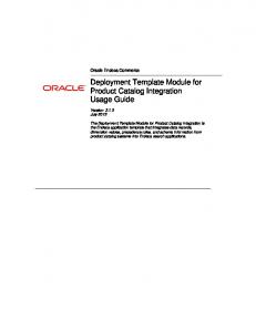
155
Assistive tools for system integration, deployment, monitoring, and maintenance of ocean energy devices E Omerdic1*, D Toal1, and M Leahy2 1 CPI on Energy & Sustainable Environment, Department of Electronic and Computer Engineering, University of Limerick, Limerick, Ireland 2 CPI on Energy & Sustainable Environment, Department of Physics, University of Limerick, Limerick, Ireland The manuscript was received on 5 February 2010 and was accepted after revision for publication on 9 April 2010. DOI: 10.1243/14750902JEME210
Abstract: This paper describes a set of assistive tools and technologies for system integration, deployment, monitoring, and maintenance of ocean energy devices. The flexible design of these tools enables their use as separate standalone modules, as well as their integration into a unique integrated system. A major component of the system is a smart remotely operated vehicle ROVLATIS – a novel, multi-mode of operation marine robotics vehicle designed for flexibility in near seabed operations from shallow inshore waters out to the continental shelf edge. Ocean energy technologies play an important part in meeting the Irish government’s energy strategy, which targets 33 per cent of Irish electricity to be generated from renewable sources by 2020. The assistive tools, proposed in this paper, will help developers of ocean energy devices in meeting this target during different stages of design, deployment, and operation. Keywords: smart ROV, ocean energy, fault-tolerant control, control allocation, real-time visualization, augmented reality 1 1.1
INTRODUCTION Background
Medium and long-term trends in the cost of fossil fuels are upwards. At the same time, use of fossil fuels as energy sources has a negative impact on the environment. Ireland has a vast range of highpotential renewable energy resources. For example, theoretical and accessible levels of wave energy resources in Irish waters, estimated by Sustainable Energy Ireland (SEI) [1], are 525 TWh per annum and 21 TWh per annum respectively, while the overall electricity demand in Ireland for 2006 was estimated at 27.8 TWh. In another study, SEI [2] estimated viable levels of tidal energy resources in Ireland to be approximately 0.915 TWh per year, considering only areas with tidal stream velocities of 2 m/s or higher, owing to current technology limitations. Wind is expected to play a dominant role in meeting the target of 33 per cent of electricity from renewables [3]. After the saturation of financially attrac-
*Corresponding author: Department of Electronic and Computer Engineering, University of Limerick, Limerick, Ireland. email:
[email protected] JEME210
tive wind sites and improvements in the technology, ocean energy will make an important contribution. Ocean energy resources, the main topic of the following discussion, include wave and tidal energy.
1.2
Wave energy
Differential solar heating of the earth generates wind, which travels over vast volumes of ocean water transferring energy to the water to produce waves. Wave energy devices use various conversion technologies to generate electric energy from mechanical energy stored in the waves. These conversion technologies make use of fluid pressure or mechanical motion to generate electricity. The most common techniques include linear electric generators, hydraulic devices, elastomeric hose pumps, pump to shore, and air/hydro-electric conversion turbines. The type of device used depends on the location, which can be offshore, nearshore, and onshore. There are important device types [4, 5]. 1. Overtopping devices: an artificial basin is filled with water such that waves flow over a sloped barrier. Then the detained water is piped through a turbine to generate electricity.
Proc. IMechE Vol. 224 Part M: J. Engineering for the Maritime Environment
156
E Omerdic, D Toal, and M Leahy
2. Oscillating water column: one side of the device is in water. Waves cause rise of water in the column, which cause the displacement of air. The air flows through an air turbine, placed at the open end of the device, to produce electricity [6]. 3. Point absorbers: a buoy is used to convert mechanical energy of waves to electric power (using linear/rotational motion of a generator armature relative to stator) or hydraulic power. For examples, see references [7] and [8]. The major wave energy device developers in Ireland are Ocean Energy Ltd (Backward Bent Duct), Wavebob Ltd (Wavebob) and Hydam Ltd (McCabe Wave Pump). After success in the initial testing of small-scale prototypes, these developers are engaged in a process of constructing full-scale models of their devices. The target date for commercial deployment of wave devices in Ireland is 2016 [2].
1.3
Tidal energy
Energy from ocean tides can be used to produce electricity. Devices designed to operate in the tidal stream or current utilize the kinetic energy, while the rise and fall of tide installations utilize the potential energy. Tidal energy originates from the relative motions of the earth, moon, and sun. There are two main types of tidal energy device [4]. 1. Tidal barrages: these devices make use of potential energy from the difference in head between high and low tides. They can operate using ebb generation and flood generation, and as double basin or two-way generation systems. 2. Tidal stream devices: these devices make use of kinetic energy from the moving water to drive a turbine, similar to wind turbines. Owing to significant cost savings compared to tidal barrages, this technology is becoming a popular direction for generating electricity from renewable sources. The major tidal energy device developer in Ireland is OpenHydro, which recently completed the connection of a 250 kW tidal turbine to the UK national grid [9] and deployment of a 1 MW commercial tidal turbine in the Bay of Fundy [10].
1.4
Obstacles
The major obstacles restricting the development of wave and tidal energy devices are [4]:
(a) technologies are in the development phase, with little demonstration experience; (b) ocean energy devices must be capable of withstanding extremely harsh weather conditions, which add to the cost of design and material; (c) deployment and maintenance costs may be relatively high because of locations where ocean devices are deployed; (d) unknown environmental issues associated with power generation from wave and tidal energy; (e) non-uniform grid connection and access (in most cases best locations for technology development and deployment usually have poor grid capacity and access); (f) the taxes on renewable energy technologies reduce the competitiveness of the technology; (g) the cost of entry to commercially viable wavefarm demonstration is likely to be of the order of J100 million, which represents a substantial hurdle. 1.5
Rationale
This paper proposes a set of aiding tools and technologies that will address some of the issues identified in section 1.4 and provide a framework for better planning, deployment, real-time monitoring, and maintenance of ocean energy devices. The vision of the future for ocean energy devices [11] sees the complexity and costs of many of the systems deployed in the oceans increasing with time. With significant increase in costs and technical complexity, it becomes of paramount importance to carry out as much engineering development, system testing, and scenario ‘what-if’ analysis in the design phase of these complex systems rather than in the roll-out, deployment, and operational phases. This will require the development of virtual ocean simulation environments and significant hardware-in-the-loop testing. For example, complete virtual reality simulation of the ocean energy devices, surface support vessels, remotely operated vehicles (ROVs), power connections, data transmission, and physical characteristics can provide a virtual test bed prior to field deployment with associated cost benefits. Many integration problems could be detected, isolated, and resolved in advance, yielding significant costs savings and improving the reliability of the overall system. In addition, the same test bed could be used to support enhanced real-time visualizations during deployment and maintenance operations. At present, the typical displays presented to ROV operators during deployment and maintenance operations with ocean energy devices include low-
Proc. IMechE Vol. 224 Part M: J. Engineering for the Maritime Environment
JEME210
System integration, deployment, monitoring, and maintenance of ocean energy devices
visibility real-time images from on-board cameras and optional two-dimensional (2D) situation top view display(s). During such operations, the ROV is subject to disturbances, such as strong currents and waves. The assistive visualization and control tools, proposed in this paper, provide operators with better situation awareness and enhanced vehicle control in the presence of disturbances, allowing them to concentrate on the task and to complete the work in a satisfactory manner and in a shorter time. The direct benefits of this approach are reduced maintenance and deployment costs owing to savings in expensive support vessel time.
1.6
Research activities in the CPI Mobile and Marine Robotics Research Centre
Over the last five years, researchers in the Mobile and Marine Robotics Research Centre (MMRRC) at the University of Limerick have been engaged in collaborative science and engineering-led seabed survey projects, including technical-design, integration, and offshore support [12, 13] and survey operations carrying out detailed survey projects acquiring high-resolution bathymetric, sidescan, and video imagery/maps. The team has further developed a real-time virtual underwater laboratory (VUL) [14] and real-time high-resolution sidescan sonar simulators [15] for use in laboratory testing, training, and offshore operations support. The idea to integrate all these technologies into a unique system (multipurpose platform technologies (MPPT) ring) has been proposed in reference [16]. Based on the experiences gained in these projects, the challenges met, the solutions developed and confirmed in a simulation environment, and the inherently high costs associated with marine technology and offshore operations, the MMRRC decided to develop a flexible multimode of operation survey class thrusted pontoon/ ROV, which serves as a platform to test system validity and viability. The MMRRC has focused on research in a number of areas, including autonomous underwater vehicle (AUV)/ROV systems integration, embedded controller development, sensor systems development, and in the modelling and real-time simulation of AUV/ ROV dynamics and acoustic payload instruments since 2000. Scientific sponsored zoological surveys, such as deep ocean habitat mapping and commercial geo-referenced acoustic mapping of shipwrecks, are among ancillary activities conducted by this research centre. A new remote sensor deployment platform was required to meet the immediate (shallow JEME210
157
water) survey needs of the MMRRC and to provide a flexible test bed for research in vehicle and control system development and in sensor systems going forwards. The design of this new vehicle was motivated in part by practical difficulties and predicaments encountered in pre-survey instrument system design/ integration and during inshore and offshore survey work with leased ROV sensor platforms. Key design requirements for the new platform included: (a) it should be able to support the core survey suite, including the multi-beam, sidescan, inertial navigation system (INS), Doppler velocity log (DVL), pressure (depth) sensor and ultrashort base line (USBL) transponder; (b) it should accommodate both subsea survey activities and wide area (surface) survey activities in order to maximize equipment utility; (c) it should be deployable using small surface support vessels, such as tugs, trawlers, etc., thus reducing operational costs for inshore work; it should also be suited to operations from larger survey vessels for off-shore work. Control design requirements included the following: (a) it should have built-in auto-tuning features for low-level controllers; (b) it should be able to detect, isolate, and accommodate thruster faults; (c) it should be able to work in fully automatic mode, i.e. automatic way-points navigation; (d) it should be able to keep the desired position and orientation deeply submerged in the water (dynamic positioning (DP)), in the presence ofocean currents. To meet these objectives a hybrid ROV/thrustedPontoon vehicle, ROVLATIS, has been designed built and tested. A full description of ROVLATIS can be found in references [17] and [18].
1.7
Paper outline
An overview of the proposed system is given in section 2. The system components are described in section 3. Selected results of test trials are presented in section 4. Possible system applications in the field of ocean energy development are given in section 5. Finally, section 6 summarizes the concluding remarks and provides directions for future work.
Proc. IMechE Vol. 224 Part M: J. Engineering for the Maritime Environment
158
2
E Omerdic, D Toal, and M Leahy
SYSTEM OVERVIEW
The assistive tools and technologies are integrated into a system called the VUL for ocean systems modelling and simulation (Fig. 1). The system core is built from a set of tools (simulation tools, modelling tools, control tools, and visualization tools), which provide easy and transparent interfaces between the real-world environment and the virtual environment. The real-world environment consists of the following real-world components: (a) real ocean energy devices: wave energy point absorbers, tidal stream devices, etc.; (b) real ROVs: used for the survey, deployment, and maintenance of ocean energy devices; (c) real support vessels: ships, boats etc., used as support platforms for launching/recovery of ROVs. In the real-world environment, each real-world component is subject to real-world disturbances (real waves and real ocean currents). Each real-world component has the equivalent virtual component in the virtual environment. A virtual component is a mixed hardware/software real-time dynamic system, which is fully input–output compatible with a corresponding real-world component on a signal level (Fig. 2). This means, for example, that the output message with navigation data for the virtual ROV is sent through the serial ports in the same format as the output of the real INS installed on the ROV (identical message formats including checksums; identical RS232 port settings including baud rate, parity, number of stop bits, etc.). In this way the real-time controllers do not know the data source, i.e. if data are coming from the real-world or virtual instruments. This transparency of data sources, together with hardware-in-the-loop (HIL)
Fig. 1
control devices set-up, provides a unique framework to design, develop, and test the control system before the actual physical system components, such as ROV or ocean energy device, are built. Software switches S1, S2, and S3 inside the system core are used to select the source of navigation and measurement data for a support vessel, ROV, and ocean energy device (Fig. 3). Depending on the position of switches S1, S2, and S3, eight application modes can be distinguished, as illustrated in Fig. 4. Mode A was used during the ROVLATIS development stage. Mode C was used when the physical work on the ROV was completed, but the support vessel (ship) was not yet available. An interesting example of Mode E application is a pre-mission practice with the virtual ROV in a real-world environment (see section 4.1). Mode G was used during the real-world tests with the real ROV, real support vessel, and virtual ocean energy device(s). Finally, mode H could be used when real ocean energy devices become available. In addition to input–output compatibility (electrical interface), there is also visual compatibility between real-world and corresponding virtual components, i.e. each real-world component is represented in virtual reality as a virtual model, with the same physical dimension and appearance (same colour, etc.). Each virtual component is subject to virtual disturbances (virtual waves and virtual ocean currents). More information about virtual disturbances can be found in section 3.2. 3 3.1
SYSTEM COMPONENTS Real-world environment
To date, the MMRRC team deployed the ROVLATIS from the Celtic Explorer (Marine Institute) and
Virtual underwater lab for ocean systems modelling and simulation
Proc. IMechE Vol. 224 Part M: J. Engineering for the Maritime Environment
JEME210
System integration, deployment, monitoring, and maintenance of ocean energy devices
Fig. 2
159
Real ROV and virtual ROV: input–output compatibility on a signal level
Fig. 3 Source selection for system data JEME210
Proc. IMechE Vol. 224 Part M: J. Engineering for the Maritime Environment
160
E Omerdic, D Toal, and M Leahy
Fig. 4
Application modes (possible settings of switches S1, S2, and S3)
Shannon One Multi-Cat (Shannon Port Company) research vessels (see Figs 5 to 7). Network and serial interfaces have been developed for direct connections with navigation equipment on these support vessels. The existing library can be easily expanded to interface the system core with other support vessels, such as RV Celtic Voyager or similar. As mentioned in sections 1.2 and 1.3, potential real-world ocean energy devices could be smallscale/full-scale prototypes, for example the Back-
ward Bent Duct (Ocean Energy Ltd), Wavebob (Wavebob Ltd), McCabe Wave Pump (Hydam Ltd), or a tidal stream turbine (OpenHydro) (Fig. 8). 3.2
Virtual environment
Full virtual models of ROVLATIS, Celtic Explorer, and the Shannon One Multi-Cat have already been developed and validated during test trials in Galway Bay (March 2009) and Limerick Dock (July 2009).
Fig. 5 Support vessel Celtic Explorer Proc. IMechE Vol. 224 Part M: J. Engineering for the Maritime Environment
JEME210
System integration, deployment, monitoring, and maintenance of ocean energy devices
Fig. 6
Support vessel Shannon One Multi-Cat
Fig. 7
Development of virtual components of ocean energy devices is work in progress. For demonstration purposes virtual generic tidal stream turbines are used in the following sections (Fig. 9). Real-time models of ocean dynamics are very useful for the design, development, testing, and validation of marine technology in simulation. Many models of waves and currents are proposed in the literature, ranging from very simple to very complex models. In order to accommodate these models for real-time simulation of ocean dynamics, a balance needs to be achieved between complexity of the model and constraints imposed by the requirement for synchronization with real-time. Models of virtual waves and virtual ocean currents, implemented as JEME210
161
ROVLATIS
part of the virtual environment inside the VUL for ocean systems modelling and simulation, are simple enough to fulfil real-time requirements, while general enough to describe most phenomena of interest. A full description of wave and ocean current models, used as virtual disturbances, is given in reference [19].
3.3
System core
The system core consists of hardware and software modules integrated into the control centre. The control centre can be located on a support vessel (for example, the control cabin – see Fig. 10) or onshore. Since the ethernet network is used as the main communication
Proc. IMechE Vol. 224 Part M: J. Engineering for the Maritime Environment
162
E Omerdic, D Toal, and M Leahy
Fig. 8
Real-world renewable ocean energy devices
medium, it is easy to expand the system by adding more monitoring points through the internet. The development of the overall system has been implemented using a ‘V diagram’ product development cycle, based on rapid control prototyping (RCP) and HIL techniques, in order to make this cycle as efficient as possible. Software tools used for system development (LabVIEW, Matlab, and Visual Studio C++) offer a variety of advanced modelling, simulation, control design, and visualization tools in an interactive environment that helps the designer to quickly evaluate a system without the need for prototype hardware. This capability provides the ability to determine specification, requirements, and modelling errors immediately instead of waiting for testing later in the design flow. Data outputs of individual components are bundled into clusters and transmitted using network-published shared variables,
based on the NI publish–subscribe protocol (NI-PSP). The NI-PSP protocol uses less network bandwidth and is more efficient than TCP/IP for the given requirements of the NI-PSP protocol. Unlike the user datagram protocol (UDP) however, the NI-PSP protocol guarantees delivery by implementing an additional layer of functionality on top of the raw UDP protocol. To support mission planning, rehearsal, mobilization, sea operations, and ROV pilot and operator/ hydrographer training, the MMRRC has developed a suite of innovative hardware and software tools, which can be used stand-alone or as part of a fully integrated ROV survey operation system. The tools include: pulse RT, MPPT ring, and adaptive multisonar controller. A full description of these tools can be found in references [15] to [17] and [20]. The main features of these tools include:
Proc. IMechE Vol. 224 Part M: J. Engineering for the Maritime Environment
JEME210
System integration, deployment, monitoring, and maintenance of ocean energy devices
163
(b) an advanced and flexible fault-tolerant ROV control system with auto-tuning and dynamic positioning capabilities; (c) survey planning and operation tools; (d) signal-level input–output compatibility between virtual and real-world environments; (e) improved survey planning and execution with optimized ground coverage; (f) on-the-fly generation of the digital terrain model.
3.4
Fig. 9 Virtual generic tidal stream turbines
(a) three-dimensional (3D) real-time visualization of the support vessel, ROV, ocean energy device, ocean surface, seabed, etc.;
Fig. 10 JEME210
ROV fault-tolerant control system
The ROVLATIS control system utilizes the control allocation approach, where the actuator selection task (mapping of the total control efforts onto individual actuator settings) is separated from the regulation task (design of total control efforts) in the control design. A hybrid approach for control allocation [21] is based on the integration of the pseudoinverse and the fixed-point iteration methods. It is implemented as a two-step process. The pseudoinverse solution is found in the first step. Then the feasibility of the solution is examined analysing its individual components. If violation of the actuator constraint(s) is detected, the fixed-point
Look inside the control cabin Proc. IMechE Vol. 224 Part M: J. Engineering for the Maritime Environment
164
E Omerdic, D Toal, and M Leahy
iteration method is activated in the second step. In this way, the hybrid approach is able to allocate the exact solution, optimal in the l2 sense, inside the entire attainable command set. This solution minimizes a control energy cost function, the most suitable criterion for underwater applications. A hybrid control allocation approach is implemented inside the LabVIEW Universal Control Allocation Express VI (Fig. 11). All inputs to the universal control allocation Express VI are normalized to standard intervals. Depending on user-defined settings, the outputs (actuator settings) can be compensated for non-symmetrical propeller thrust–speed curves and adapted (scaled and/or rounded, if necessary) to meet the requirements of thruster input interfaces. The degree of usage of each thruster is controlled by sliders HT (VT) saturation bounds. The position of these sliders is determined by the ROV pilot or fault
accommodation system, depending on the state of thrusters (healthy, partial fault, or total fault). For a healthy thruster, its slider value should be set to 1. For a total faulty thruster, the slider value should be set to 0. Finally, the slider value should be set between 0 and 1 for a thruster with partial fault.
4
SYSTEM VALIDATION
The performance of the overall system has been successfully validated through a series of test trials in Galway Bay and Limerick Dock.
4.1
Galway Bay
Offshore trials (survey cruise; CE-09-04) of ROVLATIS were undertaken off the west of Ireland’s Conne-
Fig. 11 Universal control allocation express VI: basic inputs and outputs Proc. IMechE Vol. 224 Part M: J. Engineering for the Maritime Environment
JEME210
System integration, deployment, monitoring, and maintenance of ocean energy devices
mara coastline from 26 February to 6 March 2009. The cruise was a multi-purpose engineering and science mission (ROV testing, sonar controller testing, sensor platform testing seabed mapping, vibro core, and bottom grab sampling) with 18 researchers (scientists and engineers) and D. Toal as chief scientist. The vehicle was mobilized using the ship RV Celtic Explorer. The cruise consisted of a day in Galway port integrating and testing ROV and ship interfaces and six days at sea. During the trials all of the ROV’s systems were proved, sensor interoperability was demonstrated, and comprehensive vehicle diagnostics were performed. In addition, system identification was performed on the ROV and the tuning of vehicle controllers was successfully carried out. A series of pre-planned survey missions were also conducted. These missions were used to trial
Fig. 12
JEME210
165
the operation of the vehicle, the MPPT ring, the ROVs augmented reality topside control and visualization, the adaptive multi-sonar controller, and the use of vision systems for near seabed navigation. Selected survey results are reported here. 4.1.1
High-resolution site survey near Aran Islands
An unexpected scientific discovery arose on the CE09-04 cruise. An area of rock north east of Inis Iarr in the Aran Islands was chosen to perform a number of experiments, including ROV ops near seabed survey scenario assessment. The ROVLATIS was deployed in close proximity to the seabed, allowing for the acquisition of high-resolution multi-beam and sidescan sonar datasets. Figure 12 illustrates real-time monitoring of the ROV position relative to the sup-
3D real-time augmented reality display: better situation awareness during multi-beam and sidescan transects Proc. IMechE Vol. 224 Part M: J. Engineering for the Maritime Environment
166
E Omerdic, D Toal, and M Leahy
port vessel during multi-beam and sidescan transects using MPPT ring augmented reality displays. An adaptive multi-sonar controller (patent pending) [20] was used for adaptive ping scheduling of the Reson 7125 high-resolution multi-beam, Tritech – AUV sidescan sonar, and RDI DVL WorkHorse, which operated simultaneously without the effects of crosssensor acoustic interference. The acquired datasets showed never-before-seen detail ripple beds of mearl – previous bathymetric surveys of the area with a hullmounted multi-beam were unable to provide such detail. The simultaneous sidescan sonar data also provided valuable complementary information about the beds. Figure 13 shows a sample of the bathymetry data, collected during the cruise, laid on top of previously acquired data. Because of this discovery, the area is of great interest to marine researchers and warrants greater investigation.
4.1.2
Pre-mission practice with virtual ROV and real support vessel
The support vessel arrived on location in Galway Bay to perform vision experiments. Prior to deployment of the real ROV, mixed-mode E was activated (switch S1 in position real-world environment and switches S2 and S3 in position virtual environment, see Figs 3 and 4). In other words, the ship motion in the 3D real-time augmented reality display was real, while the ROV motion was simulated, i.e. while the real ROV was located on the deck, the virtual ROV was
placed in the water and controlled by joystick. In this way the ROV pilot was able to practise the requirements imposed by mission objectives with the virtual ROV in a realistic environment, including diving to the desired depth, following a figure of eight trajectory etc. (see Fig. 14). The day after practising, switch S1 was switched to a real-world environment position, the real ROV was deployed in the water, and the vision experiments were realized without any trouble in a very satisfactory and smooth way. A number of missions were successfully completed by the end of cruise, including a night inspection of a weather buoy near a wave energy test site in Galway Bay, automatic way-point navigation, auto-tuning of low-level controllers, etc.
4.2
Limerick Dock launch and trials
Demo trials of ROVLATIS were undertaken in Limerick Dock in the period 1–3 July 2009. The trials included an official launching ceremony, diving, wall and gate video inspection, full multi-beam and sidescan survey of the gate zone of the dock, testing of the thruster fault-tolerant control system, etc. Selected trial results are reported here. The level of ROV pilot situation awareness during operations and rehearsals was significantly improved through the usage of the 3D real-time augmented reality display. A realistic virtual reality (VR) model of Limerick Dock was built during the presurvey preparation phase in three steps (see Fig. 15). Step 1: The top view image of Limerick Dock was obtained in Google Earth. Step 2: The top view image was imported to Sketchup Pro, transformed to a simple 3D model and exported in virtual reality modelling language (VRML) format. Step 3: A full 3D VRML model of Limerick Dock was built, including the ROV model, water surface, sky, etc.
Fig. 13
High-resolution bathymetry data acquired with ROVLATIS overlaid on lower resolution data from Irish National Seabed survey
A comparison of real and virtual camera views is shown in Fig. 16. The view from the real onboard pilot camera is shown in the top left monitor, while the corresponding view from the virtual pilot camera is shown in the top right monitor. The picture was taken between two missions, while the vehicle was on the deck. Owing to independent open-loop operator tilt control of real and virtual cameras, a small difference in elevation can be observed, since the real camera was slightly tilted down, while the virtual camera was not tilted at all. Figure 17 is taken during a full sonar and video survey of the zone near the gate. High-resolution
Proc. IMechE Vol. 224 Part M: J. Engineering for the Maritime Environment
JEME210
System integration, deployment, monitoring, and maintenance of ocean energy devices
Fig. 14
167
3D real-time augmented reality display: pre-mission practice with virtual ROV in realistic environment (mixed-mode E)
Fig. 15 Limerick Dock virtual reality model: building stages JEME210
Proc. IMechE Vol. 224 Part M: J. Engineering for the Maritime Environment
168
E Omerdic, D Toal, and M Leahy
Fig. 16
Control cabin: comparison of views from real and virtual pilot cameras
Fig. 17
Gate and wall inspection
multi-beam and video data have been collected, showing valuable information of mud distribution and water depth inside the zone near the gate.
4.2.1
Evaluation of fault-tolerant features
In order to test the performance of a fault-tolerant control system, a number of test trials were performed in Limerick Dock. The main task imposed on the ROV control system was the path following with faulty thruster. The path was defined with a set of waypoints. Different faulty situations were artificially generated by changing values of HT/VT sliders in Fig. 11. Figure 18 shows the results from one of these tests. In this particular case, the front left horizontal thruster was disabled and the ROV was commanded to follow the rectangular path defined by way points WP1–WP4 in surface mode of operation, with a constant forward speed of 0.4 m/s. As indicated in Fig. 18, an excellent tracking performance was achieved with only three working horizontal thrusters.
4.2.2
Real-time monitoring and maintenance of ocean energy devices (virtual environment)
In the following example, virtual generic tidal stream devices were placed on the seabed and the typical maintenance mission was simulated with a virtual ROV and a virtual support vessel (application mode is mode A in Fig. 4). Simulated measurement and navigation data were processed with the system core and used for real-time control and visualization purposes. The mission objective was to simulate vehicle deployment, diving and inspection/maintenance under harsh conditions (strong waves and currents). Different sea states were simulated, with the International Towing Tank Conference (ITTC), joint North Sea wave project (JONSWAP), and Torsethaugen spectrum types, different numbers of wave directions (short-crested and long-crested waves), etc. Ocean currents were simulated as a layered timevarying 3D vector field, with different dominant directions in each layer. In all cases the control system was capable of performing given control tasks, such as
Proc. IMechE Vol. 224 Part M: J. Engineering for the Maritime Environment
JEME210
System integration, deployment, monitoring, and maintenance of ocean energy devices
169
Fig. 18 3D real-time augmented reality display: path following with faulty horizontal thrusters
keeping a given position and orientation, going to a given position, etc. Different stages of a mission are indicated in Fig. 19, including dynamic positioning of the ROV on the surface in the presence of waves and currents, diving, dynamic positioning in close proximity to the ocean turbines, and viewing of the underwater scene from different view points with low and high visibility (a feature useful in training pilots). 5
POSSIBLE SYSTEM APPLICATIONS
Possible applications of the VUL for ocean systems modelling and simulation in the field of ocean energy development include the following. Planning 1. Building of complex underwater scenarios using an expandable database of objects (ocean energy devices, ROVs and support vessel models), structures, custom components (moorings, buoys, etc.). 2. Performing detailed high-resolution sonar and video survey of possible site locations. 3. Generation of marketing ‘proof of concept’ visualizations, 4. Simulation of run-time behaviour in normal and critical situations under disturbances (waves, currents) using full 6 degree of freedom (DOF) real-time simulators, with and without partial faults in the plant. JEME210
Integration 1. Performing tests for the system as a whole while simulating some of the equipment. 2. Verification of connections and interfaces between individual pieces of equipment and verification of full connectivity, inter-operability, and calibration before mobilization. 3. Enabling faster connection with ocean energy devices, support vessel, and ROV resources. Deployment and real-time monitoring during construction and maintenance operations offshore 1. Expansion or enhancement of existing operator displays (pilot camera with low visibility) with 3D real-time augmented reality displays. 2. Choice and control of virtual view points to see system components from any angle or vantage point. 3. Better situation awareness. 4. Elimination of decision uncertainties due to bad visibility/harsh weather, etc.
Ocean energy installation routine system operation 1. System state information, operation displays, and alarms during plant operation relayed to com-
Proc. IMechE Vol. 224 Part M: J. Engineering for the Maritime Environment
170
E Omerdic, D Toal, and M Leahy
Fig. 19 3D real-time visualization of typical maintenance mission in virtual environment
mand control with real-time augmented reality displays of ocean deployed plant and conventional control switchboard display information. 2. Display of monitored electrical plant parameters; generator line and phase voltages voltage, current frequency, power factor, instantaneous power, status indications from electrical protection and control switchgear, contactors, power electronics status, temperatures in enclosures, leak detection, etc. 3. Display of monitored mechanical plant parameters; revolutions per minute (RPM) for rotating machinery or speed and stroke for linear machines, tension in buoy tethers, and foundation stays, mechanical, thrust load on bearings, out-of-balance forces, mechanical system alarms, bearings, gearboxes, etc.
4. Display of monitored environmental parameters; current flow, direction, wave parameters, height, frequency, spectral information, wind speed, weather forecast, wind, tidal flow, and wave predictions, etc.
In the field maintenance of ocean energy installations 1. Pre-mission practice with systems part virtual and part real-world (e.g. virtual ROV flying on real energy plant in real-world environment). 2. Possibility to create normal and critical situations (very strong waves and currents) and practice in the safe virtual environment, before actual mission execution.
Proc. IMechE Vol. 224 Part M: J. Engineering for the Maritime Environment
JEME210
System integration, deployment, monitoring, and maintenance of ocean energy devices
3. Control and visualization tools allow operators to concentrate on the task in hand and complete it in a satisfactory manner. 4. Log run-time data for later replay and analysis.
Offline analysis 1. Replay of mission/operation looking at the scenario from any angle/viewpoint. 2. Determine factors that need to be improved for future missions.
6
CONCLUSIONS AND FUTURE WORK
This paper has presented a set of assistive tools and technologies for system integration, deployment, monitoring, and maintenance of ocean energy devices. These tools are integrated into a system called the VUL for ocean systems modelling and simulation. The main components of the system are: the system core, the real-world environment, and the simulation environment. Input–output compatibility between the real-world and virtual components enables easy switching between environments, creating opportunity for a variety of applications. Many integration problems can be detected, isolated, and resolved in advance. Different mission scenarios can be designed and verified through the mixed use of virtual and real-world components, yielding significant costs savings and improving the reliability of the overall system. Development of the VUL for ocean systems modelling and simulation is work in progress. Future work will include the full development of virtual models of ocean energy devices, including real-time simulators of mechanical and electrical subsystems, development of interconnection interfaces compatible with the realworld devices, etc. However, since ocean energy technology development is still in early and pre-commercial stages, it is expected that there may be some difficulty in obtaining full descriptions of device interfaces for reasons of intellectual property protection and such as trade secrets, knowhow, etc.
ACKNOWLEDGEMENTS The development of ROVLATIS and of the modelling and operations support tools described has been supported by funding under the Irish Marine Institute and the Marine Research, Technology JEME210
171
Development and Innovation (RTDI) Measure, Productive Sector Operational Programme, National Development Plan 2000–2006 (PhD -05-004, INF06-013 and IND-05-03); Science Foundation Ireland under grant number 06/CP/E007 (Charles Parsons Energy Research Awards 2006); Higher Education Authority (HEA) Programme for Research in ThirdLevel Institutions (PRTLI) 3 (MSR3.2 project – Deep Ocean Habitat Mapping using and ROV; HEA PRTLI 4 Environment and Climate Change Impacts and Responses Project/ Environment Graduate Programme; and Enterprise Ireland Commercialisation Fund Technology Development (CFTD) 2007 projects – MPPT Ring CFTD/07/IT/313, Multi-Purpose Platform Technologies for Subsea Operations), and PULSE RT (CFTD/07/323, Precision Underwater Accelerated Sonar Emulation in Real Time). F Authors 2010 REFERENCES 1 Sustainable Energy Ireland. Ireland’s Wave Energy Resource, 2007, available from http://www. sei.ie/Renewables/Ocean_Energy/Ireland%E2%80% 99s_Wave_Energy_Resource/. 2 Sustainable Energy Ireland. Ocean energy in Ireland. Ocean strategy for Ireland submitted to the Department of Communications, 2005. 3 Department of Communications, Marine and Natural Resources. Irish Government. Delivering a sustainable energy future for Ireland, 2007. The Energy Policy Framework 2007–2020. Energy White Paper. 4 Rourke, F. O., Boyle, F., and Reynolds, A. Renewable energy resources and technologies applicable to Ireland. Renewable and Sustainable Energy Revs, 2009, 13, 1975–1984. 5 Muetze, A. and Vining, J. G. Ocean wave energy conversion – a survey. In Proceedings of the IEEE/ Industry Applications Society 41st Annual Meeting, Tampa, Florida, 2006. 6 Thakker, A. and Hourigan, F. Modeling and scaling of impulse turbine for wave energy power applications. Renewable Energy J., 2004, 29(3), 305–317. 7 Polinder, H., Damen, M. E. C., and Gardner, F. Linear PM generator system for wave energy conversion in the Archimedes wave swing (AWS). IEEE Trans. Energy Conversion, 2004, 20(3), 583– 589. ¨ m, C., Waters, R., Lejerskog, E., Svensson, 8 Bostro O., Sta˚lberg, M., Stro¨mstedt, E., and Leijon, M. Study of a wave energy converter connected to a nonlinear Load. IEEE J. Oceanic Engng, 2009, 34(2), 123–127. 9 OpenHydro. OpenHydro becomes first tidal energy company to generate electricity onto the UK
Proc. IMechE Vol. 224 Part M: J. Engineering for the Maritime Environment
172
10
11
12
13
14
15
16
17
18
19
20
E Omerdic, D Toal, and M Leahy
National Grid, 2008, available from http://www. openhydro.com/news/OpenHydroPR-270508.pdf. OpenHydro. OpenHydro successfully deploys 1MW commercial tidal turbine in the Bay of Fundy, 2009, available from http://www.openhydro.com/news/ OpenHydroPR-171109.pdf. Omerdic, E., Toal, D., Wallace, J., Ibrahimovic, I., Funnel, C., and Grehan, A. Marine monitoring platforms: paradigms for development in Ireland, 2009 (Cambridge Scholars Publishing). Grehan, A., Wilson, M., Guinan, J., Riordan, J., Molnar, L., Omerdic, E., Ullgren, J., Le Guilloux, E., Toal, D., and Brown, C. ROV Investigations of cold-water coral habitats along the Porcupine Bank Margin, West Coast of Ireland. In Proceedings of the Third International Symposium on Deep-sea corals, Miami, Florida, USA, 2005. Grehan, A., Toal, D., and Brown, C. ROV investigations of cold water coral habitats in the porcupine/ rockall off the west coast of Ireland. The Irish Scientist Yearbook, 2006, 14, 96. Omerdic, E., Riordan, J., Molnar, L., and Toal, D. Virtual underwater lab: efficient tool for system integration and UUV control development. In Proceedings of the Seventh IFAC Conference on Manoeuvring and control of marine craft (MCMC 2006), Lisbon, Portugal, 2006. Riordan, J., Omerdic, E., and Toal, D. Implementation and application of a real-time sidescan sonar simulator. In Proceedings of the IEEE Oceans ’05 Europe Conference, Brest, France, 2005. Omerdic, E., Riordan, J., and Toal, D. MPPT ring – multi-purpose platform technologies for subsea operations. In Proceedings of the IFAC Workshop on Navigation, Guidance and Control of Underwater Vehicles, Killaloe, Ireland, 2008. Omerdic, E. and Toal, D. Smart ROVLATIS: from design concepts to test trials. In Proceedings of the IFAC Eighth Conference on Manoeuvring and control of marine craft (MCMC’2009), Guaruja´, Brazil, 2009. Toal, D., Nolan, S., Riordan, J., Omerdic, E., and Marr, S. Flexible survey platform that enables offshore capabilities in inshore operations: operations from the beach to 1,000 m. In Proceedings of the Unmanned Underwater Vehicle Showcase, National Oceanographic Centre, Southampton, 2008. Omerdic, E. and Toal, D. Modelling of waves and ocean currents for real-time simulation of ocean dynamics. In Proceedings of the IEEE Oceans Conference 2007, Aberdeen, 18–21 June 2007. Riordan, J., Toal, D., and Thurman, E. A method and apparatus for determining the topography of a
seafloor and a vessel comprising the apparatus. PCT Patent application no. PCT/IE 2008/00064, 2008. 21 Omerdic, E., Roberts, G., and Toal, D. Extension of feasible region of control allocation for open-frame underwater vehicles. In Proceedings of the IFAC Conference on Control applications in marine systerms, 2004.
APPENDIX Acronyms and abbreviations AUV CFTD DOF DP DVL HEA HIL INS ITTC JONSWAP MMRRC MPPT NI-PSP PRTLI RCP ROV RPM RTDI SEI TCP/IP UDP USBL VR VRML VUL
Proc. IMechE Vol. 224 Part M: J. Engineering for the Maritime Environment
autonomous underwater vehicle commercialization fund technology development degree of freedom dynamic positioning Doppler velocity log Higher Education Authority hardware-in-the-loop inertial navigation system International Towing Tank Conference JOINT North Sea wave project Mobile and Marine Robotics Research Centre multi-purpose platform technologies National Instruments PublishSubscribe Protocol Programme for Research in Third-Level Institutions rapid control prototyping remotely operated vehicle revolutions per minute Research, Technology Development, and Innovation Sustainable Energy Ireland transmission control protocol/ internet protocol user datagram protocol ultra-short base line virtual reality virtual reality modelling language virtual underwater laboratory
JEME210