February 16, 2007
23:9
WSPC - Proceedings Trim Size: 9.75in x 6.5in
main
ATOM INTERFEROMETRY FOR PRECISION TESTS OF GRAVITY: MEASUREMENT OF G AND TEST OF NEWTONIAN LAW AT MICROMETRIC DISTANCES A. BERTOLDI, L. CACCIAPUOTI∗ , M. DE ANGELIS, R.E. DRULLINGER, G. FERRARI, G. LAMPORESI, N. POLI, M. PREVEDELLI† , F. SORRENTINO, G.M. TINO+ Dipartimento di Fisica and LENS - Universit` a di Firenze, Istituto Nazionale di Fisica Nucleare, INFM-CNR, Sezione di Firenze via Sansone 1, I-50019 Sesto Fiorentino (Firenze), Italy + E-mail:
[email protected] www.lens.unifi.it/tino We describe two experiments where atom interferometry is applied for precision measurements of gravitational effects. In the first, we measure the Newtonian gravitational constant G using an atom interferometry gravity-gradiometer which combines a rubidium fountain, a juggling scheme for fast launch of two atomic clouds, and Raman interferometry. We show that the sensor is able to detect the gravitational field produced by source masses and G is measured with better than 10−2 accuracy. In the second experiment, using ultra-cold strontium atoms in a vertical optical lattice and observing persistent Bloch oscillations for several seconds, we measure gravity acceleration with micrometric spatial resolution. We discuss the prospects for the study of gravitational forces at short distances and show that unexplored regions can be investigated in the search for deviations from Newtonian gravity.
1. Introduction Recent avances in atom interferometry led to the demonstration of different schemes for fundamental physics experiments and for applications: atom interferometry was used for precision measurements of gravity acceleration,1 Earth’s gravity gradient,2,3 rotations4,5 and ~/m.6,7 An overview of basic principles and seminal theoretical and experimental work can be found in Ref. 8. Atom interferometers are promising sensors for the investigation of the gravitational interaction such as equivalence principle tests,9,10 1/r2 law test,11,12 gravitational waves detection13–16 and for possible applications in geophysics.1,3,17 Quantum devices based on ultracold atoms show extraordinary features in terms of sensitivity and spatial resolution, which are important for studies of surfaces, Casimir effects,18 and searches for deviations from Newtonian gravity predicted by theories beyond the standard model.19,20 In section 2 we describe the operation of an atom interferometer conceived for measuring the gravitational constant G and we report a measurement with better than 10−2 accuracy. In section 3, we show that using laser-cooled strontium atoms in optical lattices, persistent Bloch oscillations are observed for about 10 s, and gravity is determined with ppm sensitivity on ∗ Permanent address: ESA Research and Scientific Support Department, ESTEC, Keplerlaan 1P.O. Box 299, 2200 AG Nordwijk ZH, The Netherlands † Permanent address: Dipartimento di Chimica Fisica, Universit` a di Bologna, Via del Risorgimento 4, 40136 Bologna, Italy
1
February 16, 2007
23:9
WSPC - Proceedings Trim Size: 9.75in x 6.5in
main
2
micrometer scale. We show that this method can improve the sensitivity in the search of deviations from Newtonian gravity in the micrometer distance range. 2. Measurement of G After Cavendish first measurement, more than 300 experiments have been performed to measure G, but the results are not in agreement. In 2002 the recommended CODATA21 value (G=6.6742(10) × 10−11 m3 kg−1 s−2 ) uncertainty was reduced by one order of magnitude down to 150 ppm compared to the previous one (CODATA 1998), and this is still much higher than the uncertainty of any other physical constant. Problems in measuring G with high accuracy arise from the weakness of the gravitational force, from the impossibility of shielding it and from the difficulty of realizing well–defined masses and positioning them at well–known distances. We have applied Raman interferometry techniques with Rb atoms to determine the Newtonian gravitational constant G.22,23 We implemented a new measurement scheme aiming to get rid of, or at least to better identify, such systematic effects. In our experiment freely falling microscopic bodies (atoms) are used as probes of the gravitational field induced by heavy and well–characterized source masses. The vertical acceleration is simultaneously measured in two vertically separated position with two atomic samples, that are launched in rapid sequence with a juggling method. From the differential acceleration measurements, and from the knowledge of the added mass distribution, we determine the value of G. The result of another conceptually similar experiment was recently reported in Ref. 24. 2.1. Experimental apparatus and procedure The experimental apparatus, described in detail in Ref. 23, is sketched in figure 1. It consists of a Raman interferometer used as a gravity-gradiometer and two sets of heavy source masses (SM). Rb atoms are laser–cooled and trapped and launched upwards into a 1 m long, magnetically shielded tube where the interferometer sequence takes place. While falling down, they are detected at their passage through the central vacuum chamber. The two sets of SM are symmetrically arranged around the tube and can be vertically moved with high precision. The gradiometer requires two clouds of cold atoms moving with the same velocity at the same time, but vertically displaced. A vertical separation of 35 cm for atoms launched 60 cm and 95 cm above the MOT results in a launch delay between the two clouds of about 100 ms. The two atomic clouds are prepared using the juggling technique.25 During the ballistic flight of the first cloud of atoms, a second cloud is loaded. Just before the first cloud falls down in the MOT region, the second one is launched. Then the first cloud, used as a cold and intense source of atoms, is recaptured, cooled and launched upwards within less than 50 ms. In our experimental sequence, the first cloud is launched 60 cm upwards, which leads to a loading time of 650 ms for the second cloud. In this way, the number of atoms launched in each of the two clouds used in the gradiometer is 5 · 108 . After the launch, the atoms are selected
February 16, 2007
23:9
WSPC - Proceedings Trim Size: 9.75in x 6.5in
main
3 vibration isolated mirror
bias & pulse coils
µ-metal shields
upper cloud apogee
source masses conf. 1 source masses conf. 2
lower cloud apogee
pumping and detection 10 cm
MOT cell
Fig. 1. Experimental setup showing the vacuum system, and the two source masses configurations. The apogees of the atoms trajectories are indicated.
both in velocity and by their mF state. The selection procedure uses vertical beams so that the state preparation can take place simultaneously on both clouds. After the selection sequence, the atoms end up in the F=1,mF =0 state with a horizontal temperature of 4 µK and a vertical temperature of 40 nK, corresponding to velocity distribution widths (HWHM) respectively of 3.3 vrec an 0.3 vrec . A sequence of three vertical velocity–selective Raman pulses is used to realize the interferometer. The first (π/2 pulse) splits the atomic wave packet, the second (π pulse) induces the internal and external state inversion and the third (π/2 pulse) recombines the matter waves after their different space–time evolution. Stimulated Raman transitions are driven by two extended cavity phase–locked diode lasers, with a relative frequency difference equal to the 87 Rb ground state hyperfine splitting frequency (νhf 87 Rb =6.835 GHz) and amplified by a single tapered amplifier. A detailed description of the laser locking system can be found in Ref. 26. To compensate for the Doppler shift of the atomic resonance during the atomic free fall trajectory, the Raman beams frequency difference is linearly swept. The interferometric sequence is defined in such a way that the π pulse is sent 5 ms before the atoms reach the top of their trajectory, when their velocity is still high enough to discriminate between upwards and downwards propagating Raman beams. For a 2 Raman beam intensity of 30 mW/cm , the π pulse lasts 100 µs. The interferometric phase shifts are detected using the relative phase of the Raman beams as a reference. To scan the interferometric fringes, a controlled phase
February 16, 2007
23:9
WSPC - Proceedings Trim Size: 9.75in x 6.5in
main
4
jump φL is applied after the π pulse to the rf signal generated by the low phase noise reference oscillator. The population of the two hyperfine sublevels of the ground state after the interferometric sequence is measured using normalized fluorescence detection. With a typical number of 5 · 104 detected atoms per cloud per state, the SNR is 60/1. 2.2. Results and discussion of systematics The main interferometer phase term is the one induced by Earth’s gravity φ(g) = keff g T2 ,
(1)
with ~keff being the momentum transferred to the atoms during each Raman pulse. A gravity gradient determination consists of two vertically separated acceleration measurements within the interferometer region. If gDW and gUP are the gravity acceleration values at the height of the lower and upper interferometers the following relative phase shift is observed φ(∆g) = keff (gDW − gUP ) T2 .
(2)
A simultaneous realization of these measurements overcomes the stringent limit set by the phase noise through common mode rejection. The Raman sequence interval T, as well as the gradiometer sensitivity, can then be increased up to the limit set by the size of the apparatus. For the determination of G, in the double differential scheme, the measurements are repeated twice in the same point, so rotational contributions should cancel out. Only fluctuations of the launch direction and height within the complete measurement time can induce such a shift. The results on the SM detection reported here were obtained using Pb SM but in the final configuration for the G measurement well characterized W masses will be used. Two sets of masses are used to generate a well–known gravitational field. Each set is made of 12 identical cylinders, symmetrically arranged in a hexagonal configuration around the vertical axis of the atomic fountain. The cylinders have a diameter of 100 mm and a height of 150 mm. The two sets of masses are placed on two large titanium rings, which in turn are held by a mount specifically designed for the experiment. A vertical translation mechanism allows to independently move the two sets of SM with a fine control of the position on the order of 5 µm. The SM can be placed at a relative distance ranging between 4 and 50 cm. SM have been positioned close to the atomic trajectories in the gradiometer configuration. The change of the local acceleration due to the added gravitational potential can be measured, thus allowing to determine the gravitational constant G, once the SM density distribution and their positions are well–known. In a first step (Figure 1, configuration 1) the turning point of the upper cloud is located above the two sets of SM, and the acceleration induced on the atoms is in the −z direction. The opposite happens for the lower cloud. The differential phase term
February 16, 2007
23:9
WSPC - Proceedings Trim Size: 9.75in x 6.5in
main
NF=2/N - Upper grav.
5 0.7 0.6 0.5 0.4 0.4
0.5
0.6
0.7 0.4
0.5
NF=2/N - Lower grav.
0.6
0.7
NF=2/N - Lower grav.
1.45
∆ϕ (rad)
1.4
1.35
1.3
1.25 1
2
3
4
5
6
7
8
9
10 11 12 13 14
measure #
Fig. 2. Gravitational phase shift measurements made with Pb cylinders in configuration 1 (empty squares) and 2 (filled squares) (see Fig. 1). Each data point results from an elliptic fit over 288 gradiometric sequences, with the local oscillator phase step set to 5◦ . In the two insets above, the full data set for two measurements in different configurations are shown. The acquisition interval for each point is 20 minutes.
is then determined for a different position of the SM (Figure 1, configuration 2); moving them to the external positions with respect to the atoms clouds, the sign of the induced acceleration is inverted. By evaluating the difference of such consecutive measurements a reduction of systematic effects27 is achieved, due for instance to spatially inhomogeneous spurious accelerations, which are constant on the time scale of SM repositioning. Among these effects, the Earth’s gravity gradient g ′ is the most important. Other minor contributions are due to inhomogeneous electric and magnetic fields as well as to inertial forces. In Figure 2, the differential phase shifts measured for the two sets of Pb cylinders, alternatively in the two configurations, are reported. Considering the differences between two consecutive measurements, the resulting phase shift from the whole data set is 144(5) mrad, which corresponds to a sensitivity of 3 · 10−9 g and a relative uncertainty of 4 · 10−2 in the measurement of G. The total acquisition time was less than 5 h. The cylinders for the final G measurement are made of a non–magnetic tungsten alloy and the characterization tests on these SM are ongoing. The proposed accuracy of ∆G/G=10−4 for the final measurement of G can be reached only optimizing all the parameters so far considered.23,28 W SM will be used, heavier and better characterized in terms of geometry and density distribution than Pb SM. Atomic motion’s initial parameters also will be critical for the final accuracy. The sensitivity to initial atomic position and velocity can be dramatically reduced by choosing the optimum combination of the two SM configuration and atoms’ trajectories.
February 16, 2007
23:9
WSPC - Proceedings Trim Size: 9.75in x 6.5in
main
6
C1-C2 configurations 1e-06
C1 C2
8e-07 6e-07
az (m/s2)
4e-07 2e-07 0 -2e-07 -4e-07 -6e-07 -8e-07 -1e-06 -0.5 -0.4 -0.3 -0.2 -0.1
0
0.1
0.2
0.3
0.4
0.5
z (m)
Fig. 3. Simulated acceleration along the vetrical axis in the interferometer region. The Earth’s gravity gradient, W SM and the moving mass of the support have been taken into account. Both configurations are reported. Atoms trajectories will be in the two regions that are flat in both configurations, in order to reduce the dependence on initial atomic motion’s parameters.
Configuration 1 (Figure 3) will be obtained with the two sets of SM placed as close as possible. Once the interferometer time T has been chosen (typically T=150 ms), the two atomic trajectories will be selected by maximizing the simulated phase difference between the two interferometers. After this, atoms will be launched always up to the same best heights and the interferometer will be realized always at the same time. Only the SM will be then moved into configuration 2 (Figure 3), that is chosen in such a way that the new phase difference term (with an opposite sign) can be as insensitive as possible to the atomic motion’s initial conditions. In this way the interferometers will be realized in those vertical regions where the acceleration is stationary in both configurations. A less demanding condition on initial atomic motion’s parameters. By optimizing the atoms–masses relative position in this way ∆G/G=10−4 can be reached with an initial position uncertainty of 1 mm and an initial velocity uncertainty of 5 mm/s.
3. Accurate force sensor with micrometric resolution The confinement of ultracold atoms in optical lattices, regular structures created by interfering laser beams where the atoms are trapped by the dipole force, provides clean model systems to study quantum physics problems.29 For example, Bloch oscillations, predicted for electrons in a periodic crystal potential in presence of a static electric field30 but not observed in natural crystals, were directly observed using atoms in an optical lattice.31 In our experiment, laser-cooled 88 Sr atoms are trapped in a 1-dimensional vertical optical lattice. The insensitivity to stray fields and collisions makes Sr in optical lattices, a candidate also for future clocks,32 a unique sensor for small-scale forces. The combination of the periodic optical potential and the linear gravitational po-
February 16, 2007
23:9
WSPC - Proceedings Trim Size: 9.75in x 6.5in
main
7 mirror
trapped atoms
red MOT beams
g
probe beam CCD camera
optical lattice beam
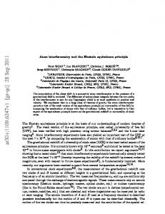
Fig. 4. Simplified scheme of the apparatus used to observe Bloch oscillations and to measure g: Sr atoms are laser cooled and trapped at a temperature of about 400 nK in a red magnetooptical-trap (MOT). The MOT laser beams are then switched-off and the atoms are transferred in a vertical 1-dimensional optical lattice generated by a laser beam retroreflected by a mirror; atoms are confined in series of layers at the maxima of the standing wave by the dipole force. We measure the momentum distribution of the atoms, after the coherent evolution in the potential given by the periodic potential plus gravity, by a time-of-flight measurement, after a free fall of 12 ms, using a resonant probe laser beam and absorption imaging on a CCD camera.
tential gives rise to Bloch oscillations at frequency νB given by νB =
mgλL 2h
(3)
where m is the atomic mass, g is the acceleration of gravity, λL is the wavelength of the light producing the lattice, and h is Plancks constant. Since both λL and m are well known, the overall force along the lattice axis can be determined by measuring the Bloch frequency νB . In order to do a force measurement with given interrogation time, the atomic wavefunction has to undergo a coherent evolution on the same time timescale. The most common effects limiting the coherence time for ultracold atoms are perturbations due to electromagnetic fields and atom-atom interactions. 88 Sr is in this respect a good choice because in the ground state it has zero orbital, spin and nuclear angular momentum that makes it insensitive to stray electric and magnetic fields that otherwise need to be shielded. In addition, 88 Sr has remarkably small atom-atom interactions;33 this prevented so far the achievement of Bose-Einstein condensation for this atom33,34 but becomes an important feature in experiments where collisions lead to a loss of coherence limiting the measurement time and the potential sensitivity. Given the small extension of ultracold Sr atoms confined in optical lattice potential, and its insensitivity to stray fields and elastic collisions, Sr in optical lattices results to be a unique sensor for small-scale forces with better performances and reduced complexity compared to proposed schemes using degenerate Bose35 or Fermi36 gases. This improves the feasibility of new experiments on gravity in unexplored regions.
February 16, 2007
23:9
WSPC - Proceedings Trim Size: 9.75in x 6.5in
main
8
3.1. Experimental apparatus The experimental setup used in this work is schematically shown in Fig. 4. The method used to produce ultracold Sr atoms was already described in Ref. 37. The experiment starts with trapping and cooling ∼ 5 × 10⁷ 88 Sr atoms at 3 mK in a magneto-optical trap (MOT) operating on the 1 S0 -1 P1 blue resonance line at 461 nm. The temperature is then further reduced by a second cooling stage in a red MOT operating on the 1 S0 -3 P1 narrow transition at 689 nm and finally we obtain ∼ 5 × 10⁵ atoms at 400 nK. After this preparation phase, that takes about 500 ms, the red MOT is switched off and a one-dimensional optical lattice is switched on adiabatically in 50 µs. The lattice potential is originated by a single-mode frequencydoubled Nd:YVO4 laser (λL = 532 nm) delivering up to 350 mW on the atoms with a beam waist of 200 µm. The beam is vertically aligned and retro-reflected by a mirror producing a standing wave with a period λL /2 = 266 nm. The corresponding photon recoil energy is ER = h2 /2mλ2L = kB × 381 nK. As expected from band theory,38 the amplitude of the oscillation in momentum space decreases as the lattice depth is increased. This suggests that in order to measure the Bloch frequency with maximum contrast the intensity of the lattice laser should be reduced. On the other hand, reducing the intensity results in a loss in the number of trapped atoms because of the smaller radial confinement. For this reason, we used a lattice depth of 10 ER . For a lattice potential depth corresponding to 10 ER , the trap frequencies are 50 kHz and 30 Hz in the longitudinal and and radial direction, respectively. Before being transferred in the optical lattice, the atom cloud in the red MOT has a disk shape with a vertical size of 12 µm rms. In the transfer, the vertical extension is preserved and we populate about 100 lattice sites with 2×10⁵ atoms with an average spatial density of ∼ 1011 cm−3 . After letting the atoms evolve in the optical lattice, the lattice is switched off adiabatically and we measure the momentum distribution of the sample by a time-of-flight measurement, after a free fall of 12 ms, using a resonant probe laser beam and absorption imaging on a CCD camera. Fig. 5 shows time-of-flight images of the atoms recorded for different times of evolution in the optical lattice potential after switching-off the MOT. In the upper part of the frames, the atoms confined in the optical lattice can be seen performing Bloch oscillations due to the combined effect of the periodic and gravitational potential. The average force arising from the photon recoils transferred to the atoms compensates gravity. 3.2. Data analysis The images obtained by absorption imaging, as the ones shown in Fig. 5, are integrated along the horizontal direction and fitted with the sum of two Gaussian functions. From each image, two quantities are extracted : the first is the vertical momentum distribution of the lower peak . The second is the width of the atomic momentum distribution (i.e. the second momentum of the distribution) . We find that the latter is less sensitive against noise-induced perturbations to the vertical momentum. We observed ∼ 4000 Bloch oscillations in a time t = 7 s. During this
February 16, 2007
23:9
WSPC - Proceedings Trim Size: 9.75in x 6.5in
main
9
Fig. 5. Time-of-flight images of the atoms recorded for different times of evolution in the optical lattice potential after switching-off the MOT. In the upper part of each frame, the atoms confined in the optical lattice perform Bloch oscillations for the combined effect of the periodic and gravitational potential. The average force arising from the photon recoils transferred to the atoms compensates gravity. In the lower part, untrapped atoms fall down freely under the effect of gravity.
time, about 8000 photon momenta are coherently transferred to the atoms. Oscillations continue for several seconds and the measured damping time of the amplitude is τ ∼ 12 s. To our knowledge, the present results for number of Bloch oscillations, duration, and the corresponding number of coherently transferred photon momenta, are by far the highest ever achieved experimentally in any physical system. From the measured Bloch frequency νB = 574.568(3) Hz we determine the gravity acceleration along the optical lattice g = 9.80012(5) ms−2 . The overall estimated sensitivity is 5×10⁻⁶ g and, neglecting the 500 ms preparation of the atomic sample, we have a sensitivity of 4 × 10⁻⁵ g at 1 second. We expect that a sensitivity of 10−7 g can be achieved using a larger number of atoms, and reducing the initial temperature of the sample. Apart from collisional relaxation, which should contribute to decoherence on a minute timescale, the main perturbation to quantum evolution is represented by vibrations of the retro-reflecting mirror.39 Minor contributions to decoherence may come from the axial momentum dispersion of the lattice at 10−6 due to its radial extension. 3.3. Testing the Newtonian gravity law The micrometric spatial extension of the atomic cloud in the vertical direction, and the possibility to load it into the optical potential at micrometric distance from a surface, makes the scheme we demonstrated particularly suitable for the investigation of forces at small spatial scales. The possibility of investigating the gravitational force at small distances by atomic sensors was proposed in Ref. 11, discussed in detail in Ref. 40, and preliminarly demonstrated in Ref. 41. Deviations from the Newtonian law are usually described assuming a Yukawa-type potential V (r) = −G
m1 m2 (1 + αe−r/λ ) r
(4)
where G is Newton gravitational constant, m1 and m2 are the masses, r is the distance between them. The parameter α gives the relative strength of departures from Newtonian gravity and λ is its spatial range. Experiments searching for possible deviations have set bounds for the parameters α and λ. Recent results using
February 16, 2007
23:9
WSPC - Proceedings Trim Size: 9.75in x 6.5in
main
10
microcantilever detectors lead to extrapolated limits α ∼ 104 for λ ∼ 10 µm and for distances ∼ 1 µm it was not possible to perform direct experiments so far.19,20 The small size and high sensitivity of the atomic probe allows a direct, modelindependent measurement at distances of a few µm from the source mass with no need for modeling and extrapolation as in the case of macroscopic probes. This allows to directly access unexplored regions in the α − λ plane. Also, in this case quantum objects are used to investigate gravitational interaction. Our results indicate that our Sr atoms when brought close to a thin layer can be used as probe for the gravitational field generated by the massive layer.42 If we consider, in fact, a material of density ρ and thickness d, the added acceleration of gravity in proximity of the source mass is a = 2πGρd so that when d ∼ 10 µm and ρ ≃ 10 g/cm3 ) as for tungsten crystals the resulting acceleration is a ∼ 4 × 10⁻¹¹ ms−2 . Measuring νB at a distance ∼ 4 µm away from the surface would allow to improve the constraint on α by two orders of magnitude at the corresponding range λ ∼ 4 µm. Spurious non-gravitational effects (Van der Waals, Casimir forces), also present in other experiments, can be reduced by using an electrically conductive screen and performing differential measurements with different source masses placed behind it. Moreover, by repeating the same experiment with the 4 stable isotopes (3 bosons, 1 fermion, with atomic mass ranging from 84 to 88), we can further discern among gravitational and other forces. Acknowledgements This work was supported by Istituto Nazionale di Fisica Nucleare, LENS, Ente Cassa di Risparmio di Firenze. References 1. A. Peters, K. Y. Chung and S. Chu, Metrologia 38, p. 25 (2001). 2. M. J. Snadden, J. M. McGuirk, P. Bouyer, K. G. Haritos and M. A. Kasevich, Phys. Rev. Lett. 81, p. 971 (1998). 3. J. M. McGuirk, G. T. Foster, J. B. Fixler, M. J. Snadden and M. A. Kasevich, Phys. Rev. A 65, p. 033608 (2002). 4. T. L. Gustavson, P. Bouyer and M. Kasevich, Phys. Rev. Lett. 78, p. 2046 (1997). 5. T. L. Gustavson, A. Landragin and M. A. Kasevich, Class. Quantum Grav. 17, p. 2385 (2000). 6. D. S. Weiss, B. C. Young and S. Chu, Phys. Rev. Lett. 70, p. 2706 (1993). 7. R. Battesti, P. Clad´e, S. Guellati-Kh´elifa, C. Schwob, B. Gr´emaud, F. Nez, L. Julien and F. Biraben, Phys. Rev. Lett. 92, p. 253001 (2004). 8. P. R. Berman (ed.), Atom interferometry (Academic press, Chestnut Hill, 1997). 9. S. Fray, C. A. Diez, T. W. Haensch and M. Weitz, Phys. Rev. Lett. 93, p. 240404 (2004). 10. S. Dimopoulos, P. Graham, J. Hogan and M. Kasevich, arXiv:gr-qc/0610047 (2006). 11. G.M. Tino, in 2001: A Relativistic Spacetime Odyssey - Proceedings of JH Workshop, Firenze, 2001 (I. Ciufolini, D. Dominici, L. Lusanna eds., World Scientific, 2003). Also, Tino G. M., Nucl. Phys. B 113, 289 (2003).
February 16, 2007
23:9
WSPC - Proceedings Trim Size: 9.75in x 6.5in
main
11
12. G. Ferrari, N. Poli, F. Sorrentino and G. M. Tino, Phys. Rev. Lett. 97, p. 060402 (2006). 13. C.Bord´e, G.M.Tino and F.Vetrano, 2004 Aspen Winter College on Gravitational Waves. http://www.ligo.caltech.edu/LIGO web/Aspen2004/pdf/vetrano.pdf. 14. Chiao, Y. Raymond, Speliotopoulos and D. Achilles, Journal of Modern Optics 51(67), p. 861 (2004). 15. A. Roura, D. Brill, B. Hu, C. Misner and W. Phillips, Phys. Rev. D 73, p. 084018 (2006). 16. P. Delva, M.-C. Angonin and P. Tourrenc, Phys. Lett. A 357, p. 249 (2006). 17. N. Sneeuw, R. Rummel and J. M¨ uller, Class. Quantum Grav. 13, p. A113 (1996). 18. M. Antezza, L. P. Pitaevskii and S. Stringari, Phys. Rev. Lett. 95, p. 113202 (2005). 19. J. C. Long, H. W. Chan, A. B. Churnside, E. A. Gulbis, M. C. M. Varney and J. C. Price, Nature 421, p. 922 (2005). 20. S. J. Smullin, A. A. Geraci, D. M. Weld, J. Chiaverini, S. Holmes and A. Kapitulnik, Phys. Rev D 72, p. 122001 (2005). 21. P. J. Mohr and B. N. Taylor, Rev. Mod. Phys. 77-1, 42 (2005). 22. J. Stuhler, M. Fattori, T. Petelski and G. M. Tino, J. Opt. B: Quantum Semiclass. Opt. 5, p. S75 (2003). 23. A. Bertoldi, G. Lamporesi, L. Cacciapuoti, M. D. Angelis, M. Fattori, T. Petelski, A. Peters, M. Prevedelli, J. Stuhler and G. M. Tino, Eur. Phys. J. D 40, p. 271 (2006). 24. J. B. Fixler, G. T. Foster, J. M. McGuirk and M. Kasevich, Science 315, p. 74 (2007). 25. R. Legere and K. Gibble, Phys. Rev. Lett. 81, p. 5780 (1998). 26. L. Cacciapuoti, M. de Angelis, M. Fattori, G. Lamporesi, T. Petelski, M. Prevedelli, J. Stuhler and G. M. Tino, Rev. Sci. Instrum. 76, p. 053111 (2005). 27. J. Schurr, F. Nolting and W. K¨ undig, Phys. Rev. Lett. 80, p. 1142 (1998). 28. M. Fattori, G. Lamporesi, T. Petelski, J. Stuhler and G. Tino, Phys. Lett. A 318, p. 184 (2003). 29. I. Bloch, Nat. Phys. 1, p. 253001 (2005, and references therein). 30. F. Bloch, Z. Phys. 52, p. 555 (1929). 31. M. Raizen, C. Salomon and Q. Niu, Physics Today 50 (1997, and references therein). 32. M. Takamoto, F.-L. Hong, R. Higashi and H. Katori, Nature 435, p. 321 (2005). 33. G. Ferrari, R. E. Drullinger, N. Poli, F. Sorrentino and G. Tino, Phys. Rev. A 73, p. 23408 (2006). 34. T. Ido, Y. Isoya and H. Katori, Phys. Rev. A 61, p. 061403(R) (2000). 35. B. P. Anderson and M. A. Kasevich, Science 282, p. 1686 (1998). 36. G. Roati, E. de Mirandes, F. Ferlaino, H. Ott, G. Modugno and M. Inguscio, Phys. Rev. Lett. 92, p. 230402 (2004). 37. N. Poli, R. E. Drullinger, G. Ferrari, J. L´eonard, F. Sorrentino and G. M. Tino, Phys. Rev. A 71, p. 061403(R) (2005). 38. N. Ashcroft and N. Mermin, Solid State Physics (Saunders, 1976). 39. Independent measurements with an accelerometer at the level of the retro-reflecting mirror indicate a seismic noise consistent with the observed damping time. 40. S. Dimopoulos and A. A. Geraci, Phys. Rev. D 68, p. 124021 (2003). 41. D. M. Harber, J. M. Obrecht, J. M. McGuirk and E. A. Cornell, Phys. Rev. A 72, p. 033610 (2005). 42. S. Kuhr, W. Alt, D. Schrader, M. Mueller, V. Gomer and D. Meschede, Science 293, p. 278 (2001).