flexibility toward meeting design targets, such as area, power, and delay. ... The sin- gle stuck-at-fault model assumes that the physical defects manifest .... wire, in practice, not only wires but also gates are added or .... Design Automation and Test in Europe, 1998, pp. .... IEEE/ACM International VLSI Design 2000, pp. 268- ...
ATPG-based Logic Synthesis: An Overview Chih-Wei Jim Chang
Malgorzata Marek-Sadowska
Cadence Design Systems, Inc. San Jose, CA 95134
Department of Electrical and Computer Engineering, University of California, Santa Barbara, CA 93106, USA
Abstract The ultimate goal of logic synthesis is to explore implementation flexibility toward meeting design targets, such as area, power, and delay. Traditionally, such flexibility is expressed using “don’t cares” and we seek the best implementation that does not violate them. However, the calculation and storing of don’t care information is CPU and memory-intensive. In this paper, we give an overview of logic synthesis approaches based on techniques developed for Automatic Test Pattern Generation (ATPG). Instead of calculating and storing don’t cares explicitly, ATPG-based logic synthesis techniques calculate the flexibility implicitly. Low CPU and memory usage make those techniques applicable for practical industrial circuits. Also, the basic ATPG-based logic level operations create predictable, small layout perturbations, making an ideal foundation for efficient physical synthesis. Theoretical results show that an efficient, yet simple add-a-wire-and-remove-a-wire operation covers all possible complex logic transformations.
soning techniques such as ATPG and SAT usually explore the implicitly represented freedom. In this overview, we focus on the ATPG-based techniques to explore flexibility in gate-level Boolean networks. Specifically, we focus on the concept of Redundancy-Addition-and-Removal (RAR). The idea is to add one redundant wire to a circuit to make a previously-irredundant wire redundant, and hence removable. This simple operation, as will be explained later, forms the basis for all possible complex logic transformations. This paper is structured as follows: in Section 2, we briefly introduce some fundamental concept of ATPG. In Section 3, we contrast ATPG applied to manufacturing testing from applied for logic synthesis. The basic concept of redundancy-addition-and-removal is also introduced there. In Section 4, we study the recent advancements in RAR as well as its theoretical completeness in solving the logic synthesis problems. A long list of applications is reviewed in Section 5 followed by the conclusions in Section 6.
1. Introduction
2. Preliminaries
Logic synthesis is an essential step in today’s integrated circuit design. It translates the designer’s intention, often written in register-transfer-level (RTL), to a gate-level netlist which satisfies a given specification. The gate-level netlist is an interconnection of a set of logic gates, state elements, and macro blocks such as randomaccess memory or acquired intellectual property. The combinational part of the netlist is often modeled as a Boolean network[1], in which each node implements a Boolean function. The logic synthesis tools try to find a Boolean network that satisfies specific constraints, such as area, power, and timing. The gate-level netlist is then fed to placement and routing tools for final physical implementation. Logic synthesis techniques allow for changing a given netlist and maintaining its logic equivalence to the original specification. The term “flexibility” is loosely defined as representing the existence of such restructuring opportunity in the presence of the constraint of logic equivalence. Most of the existing logic synthesis techniques are in a sense exploring such flexibility to achieve specific goals. To explore the flexibility of Boolean networks, some basic tools are needed to determine what is allowed and what is not. In general, three major techniques exist for this purpose: test generation, binary decision diagrams[2], and satisfiability (SAT)[14]. Techniques used to represent flexibility fall into two main categories: explicit representation and implicit representation. The explicit representation calculates and records the implementation’s freedom in certain forms, such as matching patterns[1], don’t cares[1], or SPFD[28]. Usually, BDDs are involved in recording such information. These representations often demand large storage and intensive computation. Implicit techniques do not require that the freedom is recorded a priori. Instead, the freedom is explored whenever it is needed. Rea-
Here we briefly review pertinent terminology used in test generation. After a chip has been designed and fabricated, it is necessary to test it to determine whether it is working correctly. This is done by applying input vectors and then capturing and analyzing the output response. For a sequential circuit with n primary inputs and p flipflops, exhaustive testing would require applying 2n+p vectors. For even moderate size circuits, this may take too much time. The single stuck-at-fault model assumes that the physical defects manifest themselves as wires which are permanently connected to either Vdd or GND, and that only one such stuck-at wire exists in a given circuit. In the single stuck-at-fault model, a wire w from a node nx to a node ny, denoted w(nx→ny), could be stuck at either 1 or 0. Let f be a multiple-input multiple-output Boolean function implemented by a combinational circuit C. ffaulty and fgood are the functions implemented by the faulty and good circuits, respectively. We use the Dnotation[22] to represent the fault effect. D (1/0) means that in the good circuit, the value on a particular wire is 1 whereas in the faulty circuit the value on the same wire is 0. D denotes the opposite case. The fault on w is testable if there exists a primary input vector v such that fgood(v) ≠ ffaulty(v). That is, the difference between the good and faulty circuits can be observed at primary outputs when the primary input vector v is applied. When no vector exists which can distinguish the faulty from the good circuit, the fault on w is redundant and can be removed by assigning the constant stuck-atvalue on w. The process of finding such a vector v through algorithmic means is called Automatic Test Pattern Generation (ATPG). The processes of test generation and redundancy identification are known to be NP-hard.
1
a
f
b c
nx
d
wt s1 s2
e
Fig. 1: Recursive learning
s3
ny D1
s5 D2
s4
D3
s6
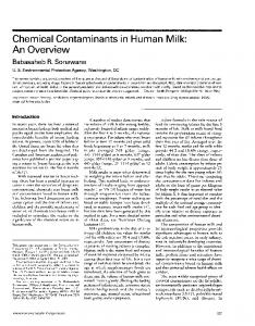
Fig. 2: Dominators and mandatory assignments that can detect the fault. Instead of finding all mandatory assignments, the concept of dominator can be used to find a subset of such assignments that are easy to compute. Such mandatory assignments are obtained by setting the side inputs of the dominators to their corresponding non-controlling values and setting the source of the faulty wire to its fault activating value. These two types of value assignments, along with their implications, form a subset of all possible mandatory assignments. The fault is redundant if its MAs are inconsistent, but when the MAs of a fault are consistent, redundancy is inconclusive.
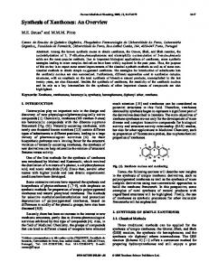
The input controlling value of a gate g is the logic value which, when set at any input of g, uniquely determines g’s output regardless of the logic values on other inputs. For example, when g is a NAND gate, the input controlling value of g is 0. XOR gate does not have an input controlling value because the output cannot be uniquely determined by any single input. Inverter and buffer have no input controlling value because they have only one input. The input non-controlling value of g is the opposite logic value of the corresponding input controlling value. Logic implication is a process of inferring consistent logic values based on known logic values. Given a logic value v assigned at the output of a gate g, the direction of implication can be forward or backward until no more logic values can be inferred. For simplicity, the input controlling value is generally referred to as the “controlling value” of a gate. Kunz and Pradhan proposed the notion of Recursive Learning [19] as a systematic way to identify indirect implications. For example, in Fig. 1, assume f is assigned 1. Since f is the output of an OR gate, no more direct implications are possible. Applying recursive learning on f, we can first set d to 1. Direct backward implication of d=1 leads to b=1. Next, we can set e to 1 and also imply b=1. The intersection of these two justifications gives b=1. That is, f=1 implies b=1. These dependencies can be determined using the AND-OR reasoning graph[20]. Since each justification can further spawn new justifications, a user-specified value, termed depth, is used to control the reasoning. The complexity of recursive learning is exponential with respect to the depth. The idea of a dominator was proposed by Kirkland and Mercer[18]. A dominator is a gate through which any fault effect has to pass to reach primary outputs. The dominators’ inputs which are not on the fault-propagation path have to be set to non-controlling values to allow the fault effect to propagate through. Fig. 2 illustrates the concept of a dominator. Here, wt is a target wire with a stuck-at-fault. Since all paths originating from wt have to pass nodes D1, D2, and D3, these nodes are the dominators of the wt stuck-at-fault. Side-inputs to the dominators s1, s2, s3, s4, s5 and s6 should be set to non-controlling values of the corresponding gates to allow fault-effect propagation. Also, ns must be set to the opposite value of v in order to activate the fault effect. For a fault to be testable, some nodes in the circuit must be set to a fixed value for any test vector. These value assignments are called the Mandatory Assignments. A formal definition is as follows:
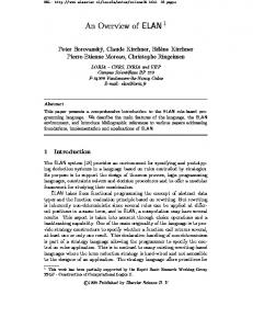
3. ATPG in Logic Synthesis - Redundancy Addition and Removal Historically, ATPG was developed to find manufacturing defects. For a given target fault, test pattern excites and propagates the fault effect to primary outputs. The goal is to find a set of test patterns which achieve the highest fault coverage. Circuit structures as well as testability calculation have been investigated to speed up the test generation process. Redundancy forms a link between ATPG and logic synthesis. It is possible that after exhausting the entire solution space, no test pattern is found for the target fault. In such a case, the fault is declared redundant and the test generator moves on to the next target fault. For a stuck-at-1 fault, being redundant means that permanently connecting this wire to 1 makes no difference as compared to the original circuit, because no test pattern can distinguish those two situations. Removing a redundant wire, in traditional logic synthesis context, can be viewed as reducing the number of literals by one. ATPG was used as an redundancy identification engine in [24]. When all the redundancies have been removed and the circuit is irredundant, we may ask: can the circuit be reduced further? In 1993, Cheng[13] and Entrena proposed a simple yet powerful concept: add a redundant wire to the circuit to make a previously-irredundant wire redundant. Take Fig. 3 for example. Consider the target wire g1→g4. To activate the stuck-at-1 fault on this wire, g1 is set to 0. Since g4, g8, and g9 are the dominators of this fault, the corresponding side inputs are set to non-controlling values. i.e. c=1, g7=0, and f=1. The value c=1 leads to g2=0. Now, g1=0 and g2=0 lead to g5=0. All together, the following MAs are implied: {g1=0, c=1, g2=0, g5=0, g7=0, f=1, g4=g8=g9=D}. As we mentioned previously, these logic values are mandatory for the target fault to be testable. At this point, no conflict exists. What if we artificially create a conflict? For example, we can add a new wire connecting g5 to g9. Since the MA on g5 is 0, it forces the output of g9 to be a 0. That is, the fault effect D is not observable after g9. This causes the target wire to be untestable and hence redundant. However, we cannot arbitrarily add a the wire from g5 to g9 without affecting the overall function-
Definition 1: Let ε be the stuck-at-v (v is either 0 or 1) fault on an irredundant target wire in a combinational Boolean network C, and let Γ be the set of all primary input vectors that can activate and propagate the fault effect to primary outputs. A node k in C has a mandatory assignment (MA) m if k is assigned the value m under all primary input vectors in Γ. Finding all mandatory assignments of a target fault is known to be an NP-hard problem, as it involves finding all the test vectors
2
underscores the significance of the simple wire-addition-andremoval operation.
c g4 b d
5. Applications
g1
One main advantage of ATPG-based restructuring technique is that it operates directly on the structural netlist description of the circuit so that the technical consequences of the performed transformations can be evaluated in an easy way, permitting better control of the optimization process with respect to the specific goals. In this section, we briefly discuss some key applications.
O1
g5 e c
g2 g6
d a b
g8 g7
g3
g9
O2
f
5.1 Literal Minimization
Fig. 3: Mandatory Assignment
Literal minimization is one of the most important goals at the technology-independent level of logic synthesis. Typically, fewer literals implies smaller area and potentially smaller power consumption. SIS[26] is one of the representative logic synthesis systems. The use of RAR for literal minimization were studied in [13][8][20] culminating in [10]. The idea is that if we could add one wire while removing two or more wires, the literal count decreases. It is shown in [10] that RAR-based technique achieves 14% better results than SIS script.rugged in terms of the number of literals while using only one sixth of the CPU time and a fraction of the memory compared to SIS.
ality. In [13], redundancy test based on MA is applied on each possible candidate wire to determine if it can be added. We note, that though the idea is to add a wire and then remove a wire, in practice, not only wires but also gates are added or removed. For example, in Fig. 3, adding the wire from g5 to g9 effectively changed the type of gate g9 from a two-input AND to a three-input AND. This wire can also be added to the output of g9 by adding a two-input AND. On the other hand, when the target wire g1→g4 is removed, g4 becomes a one-input AND which can be removed by connecting c to its output. Moreover, in this case, adding g5→g9 not only removes g1→g4 but also g6→g7. After removing g6→g7, g6 is hanging and can be removed. g7 becomes a single-input AND and can also be removed. The circuit shown in Fig. 3 could be a sub-circuit imbedded in a much larger netlist. The set of MAs calculated is not guaranteed to be complete since a complete set would necessitate a full justification back to the primary inputs of the larger circuit. This can be very time-consuming but not necessarily more fruitful, since MAs tend to be found closer to the target wire.
5.2 Timing Optimization The major advantage of the redundancy-addition-and-removal technique is that only wires are reconnected while logic gates are preserved. This property is especially desirable in the deep-submicron age, when timing estimation obtained during logic synthesis cannot be justified after placement and routing. Timing can be incrementally corrected through a sequence of rewiring steps guided by accurate physical information. Rewiring minimally perturbs layout and helps in achieving timing closure[3]. Post-layout timing optimization was studied in [17][15]. After global routing has been performed, when the interconnect effect can be accurately modeled, RAR is attempted on critical path wires. If adding a new wire and removing the target wire from the critical path leads to an overall shortened critical path, the move is taken. An algorithm combining buffer insertion and RAR was also proposed [17]. Another post-layout rewiring technique combining functional symmetry and gate sizing was proposed in [4]. In [25], timing optimization was performed by iterating restructuring and placement. Pre-layout timing optimization was studied in [12].
4. Deeper Understanding of RAR The number of required redundancy tests on candidate wires can be large. In [10], a set of rules are used as filters to screen out impossible candidates. Recently, we proposed a technique which does not require repetitive redundancy tests[5]. We briefly go through the fundamental concepts in [5]. Let wt be the target wire to be removed and wa to be a redundant wire that, when added, makes the target wire wt redundant. wa is an alternative wire of wt. On the other hand, wt can also be viewed as an alternative wire of wa. By exploring this mutual alternative property, [5] proved that for wa to be an alternative to wt, the MA of wa must result in a conflict on wt. We may start the uncontrollability and unobservability propagation defined in [16] on wt and directly capture wa as a result of the propagation. There is no need to perform repetitive redundancy testing on the set of candidate wires. Up to an order of magnitude of speedup has been observed as a result of this observation. One may ask: can we explore all possible network transformations just by adding a wire and removing another wire(s)? Affirmative answer was given by Kunz et. al. in [20]. They proved theoretically that given any two equivalent circuits C1 and C2, there exists a sequence of wire addition and removal operations which can bring the circuit from C1 to C2, or vice versa. This result
5.3 Power Optimization Power consumption and speed are two primary cost functions in today’s integrated circuit design. As mobile computation devices prevail in the market, the ability to design fast, low-power devices is of paramount importance. However, these two objectives are often conflicting: a faster circuit consumes more power, but a lowpower circuit runs slower. Hence, designers often need to trade off power for speed and vice versa to meet the desired specifications. Rewiring changes the structure of a netlist and hence affects the switching probability. Effective capacitance, measured by the product of switching probability and the load capacitance, is directly proportional to the power consumption. In [23] and [29], rewiring-based techniques for power optimization were studied.
3
5.4 Other Applications
Removal Technique”, in Proc. of EURO-DAC, 1996, pp. 342347. [13]L. A. Entrena and K. -T. Cheng, “Combinational and Sequential Logic Optimization by Redundancy Addition and Removal”, IEEE Trans. on Computer-Aided Design, pp. 909916, July 1995 [14]M. Davis and H. Putnam, “A Computing Procedure for Quantification Theory,” Journal of ACM, vol. 7, pp. 201-215, 1960. [15]R. C-Y. Huang, Y. Wang, and K.-T. Cheng, “Libra - A LibraryIndependent Framework for Post-Layout Performance Optimization,” in Proc. of Intl. Symposium on Physical Design, April 1998, pp. 135-140. [16]M. A. Iyer and M. Abramovici, “FIRE: A Fault-Independent Combinational Redundancy Identification Algorithm”, IEEE Trans. on VLSI, vol. 4, no. 2, pp. 295-301, June. 1996. [17]Y.-M. Jiang, A. Krstic, K. -T. Cheng, and M. Marek-Sadowska, “Post-Layout Logic Restructuring for Performance Optimization”, in Proc. of Design Automation Conf., 1997, pp. 662-665. [18]T. Kirkland and M. R. Mercer, “A Topological Search Algorithm for ATPG,” in Proc. Design Automation Conf., June 1987, pp. 502-508. [19]W. Kunz, and D. Pradhan, “Recursive Learning: A New Implication Technique for Efficient Solutions to CAD Problems: Test, Verification and Optimization”, IEEE Trans. on Computer-Aided Design, vol. 13, no. 9, pp 1143-1158, Sep. 1994. [20]W. Kunz, D. Stoffel, and P. R. Menon, “Logic Optimization and Equivalence Checking by Implication Analysis”, IEEE Trans. on Computer-Aided Design, vol. 16, no. 3, pp. 266-281, Mar. 1997. [21]C.-C. Lin, K.-C. Chen, S.-C. Chang, M. Marek-Sadowska, and K.-T. Cheng, “Logic Synthesis for Engineering Change,” in Proc. of Design Automation Conf., 1995, pp. 647-652. [22]J. P. Roth, “Diagnosis of automata failures: A calculus and a method,” IBM J. Res. Develop., vol 10, pp. 278-291, July 1966. [23]D. K. Pradhan, M. Chatterjee, M. V. Swarna, and W. Knuz, “Gate-Level Synthesis for Low-Power Using New Transformations,” in Proc. Intl. Symp. on Low Power Electronics Design, 1996, pp. 297-300. [24]M.H. Schulz and E. Auth, “Advanced Automatic Test Pattern Generation and Redundancy Identification Techniques”, Proc. 18th Intl. Symp. on Fault Tolerant Computing, pp.30-35, 1988. [25]C. Stenz, B. M. Riess, B. Rohfleisch, and F. M. Johannes, “Performance Optimization by Interacting Netlist Transformations and Placement”, IEEE Trans. on Computer-Aided Design, vol. 19, No. 3, pp. 350-358, 2000 [26]“SIS: A System for Sequential Circuit Synthesis”, Report M92/41, University of California, Berkeley, May, 1992 [27]Y.L. Wu, W.N. Long, and H.B. Fan, “A Fast Graph-Based Alternative Wiring Scheme for Boolean Networks,” Proc. IEEE/ACM International VLSI Design 2000, pp. 268-273 [28]S. Yamashita, H. Sawada, and A. Nagoya, “SPFD: A New Method to Express Functional Flexibility,” IEEE Trans. on Computer-Aided Design, vol. 19, no. 8, Aug. 2000. [29]Q. Wang, S.B.K. Vrudhula, G. Yeap, and S. Ganguly, “Power Reduction and Power-Delay Trade-Offs Using Logic Transformations,” ACM Trans. on Design Automation of Electronic Systems, vol. 4, no. 1, pp. 97-121, Jan. 1999.
RAR can also be used to find Boolean divisors efficiently and to perform substitution [9], to compute local don’t care sets [7], to improve testability [11], and to perform synthesis for engineering change [21]. The problem of simultaneous removal of multipleredundancies was studied in [6]. RAR based on pattern matching was discussed in [27].
6. Conclusion In this paper, we have briefly reviewed the fundamental concepts of ATPG in context of applications to logic synthesis. Bridging ATPG and logic synthesis, Redundancy-Addition-and-Removal techniques provide an efficient engine to explore the flexibility in Boolean networks. We have reviewed different approaches from both theoretical and application points-of-view. With low CPU and memory usage, adaptable to a wide array of applications, this technique is a fundamental building block in coping with today’s logical/physical design challenges.
References [1] R. Brayton, G. Hachtel, and A. Sangiovanni-Vincentelli, “Multilevel Logic Synthesis”, in Proc. IEEE, vol. 78, no. 2, pp. 264300, Feb. 1990. [2] R. Bryant, “Graph-based Algorithms for Boolean Function Manipulation,” IEEE Trans. on Computers, C-35(8), pp. 677691, Aug. 1986. [3] C. -W. Chang, “Rewiring Techniques for Deep-Submicron Design Closure”, Ph.D. Dissertation, Department of Electrical and Computer Engineering, University of California, Santa Barbara, 2001 [4] C. -W. Chang, C. -K. Cheng, P. Suaris, and M. Marek-Sadowska, “Fast Post-placement Rewiring Using Easily Detectable Functional Symmetries”, in Proc. of Design Automation Conference, pp. 286-289, 2000 [5] C.-W. Chang and M. Marek-Sadowska, “Single-Pass Redundancy Addition and Removal”, in Proc. of Intl. Conf. on Computer-Aided Design, pp. 606-609, 2001 [6] S.-C. Chang, D. I. Cheng, and C.-W. Yeh, “On Removing Multiple Redundancies in Combinational Circuits,” in Proc. of Design Automation and Test in Europe, 1998, pp. 738.742. [7] S.-C. Chang and M. Marek-Sadowska, “An Efficient Algorithm for Local Don’t Care Sets Calculation,” in Proc. of Design Automation Conf., 1995, pp. 663-667. [8] S.-C. Chang, M. Marek-Sadowska, and K.-T. Cheng, “Perturb and Simplify: Multi-level Boolean Network Optimizer,” IEEE Trans. on Computer-Aided Design, vol. 15, no. 12, pp. 14941504, Dec. 1996. [9] S.-C. Chang and D. I. Cheng, “Efficient Boolean Division and Substitution Using Redundancy Addition and Removing,” IEEE Trans. on Computer-Aided Design, vol. 18, no. 8, Aug. 1999. [10]S.-C. Chang, L.P.P.P. Van Ginneken, and M. Marek-Sadowska, “Circuit Optimization by Rewiring”, IEEE Transactions on Computers, vol. 48, no. 9, pp.962-970, Sep. 1999. [11]M. Chatterjee, D. K. Pradhan, and W. Knuz, “LOT: Logic Optimization with Testability − New Transformations for Logic Synthesis,” IEEE Trans. on Computer-Aided Design, vol. 17, no. 5, May 1998. [12]L. A. Entrena, J. A. Espejo, E. Olias, and J. Uceda, “Timing Optimization by an Improved Redundancy Addition and
4