Encoding Algorithms for Logic Synthesis Valery Sklyarov, Iouliia Skliarova University of Aveiro, Department of Electronics, Telecommunications and Informatics/IEETA 3810-193 Aveiro, Portugal
[email protected],
[email protected]
Abstract This paper presents an encoding algorithm that is very efficient for many different logic synthesis problems. The algorithm is based on the use of special tables and includes two basic steps: searching for predefined graphical shapes in the tables, and swapping coded variables in the tables taking into account some constraints. The latter are specified with the aid of an auxiliary graph that reflects the overlap between coded variables in different subsets that have to be accommodated in the tables. The examples in the paper and the results of experiments have shown that the use of the proposed algorithm for state encoding allows the number of logic elements for combinational circuits of finite state machines to be decreased.
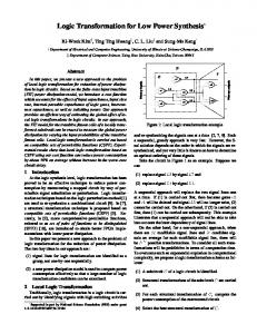
1. Introduction Encoding algorithms (such as [1-4]) are widely used for synthesis and optimization of digital circuits. We will consider such a technique that enables us to construct systems of Boolean functions, and then to decompose these systems into sub-systems for which we are able to reduce dependency of the functions, included into each sub-system, on respective arguments [5]. Using this technique permits many logic synthesis problems to be simplified [6,7]. For example, it enables us to decompose a finite state machine (FSM) into blocks, such as that shown in fig. 1, where variables τ1,...,τR and D1,...,DR provide interactions between the FSM memory and the combinational circuit. Let us first consider some of the advantages of this structure. The blocks Sax1,…,SaxT can be constructed in such a way that X1∩…∩XT = ∅ [7] and X = {x1,…,xL} = X1∪…∪XT, where x1,…,xL are input variables of the FSM. As a result, we can distribute input variables between different blocks. This allows many topological problems to be simplified. Besides, the structure in fig. 1 is very well suited for matrix implementation [6]. Note that the output variables from
the set Y = {y1,…,yN} = Y1∪…∪YT can be distributed in the same manner [7]. The considered approach to state encoding can be applied directly to the structure in fig. 1. Indeed we can determine such sub-functions that do not depend on the input variables from the set X and implement these subfunctions in an autonomous circuit, such as SaT+1. This circuit can be constructed using two possible methods. The first method incorporates the autonomous circuit into blocks Sax1,…,SaxT in such a way that we will be able to distribute outputs D1,…,DR between different groups of blocks Sax1,…,SaxT. The main advantage of this method is that the block SaT+1 becomes unnecessary. The second method assumes that all the variables D1,…,DR have been distributed between two sets, Dax and Da, in such a way that Dax∩Da=∅, and the active values of variables from Dax and Da will be obtained as outputs from blocks Sax1,…,SaxT and SaT+1 accordingly. The main idea is to extract the essential part of the logic from Sax1,…,SaxT and then to implement the extracted logic in SaT+1 as simply as possible. A similar approach can be followed in order to solve optimization problems in many practical applications, such as microinstruction encoding in microprogramming, matrix-based implementation of digital circuits, etc.
X1
S
S ax 1
XT
S ax T
τ 1 ,… ,τ R
S a T+1
FSM memory
D 1 ,… ,D R Y1
YT
Figure 1. Block decomposition of FSM
2. Example Let us consider an example from [8]. An FSM can be described as shown in Table 1 (at the beginning let us ignore all symbols enclosed in parentheses). Here, afrom is an initial state, ato - is the next state, K(afrom) and K(ato) - are the codes of the states afrom and ato, respectively, X(afrom,ato) - is a product of inputs that forces a corresponding state transition. We assume that FSM memory is built from D flip-flops. Let us consider various transitions from the same state. We can see that for all conditional transitions (i.e. for all transitions except from the state a6), all the sub-functions of D1,...,D3 that must be activated on transitions from a state, depend on both the state and inputs. We will say that a sub-function is active if it has to be assigned to 1. Since all the sub-functions depend on states and inputs, the relevant Boolean expressions, that are used to calculate the values D1,...,D3, contain variables from the full set {x1,...,xL,τ1,...,τR}, where L - is the number of external inputs (in our example L=5) and R - is the size of the FSM memory (in our example R=3). Consider all sub-functions of D1,...,D3 that are generated for proper transitions from a state. For example, sub-functions D13,...,D33, that have to be activated in transitions from the state a3 (later we will also mark such sub-functions with a corresponding superscript) are the following: D13 = a3x1; D23 = a3 (not_x1 ∨ not_x2); D33 = a3not_x1 (these expressions can easily be obtained from Table 1). Note that since there exist 3 transitions from a3, they can be distinguished with the aid
afrom a1
K(afrom) 000 (000)
a2
001 (011)
a3
010 (001)
a4
011 (100)
a5
100 (101)
a6 a7
101 (010) 110 (111)
of just two Boolean variables, such as D13,...,D33. As a result, inputs such as x1 and x2 can affect (and change) just two variables from the set {D13,...,D33} and the remaining variables (in our example one variable from the set { D13,...,D33}) can be independent of external inputs from the set X = {x1,...,xL}, i.e. they will only depend on the current state (in our example on the state a3). If the number of different (non coinciding) next states in state transitions from am is equal to qm, then (R-intlog2qm) variables from the subset D1m,...,DRm can be independent of the input variables from the set X. Let us suppose now that the states for our example have been coded as shown in parentheses in Table 1. The values of the sub-functions D1r,...,D3r (r=1,2,...,M, M - is the number of FSM states and for our example M=7) that do not depend on input variables, are marked with bold and italic bold fonts. Note that the bold font has been used for passive values, and italic bold font for active values of the sub-functions. Now the combinational circuit S of the FSM can be decomposed into two sub-circuits in such a way that the first sub-circuit Sax implements all active values of D11,...,D3M that are not bold. The functions of Sax depend on both FSM inputs and states. The second sub-circuit Sa implements all active values of D11,...,D3M that are bold. The functions of Sa depend only on the states and for our example they are: D1 = a3 ∨ a6; D2 = a6 ∨ a7; D3 = a2 ∨ a6 ∨ a7; Such functions are well suited for minimization and are usually very simple.
Table 1. An example of FSM X(afrom,ato) ato K(ato) a1 x1x2 000 (000) not_x1 not_x 2 a2 001 (011) not_x 1x2 a3 010 (001) x1 not_x 2 a6 101 (010) a3 x3 010 (001) not_x 3 a5 100 (101) not_x 1 a4 011 (100) x1x2 a5 100 (101) x1 not_x 2 a7 110 (111) a1 not_x 4 000 (000) x4 a4 011 (100) a1 x1 000 (000) not_x 1 a6 101 (010) 1 a7 111 a2 x5 001 (011) not_x 5 a7 110 (111)
D(afrom,ato) - (-) D3 (D2,D3) D2 (D3) D1,D3 (D2) D2 (D3) D1 (D1, D3) D2,D3 (D1) D1 (D1, D3) D1,D2 (D1, D2, D3) - (-) D2,D3 (D1) - (-) D1,D3 (D2) D1,D2,D3 D3 (D2, D3) D1,D2 (D1, D2, D3)
find the set Dafrom that has the maximum possible number of elements). If Drfrom∈Dafrom then Drfrom satisfies the requirement considered above, i.e. it depends only on afrom. The encoding technique assumes special graphical shapes for different sets, such as K(afrom,ato), that have to be accommodated in the encoding table. These graphical shapes are the same as for Karnaugh maps. The required solution will be found after proper accommodation of appropriate shapes in the encoding table. Note that any set A(afrom) has to be accommodated in any cell within the relevant shape, such as rectangle. If the shape has more cells than required, the remaining cells might be occupied by other states, which do not have any relationship with the considered set A(afrom). Fig. 2 demonstrates this technique for the following FSM: A(a1) = {a1,a2,a5,a6}; A(a2) = {a1,a3,a20}; A(a3) = {a8,a10}; A(a4) = {a18,a19}; A(a5) = {a2,a6,a7}; A(a6) = {a5,a11}; A(a7) = {a2,a3}; A(a8) = {a9,a10,a11}; A(a9) = {a15,a17}; A(a10) = {a12,a13,a14}; A(a11) = {a3,a12}; A(a12) = {a7,a14}; A(a20) = {a4,a15,a16,a17}. Here all sub-sets A(afrom) containing just one element (i.e. representing unconditional state transitions) were skipped. It is obvious that all components of K(afrom,ato) for such subsets do not depend on the input variables. The encoding algorithm involves the following two major steps that are repeated sequentially:
3. Primary encoding algorithm The objective of the algorithm we will look at now is to reduce the functional dependency of outputs on inputs. This is a typical combinatorial algorithm [9]. It is based on the use of special tables that look like Karnaugh maps, but are actually different. Let us designate A(afrom) the set of states that can be reached through direct transitions from the state afrom. Let us assume that for any set A(afrom) the following requirement has been satisfied:
∨
ato∈A ( a from )
X (a from , ato ) ≡ 1
where X(afrom,ato) is a product of x1,…,xL that forces a corresponding transition. Suppose K(afrom,ato) is a set of codes, for the states ato and ato∈A(afrom). Since the expression above is valid, if for given afrom bit k in all codes K(afrom,ato) has values either 0 and don’t care (-), or 1 and don’t care, then the sub-function Dkfrom does not depend on input variables from the set X. Here Dkfrom is the sub-function of the function Dk that forms the proper value of the function Dk in any transition to the states ato∈A(afrom). This leads us to the following method of encoding. For each set K(afrom,ato), afrom=1,…,M, it is necessary to find partitioning π D ={Dafrom,Daxfrom}, for which Dafrom∪Daxfrom={D1from,...,DRfrom}, from from Da ∩Dax =∅, and D1from,...,DRfrom - correspond to bits 1,...,R of codes of K(afrom,ato), |Dafrom|⇒max (we want to from
τ2τ3 τ1=1
00
a4
01
a16
11 a15 10 a17 τ4τ5 00
τ2τ3
τ1=0
00
a1
a2
a6
a5
01
a20
a3
a7
a11
11
a13
a12
a14
a9
10
a18
a19
a8
a10
01
11
10
τ4τ5 00
01
11
10
Figure 2. Mapping and swapping processes for encoding tables
• Search for the appropriate place in the encoding table for one of the acceptable graphical shapes. Note that some states can appear in the table more than once. However, we must minimize the number of different codes for the same state, For instance, the two codes 00000 and 00001 (i.e. 0000-) for the state am are better than two codes such as 00010 and 00001. In the last case we must repeat all the required transitions from the state am twice (the first time for the code 00010 and the second time for the code 00001); • Swap states within any shape if required, i.e. when we are not able to accommodate a new subset A(afrom). There are some constraints on the swapping process and they will be examined below. Consider the graph Gξ, which reflects the following relationships: (amξas) ⇔ A(am) ∩ A(as) ≠ ∅. Vertices of Gξ correspond to symbols from the set A={a1,…,aM}. Two vertices am and as are connected with an edge if and only if the relationship (amξas) is satisfied. Each vertex am has been appended to the set A(am) and all vertices for which |A(am)|