Selectable by front key switches or DI input (binary code). Higher and lower ... In
case of 1 output: Expert PID control with auto tuning function .... Output method:.
Shimaden, Temperature and Humidity Control Specialists
°C %RH
MICROPROCESSOR-BASED
Series
SR253
AUTO-TUNING PID CONTROLLERS
&
®
NRTL /C
approved
BASIC FEATURES
1 / 1000 °C display and adjustment are possible. *Only for R.T.D. input (scale: 0.000~50.000 °C) Temperature can be set on the basic screen. The operability has been remarkably improved with the dialogue system introduced by the 4-digit LCD display on the front panel. The front display section and operation section have been designed dust-proof and drip-proof. *Equivalent to IEC529 Standards IP65 High Accuracy ± 0.1% High Sampling Cycle 0.2 sec. Auto-Tuning PID/Auto-Tuning PID+PID RA/DA Selectable User-Selectable Inputs (Thermocouple) User-Selectable Ranges Programmable-Scaling (DCmV, DCmA) Multi-Setting of 10 Set Values User Friendly Operation (Menu Driven) Universal Power Supply (100~240V AC ± 10%) Interface RS-422A/RS-232C/RS-485 96 (H) x 96 (W) x 140 (D) mm (Panel Depth: 125mm)
AN OUTLINE
Series
SR253
• High accuracy of 0.1% and multifunctional performance meet various types of process control needs. • SR253 Controller features multifunctional performance. Yet, with the use of the dialogue system by the 4-digit LCD display, operability has been improved to a high degree. • A variety of functions are built in, including types of event outputs, remote setting function, and external control input. With this unit connected with the sequencer on the production line, the production line will be automated. • With expert PID control system incorporated, a much more enhanced control operation is the result. As two-output control has become available, temperature control on the order of room temperature and control of a process involving heat generation are also available as both heating and cooling volumes are adjusted simultaneously.
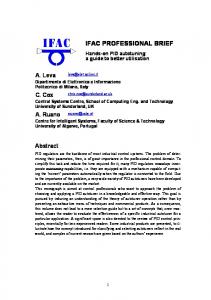
NAME & FUNCTION
Monitor Lamp Displays STBY : It flashes with "EXECUTE" set in standby mode. RUN : It flashes during ramp control and remains lit for temporary stop. ESV : It remains lit when SV No. is selected by external contact. REM : It remains lit when remote SV is selected. COM : It remains lit when the communication function is activated. EV1 : It remains lit when EV1 is activated. EV2 : It remains lit when EV2 is activated. EV3 : It remains lit when EV3 is activated. DO1 : It remains lit when DO1 is activated. DO2 : It remains lit when DO2 is activated. DO3 : It remains lit when DO3 is activated. DO4 : It remains lit when DO4 is activated. DO5 : It remains lit when DO5 is activated.
It illuminates and goes out when current or voltage is output. It illuminates with the contact or SSR drive voltage output ON.
Legend Display ˚C / ˚F Selectable
Sampling cycle : 0.2sec. Thermocouple : Multi-input and multirange (19 types) R.T.D. : Multi-range (16 types) Voltage : Multi-input and programmable scaling (14 types) Current : Multi-input and programmable scaling (2 types)
Action mode (output value) in operation and parameter set values are displayed on the 21-character and 4-line display (back-lighted).
PID Setting group
DISP
For returning to PV and SV screens and for moving to the initial screen of a group
GRP
For moving from one group to another group
SCRN
For moving from screen to screen in a group
Event / Do Setting group
For selecting on from two or more parameters For shifting For setting numerical values and parameters ENT
For registering set numerical values and items
Unit / Measuring Setting group
SPECIFICATIONS
Series
SR253
Display • LED display: • LCD display:
• LED lamp indication:
• Display accuracy:
• Temperature range for maintaining accuracy: • Display resolution: • Sampling cycle:
7-segment green LED 5 digits / height of character 14 mm Measured value (PV) display 128 x 32 full dot matrix liquid crystal display (Basic display 21 digits, 4 lines with LED back light) Set value (SV), SV No. display and set parameter display Action (status) display 16 types for 1 output, 17 types for 2 outputs AT, MAN, STBY, RUN, ESV, REM, COM, EV1, EV2, EV3, DO1, DO2, DO3, DO4, DO5, OUT1, OUT2 TC input: ±(0.1% FS+1˚C) Pt input: ±(0.1% FS+0.1˚C) mV, mA input: ±(0.1% FS+1digit) 23˚C±5˚C Depends on measuring range and scaling (0.0001, 0.001, 0.01, 0.1, 1) 200 msec. (0.2 sec.)
Setting • Local setting: Setting range: Multi SV value setting: Multi SV value setting: Higher and lower limit setting limiter: • Remote setting: Setting accuracy: Setting signal: Sampling cycle: Remote scaling: Remote bias: Remote filter: • Local / remote switching: • Direct tracking function: • Ramp control: Setting range:
By 8 front key switches Same as measuring range Setting of 10 points maximum possible Selectable by front key switches or DI input (binary code) Higher / lower limit individual setting as desired within measuring range (lower limit value < higher limit value) By external analog signals Not insulated / standard (0~10V); Insulated / optional ±(0.1% FS+1digit) 0~10V, 1~5V DC, 4~20mA DC / Selectable from code selection table 3 times / sec. (200 / 400 msec.) Possible within measuring range (inverse scaling possible) ±9999 unit OFF, 1~300 Sampling cycle (Approx. 1 / 3 sec.) By front Key switch or external operation Remote set value switchable to local set value bumplessly Increment / Decrement control 1~9999 unit / min. or sec. individual setting (0.1~999.9 unit / min. or sec. individual setting)
Input • Thermocouple: External resistance allowable range: Input impedance: Burnout function: Cold junction temperature compensation: Internal cold junction temperature compensation accuracy: • R.T.D.: Lead wire tolerable resistance: Amperage:
B, R, S, K, E, J, T, N, PLII, PR40-20, WRe5-26, {L, U (DIN) 43710} Gold & iron-Chromel (multi input, multi range) 100Ω max. Influence of external resistance: 1µ V / 10Ω 500kΩ min. Standard feature (up scale) Selectable between internal cold junction temperature compensation / external cold junction temperature compensation
±1.0˚C (within range from 18 to 28˚C) JIS Pt / JPt 3-wire type (multi range) 5Ω max. / wire Approx. 1mA
SPECIFICATIONS • Voltage:
• • • •
Input impedance: Current: Receiving impedance: PV bias: PV filter: Isolation:
Series
SR253
-10~10, 0~10, 0~20, 0~50, 10~50, 0~100, -100~100mV DC or -1~1, 0~1, 0~2, 0~5, 1~5, 0~10, -10~10V DC (Multi input, programmable scaling) 500kΩ min. 4~20, 0~20mA DC (Multi input, programmable scaling) 250Ω ±9999 unit OFF, 1~300 sampling cycle (0.2 sec.) Insulated between input and DI input, outputs insulated from each other (Not insulated between input and system, remote input and CT input)
Control • Control mode:
• Control output 1 Multi PID: Control output 1 proportional cycle: • Control output 2 (applicable only to apparatus with optional function of 2 outputs) Multi PID: Control output 2 proportional cycle: • Control output type / rating:
Output resolution: Output accuracy: • Operation / output updating cycle: • Multi PID:
• • •
•
Zone PID mode: Control output 1 Proportional band: Integral time: Derivative time: Action hysteresis: Control output 2 Proportional band: Integral time: Derivative time: Action hysteresis: Dead band: Higher / lower output limiter: Setting range: Control output characteristics: External control input: Remote mode: Remote proportional coefficient: Remote primary delay time: Manual control Output setting range: Output resolution: Auto / manual switch:
• Isolation:
In case of 1 output: Expert PID control with auto tuning function In case of 2 output: Expert PID + PID control with auto tuning function During RA-Heating / cooling action During DA-Heat + heat action By PID No. 01~10 (10 types) 1~200 sec. (in case of contact or SSR drive voltage output)
By PID No. 01~10 (10 types) 1~200 sec. (in case of contact or SSR drive voltage output) Contact output: 240V AC / 2.5A (resistive load) Current output: 4~20mA DC / load resistance: 600Ω max. SSR drive voltage: 12±1.5V DC / load current: 30mA max. Voltage output: 0~10V DC / load current: 2mA max. Approx. 1/8000 (with current / voltage output) ±0.5% FS (5~100% output / within accuracy maintaining temperature range) 200 msec. Individual PID (10 types) setting for each SV no. and Remote SV. Zone PID, ie., PID setting for each zone of SV values is also possible. Selectable between individual PID and zone PID Off, 0.1~999.9% (OFF setting: On-Off action) Off, 1~6000 sec. (OFF setting: With manual reset) Off, 1~3600 sec. 1~9999 unit (during On-Off action) Off, 0.1~999.9% (OFF setting: On-Off action) Off, 1~6000 sec. Off, 1~3600 sec. 1~9999 unit (during On-Off action) -20000~20000 unit Higher limit / lower limit (to be set on every individual PID) -5.0~105.0% (lower limit > higher limit) RA / DA switchable by front key switch or external control input (DI) Remote input usable as external control input Remote SV input / external control input selectable Off, 0.1~999.9% Off, 1~9999 sec. Y, P: 0.0~100.0%, I, V: -5.0~105.0% 0.1% Balanceless bumpless action (within proportional band range) Switching by front key switch or external control input (DI) Insulated between control output and various inputs / outputs and system (not insulated between 1 output and 2 outputs)
SPECIFICATIONS
Series
SR253
Event Output (Option) • The number of outputs: • Output rating: • Setting / selection:
Total 3 points, from EV1 to EV3 Contact output 240V AC / 1.0A (resistive load) Individual setting (individual output) / Selectable from following 19 types (output designation)
1) DEV : Higher limit (deviation 2) DEV : Lower limit (deviation 3) DEV : Out of range (deviation 4) DEV : Within range (deviation 5) PV : Higher limit (absolute 6) PV : Lower limit (absolute 7) SV : Higher limit (absolute 8) SV : Lower limit (absolute 9) AT : Auto turning in execution 10) MAN : In manual operation
• Isolation:
value value value value value value value value
action) action) action) action) action) action) action) action) ON ON
11) REM : 12) RUN : 13) STBY : 14) SO : 15) PV SO : 16) REM SO : 17) DIR : 18) HBA :
In remote operation Ramp control in execution Control action not in execution Scale-over of PV and REM Scale-over of PV Scale-over of REM During direct output During heater break alarm output (option) : During heater loop alarm output (option)
ON ON ON ON ON ON ON ON
19) HLA
ON
DEV, PV and SV events allow the following setting: Hysteresis: 1~9999 unit Inhibit action: With / without selectable Action delay: Off, 1~9999 sec. Switching of output characteristics: Individually selectable between normal open and normal close Insulated between EV outputs and various inputs and system; various outputs insulated from each other
DI Input / DO Output (Option) • The number of DI inputs: • DI input type: • DI input rating: • The number of DO outputs: • DO output type: • DO output rating: • Isolation:
Multi SV selection 4 points, control inputs 4 points (Total 8 points) Exclusive use for multi SV selection (binary input) Selectable setting from 8 types: NOP, AT, MAN, REM, STOP, STBY, DA, DIR Non-voltage contact, or open collector input 5 points from DO1 to DO5 Individual setting / individual output (Selectable designation from 19 types) (Details are the same as EV option) Open collector output 24V DC / 50mA max. Insulated between DI input / DO output and various inputs and system: various outputs insulated from each other (not insulated between DI input and DO output)
Heater Break Alarm (Option) • Alarm action:
• Setting Current setting range: Setting resolution: • Display Amperage display: Display accuracy: • Output holding: • Sampling cycle: • Minimum time for action confirmation: • Isolation: • Output method:
Heater amperage detected by externally attached CT (special CT provided) (single phase) Alarm output On upon detection of heater break while control output is On. Alarm output On upon detection of heater loop alarm while control output is Off. Off, 0.1~50.0A (Off setting: HB or HL alarm action stops) 0.1A 0.0~55.0A 3% FS (When sine wave is 50Hz) Selectable between holding mode and real mode 1 sec. 250 msec. min. (every second) both at On time and Off time Insulated between CT input and DI input: various outputs insulated from each other (not insulated between sensor input and remote input and system) Assigned to event outputs
SPECIFICATIONS
Series
SR253
Analog Output (Option) • The number of analog outputs: • Analog output type: • Output rating:
• • • • •
Output accuracy: Output resolution: Output updating cycle: Output scaling: Isolation:
Maximum 2 points (individual setting / individual output) Selectable from PV, SV, DEV, OUT1 and OUT2 0~10mV DC / output resistance: 10Ω 0~10V DC / load current: 1mA max. 4~20mA DC / load resistance: 300Ω max. ±0.1% FS (of displayed value) Approx. 0.01% (1 / 10000) 200 msec. (0.2 sec.) Within measuring range (inverse scaling possible) Insulated between analog outputs and various inputs and system; various outputs insulated from each other (analog outputs not insulated from each other)
Communication Function (Option) • • • • • • • •
Communication Communication Communication Data bit length: Communication Communication Communication Others:
type: system: rate: address: code: protocol:
• Isolation:
RS-232C, RS422A and RS-485 Half duplex start-stop synchronization system 1200, 2400, 4800, 9600 and (19200) bps Selectable from 7 bits, 8 bits, no parity and even parity 0~99 ASCII code Standard protocol and SR25-conforming protocol Selectable for control code, BCC check operating system, delay time and memory mode Note: When SR25-conforming protocol is being selected, control code and BCC check operating system are not selectable. Insulated between communication signals and various inputs and system; various outputs insulated from each other
General Specification • Data storage: • Operating ambient temperature / humidity range: • Storing temperature: • Supply voltage: • Power consumption: • Input noise removal ratio: • Applicable standards:
• Insulation resistance:
• Dielectric strength:
• Protective structure: • Material of case: • External dimensions:
• Mounting: • Panel thickness: • Size of mounting hole: • Weight:
By non-volatile memory (EEPROM) -10~50˚C / 90% RH max. (no dew condensation) -20~+65˚C 100V-240V AC±10% (50 / 60Hz) Maximum 15 VA Normal mode: 60 dB minimum (50 / 60Hz) Common mode: 140 dB minimum (50 / 60Hz) Safety: IEC1010-1 and EN61010-1 EMC: EN61326 During EMC testing, the apparatus continues to operate at a measurement accuracy within ±2% of the range. Between input / output terminal and power supply terminal: 500V DC 20 MΩ minimum Between input / output terminal and ground terminal: 500V DC 20 MΩ minimum 1 min. at 2300V AC between input / output terminal and power supply terminal (Responsive current 5mA) 1 min. at 2300V AC between power supply terminal and ground terminal (Responsive current 5mA) The front operating panel is dust-proof and drip-proof. (equivalent to IP65) PPO resin molding (equivalent to UL94V-1) H96 x W96 x D138 (panel depth: 125) mm When terminal cover is used: (panel depth: 130) mm When direct type plug is used: (panel depth: 180) mm Push-in panel (one-touch mount) 1~4.5 (Panel thicker than 4.5 mm can be mounted by means of mounting metal fittings.) H92 x W92 Approx. 600g
ADDITIONAL FUNCTIONS (OPTIONAL)
Series
SR253
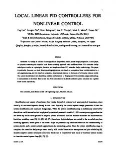
1. Event Output (Alarm / Status ) & DO Output Event Output The number of EV outputs : Total 3 points EV1 to EV3 EV output rating : Contact output 240V AC / 1.0A (resistive load) DO Output The number of DO outputs : Total 5 points DO1 to DO5 DO output rating : Open collector output 24V DC / 50mA max. In the event action and DO action mode, there are the following 19 events which are possible to monitor. In this screen, events selected from them are assigned to event and external outputs. Types of Events (1) DEV High : Higher limit deviation value action (2) DEV Low : Lower limit deviation value action (3) DEV Outside : Action outside higher / lower limits of deviation (4) DEV Inside : Action inside higher / lower limits of deviation (5) PV High : PV higher limit absolute value action (6) PV Low : PV lower limit absolute value action (7) SV High : SV higher limit absolute value action (8) SV Low : SV lower limit absolute value action (9) Auto tuning : While auto tuning in action (10) Manual : While manual control in action
ON ON
(11) Remote : While remote control in action (12) Run : While ramp control in action (13) Stand-by : While control action is off (14) Scale Over : When PV and REM get out of range (15) PV Scale Over : When PV get out of range (16) REM Scale Over : When REM get out of range (17) Direct : During direct output (18) HBA : During output of heater break alarm (option) (19) HLA : During output of heater loop alarm (option)
ON ON ON ON ON ON ON ON ON
See the diagrams below. (1)~(8) (1) DEV High
(2) DEV Low
ON
ON
OFF PV HIGH LOW
(3) DEV Outside ON
OFF
ON
OFF
OFF
(4) DEV Inside ON ON
OFF
Notes:
OFF
All the event output signals of the SR253 Series are now optional functions. For details, refer to the ''Note'' of ordering information.
: SV value
: Action set value Type of event
(5) PV High
(6) PV Low
(7) SV High
(8) SV Low
ON
ON
ON
ON
OFF
OFF SV LOW HIGH
OFF
EV 2
EV 3
DEV High DEV Low Scale Over HBA (When HB is equipped) Initial Value
OFF PV HIGH LOW
EV 1
—
—
—
—
DO 1
DO 2
DO 3
DO 4
DO 5
Auto Tuning
Manual
Remote
RUN
Stand-by
2. External Input (Setting of DI assignment) DI input The number of DI inputs : Multi SV selection 4 points, control inputs 4 points (Total 8 points) DI input type : Exclusive use for multi SV selection (binary input) Selectable setting from 8 types: NOP, AT, MAN, REM, STOP, STBY, DA, DIR DI input rating : Non-voltage contact, or open collector input External control For the purpose of carrying out external control by means of no voltage contact signals externally, actions to be executed can be selected from the following 8 types and may be assigned to DI1 through 4. Type Nop Manual Remote Auto Tune Stand-by Dir Act. Stop Direct
Description of action Not in operation Switching control output between auto and manual (ON: Manual) Setting REM SV / changing LOC SV setting (ON: REM SV set) Switching ON / OFF of AT (ON "edge": AT execution) Switching execution / pause of control (ON: pause) Switching direct / reverse action of output characteristics (ON: Direct action) Switching pause / restart of ramp control (ON: Pause in ramp control) (Only during execution of ramp control) Switching ON / OFF of EV and DO output (ON: EV and DO outputs ON)
When not in operation Signal detection ------Level AT, STB Level AT Level MAN, STB, RUN, REM Edge None Level AT, RUN Level -------
Level
None
Level
ADDITIONAL FUNCTIONS (OPTIONAL)
Series
Example of use: Actions assigned from outside the instrument can be controlled when switch is connected to external input / output 24-pin plug Nos. 12 (COM), 11 (DI 1), 10 (DI 2), 9 (DI 3) and 8 (DI 4) and contact signals are applied.
SR253 I / O 24-pin plug
DI-COM DI1 DI2 DI3 DI4
SR253
12 11 10 9 8
Selection of local SV No.: Local SV No. can be selected by external input. In order to use this function, you have to select EXT Setting of selections / switch of multi-SV No. to light the ESV lamp in the front panel. Example of use: SV No. can be selected from outside the instrument when 24-pin plug for external input / output (an accessory to this instrument) is used and BIN code digital switch is connected to pin Nos. 12 (COM), 7 (SEL1), 6 (SEL2), 5 (SEL4) and 4 (SEL8). For 24-pin plug and BIN code digital switch (multi-SV No. switching device), see external input / output plug accessories. If you do not have BIN code digital switch, select SV No. by applying contact signals to 24-pin plug terminals as shown in the following table. When SV No.5 is to be selected: Short across pin Nos. 12 (COM), 7 (SEL1) and 5 (SEL3). SR253 I / O 24-pin plug
SV-COM SV-SEL1 SV-SEL2 SV-SEL4 SV-SEL8
SV No.
Pin No.
12 7 6 5 4
1
2
3
4
5
6
7
8
9
10
No.7 (SEL 1) No.6 (SEL 2) No.5 (SEL 4) No.4 (SEL 8) The
mark shows shorting between the pin No. and COM
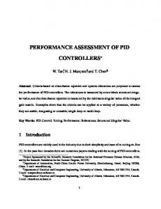
APPLICATION EXAMPLE Cascade Control
Ramp Control Recorder SR253
SR253 M
RTD1
Raw Material
Setting Switch (10 max.)
RTD2
(BIN) PV Transmit
Control Signal SR253 (2-output type)
400 T/C
RAMP
300 Cooling Jacket 1
2
10
RAMP
200 RAMP 100 PAC
Water
SV1
Heater Regulating Valve Timer+ Relay Sequence
Three-zone Control Slave
Slave
SV OUT SR253
SV4
Monitor Control
Master
REM
SV3
RAMP 1~9999 or 0.1~999.9 ˚C (˚F) Time: Min. or Sec.
Electric Oven
Steam
SV2
Personal Computer
REM SR253
SR253 RS-422A SR253
PAC
PAC
PAC
Thyristor
Thyristor
Thyristor
T / C2
T / C1
SR253
SR253
T / C3 PAC
PAC T / C1
Heater Electric Oven
SR253
Heater
PAC T / C2
PAC T / C3
T / C4
ORDERING INFORMATION ITEMS SERIES
Series
CODE SR2531 2
INPUT
3 4 6 YI-
CONTROL OUTPUT 1
PVN-
CONTROL OUTPUT 2 (HEAT/COOL CONTROL) (OPTION)
YIPV-
EVENT OUTPUT/HEATER BREAK ALARM (OPTION) *FOR H. B. ALARM, SELECTABLE ONLY WHEN CONTROL OUTPUT 1 IS Y OR P
REMOTE INPUT (OPTION)
ANALOG OUTPUT (TRANSMISSION) (OPTION)
0 1 2 3 06 04 05 14 15 16 00 13 14 16 23 24 26 0
EXTERNAL INPUT AND OUTPUT CONTROL SIGNAL (OPTION)
INTERFACE FUNCTION (OPTION)
REMARKS
1 2 0 5 6 7 0 9
SR253
SPECIFICATIONS MPU-Based PID Auto-Tuning Controller, DIN 96 × 96 mm Thermocouple, User-selectable inputs and ranges R.T.D. (Pt100), User-selectable ranges DC Voltage, User-selectable 0~10, 10~50, 0~20, 0~50, 0~100, -10~10, -100~100mV linear inputs and ranges DC Current, User-selectable 4~20, 0~20mA linear inputs and ranges DC Voltage, User-selectable 0~1, 1~5, -1~1, 0~2, 0~5, 0~10, -10~10V linear inputs and ranges Contact: PB Cycle 1~200 seconds variable, Capacity: 240V AC 2.5A / Resistive load, 1A / Inductive load Current: 4~20mA DC, Load resistance: 600Ω max. (Factory set=RA) SSR Voltage: PB Cycle 1~200 seconds variable, Output rating: 12±1.5V DC / 30mA max. Voltage: 0~10V DC, Maximum load current: 2mA max. (Factory set=RA) None (Select one output model) Contact: PB Cycle 1~200 seconds variable, Capacity: 240V AC 2.5A / Resistive load, 1A / Inductive load Current: 4~20mA DC, Load resistance: 600Ω max. (DA) SSR Voltage: PB Cycle 1~200 seconds variable, Output rating: 12±1.5V DC / 30mA max. Voltage: 0~10V DC, Load current: 2mA max. (DA) None Event contact output - 3 points Event contact output - 3 points + heater break alarm (heater current 30A) Event contact output - 3 points + heater break alarm (heater current 50A) 0~10V DC, Input resistance: 500kΩ min. (Non-Isolated Input) 4~20mA DC, Receiving resistance: 250Ω 1~5V DC, Input resistance: 500kΩ min. 4~20mA DC, Receiving resistance: 250Ω (Isolated Input) 1~5V DC, Input resistance: 500kΩ min. 0~10V DC, Input resistance: 500kΩ min. None 1-Output, Voltage: 0~10mV DC / Output resistance: 10Ω 1-Output, Current: 4~20mA DC / Load resistance: 300Ω max. 1-Output, Voltage: 0~10V DC / Max. load current: 1mA max. 2-Output, Voltage: 0~10mV DC / Output resistance: 10Ω 2-Output, Current: 4~20mA DC / Load resistance: 300Ω max. 2-Output, Voltage: 0~10V DC / Max. load current: 1mA max. Without With: 24-pin plug and socket only. Select (SV1~SV10), input (DI1~DI4) and output Open collector (DO1~DO5). With: 24-pin plug w/1-meter wire. Select (SV1~SV10), input (DI1~DI4) and output Open collector (DO1~DO5). Without RS-485 RS-422A RS-232C Without With (Please consult before ordering.)
Notes: 1. All the event output signals of the SR253 Series are now optional functions. 2. For example : a. If the open collector output signal (DO1-DO5) of the events is required, Select (0) of Item 5 and then (1) or (2) of Item 8 in the Ordering Information table. When (0) of Item 5 and (0) of Item 8 of the Ordering Information table are selected, the connector (24-pin plug) for open collector output signal is not attached and therefore, no open collector output signal is produced. b. If the even contact output signal (EV1-EV3) is required, select (1) of Item 5 and then (0) of Item 8 in the Ordering Information table. c. If both an event contact output signal (EV1-EV3) and the open collector output Signal are required, select (1) of Item 5 and then (1) or (2) of Item 8 in the Ordering Information table.
STANDARD RANGE & USER-PROGRAMMABLE SCALING
Series
SR253
Since the Series SR253- has been designed for user-selectable inputs, user-selectable ranges and user-programmable scaling, the unit will be shipped with one factory-set standard range. If a range selection other than the standard is required, user-selectable inputs (T/C's) and user-selectable ranges (T/C's & RTD) are available as listed below. Standard Range (Factory-Set when shipping) Input 1 Thermocouple 2 R.T.D. 3 DC Voltage 4 DC Current 6 DC Voltage
Standard / Rating (K) Pt100 0~10mV 4~20mA 0~10V
User-Programmable Scaling (Current or Voltage)
Ranges 0.0~800.0˚C 0.0~200.0˚C 0.0~100.0% 0.0~100.0% 0.0~100.0%
Range No. Voltage (mV) Current (mA) 1 -10~ 10 – 2 0~ 10 – 3 0~ 20 – 4 0~ 50 0~20 5 10~ 50 4~20 6 0~100 – 7 -100~100 –
Voltage (V) -1~ 1 0~ 1 0~ 2 0~ 5 1~ 5 0~10 -10~10
*1
User-Selectable Range (Thermocouple) Range Type of No. Input 1 B 2 R 3 S 4 K 5 K 6 K 7 K 8 K 9 E 10 J 11 T 12 N 13 PL II 14 PR40-20 15 WRe5-26 16 U 17 L 18 K 19 Gold iron / chromel
˚C 0.0 ~ 1800.0 0.0 ~ 1700.0 0.0 ~ 1700.0 -100.0 ~ 400.0 0.0 ~ 400.0 0.0 ~ 800.0 0.0 ~ 1200.0 -200.0 ~ 200.0 0.0 ~ 700.0 0.0 ~ 600.0 -200.0 ~ 200.0 0.0 ~ 1300.0 0.0 ~ 1300.0 0.0 ~ 1800.0 0.0 ~ 2300.0 -200.0 ~ 200.0 0.0 ~ 600.0 – –
Measuring Range ˚F 0 ~ 3300 0 ~ 3100 0 ~ 3100 -150.0 ~ 750.0 0.0 ~ 750.0 0.0 ~ 1500.0 0.0 ~ 2200.0 -300.0 ~ 400.0 0.0 ~ 1300.0 0.0 ~ 1100.0 -300.0 ~ 400.0 0.0 ~ 2300.0 0.0 ~ 2300.0 0 ~ 3300 0 ~ 4200 -300.0 ~ 400.0 0.0 ~ 1100.0 – –
K – – – – – – – – – – – – – – – – – 10.0 ~ 350.0 0 ~ 350.0
Initial value: Range No.6 (K thermocouple 0.0~800.0˚C) Note 1: In the case of B thermocouple, accuracy is not guaranteed at temperatures below 400˚C (750˚F). Note 2: The precision for PR40-20 is ±(0.3% FS+1˚C) Note 3: The precision for K thermocouple (Kelvin) is: 10.0~ 30.0 K : ±(0.75% FS+1K) 30.0~ 70.0 K : ±(0.30% FS+1K) 70.0~350.0 K : ±(0.25% FS+1K) Note 4: The precision for the gold iron / chromel thermocouple is ±(0.25% FS+1K)
User-Selectable Range (R.T.D.) Range No. 1 2 3 4 5 6 7 8 9 10 11 12 13 14 15 16
Type of Input Pt100 (JPt100)
-200.0 -200.0 -100.00 -100.0 -100.0 -60.00 -50.00 -40.00 Common to -20.00 Pt100 and JPt100 0.000 0.00 0.00 0.0 0.00 0.0 0.0 Pt100 0.0 (JPt100) 0.0
Measuring Range ˚C ~ ~ ~ ~ ~ ~ ~ ~ ~ ~ ~ ~ ~ ~ ~ ~ ~ ~
600.0 500.0 100.00 100.0 300.0 40.00 50.00 60.00 80.00 50.000 50.00 100.00 100.0 200.00 200.0 300.0 500.0 500.0
-300.0 -300.0 -150.0 -150.0 -150.0 -80.0 -60.00 -40.0 0.00 0.00 0.00 0.00 0.0 0.0 0.0 0.0 0.0 0.0
˚F ~ 1100.0 ~ 900.0 ~ 200.0 ~ 200.0 ~ 600.0 ~ 100.00 ~ 120.00 ~ 140.00 ~ 180.00 ~ 120.00 ~ 120.00 ~ 200.00 ~ 200.0 ~ 400.0 ~ 400.0 ~ 600.0 ~ 1000.0 ~ 900.0
Initial value: Range No.14 (Pt100 0.0~200.0˚C) Note 5: The precision of 50˚C (120˚F) span input is ±0.2% FS.
*1 Initial value: Voltage (mV) input; Range No.2 (0-10mV) Current (mA) input; Range No.5 (4-20mA) Voltage (V) input; Range No.6 (0-10V)
EXTERNAL INPUT / OUTPUT PLUG ACCESSORIES Relay Unit Model AP2MC for converting contact output into open collector output
Series
SV No. Selector Model KA251 for selecting SV1~SV10 BIN cord
SR253
24-pin Plug Cord Model CA2530-01 with crimp terminal shielding wire and mark band (1m)
ACCESSORIES REQUIRED FOR HEATER BREAK ALARM FUNCTION (COMMON) • CT wiring
• 30A (CTL-6-S)
• 50A (CTL-12-S36-8) 30
2.8
To CT Input terminal
2.36
9
7.5
15
12
40
3
10.5
25
5.8
10
21
12 2- 3.5 15
30 40
2-M3 30
7.5
Heater (load) wiring
40
(Unit: mm)
EXTERNAL DIMENSIONS & PANEL CUTOUT (55)
138 96
13
125
When I / O connector lead is attached.
(5) When terminal cover is attached.
ST SY RUN ESV REM COM EV1 EV2 EV3 DO1 DO2 DO3 DO4 DO5 AT MAN 0UT1
PV OUT2
96
˚C
DISP
SR253
GRP
SCRN
ENT
SH I MADEN
130min
92
130min
92
PANEL CUTOUT 92(H) x 92(W) (+0.8 / -0mm)
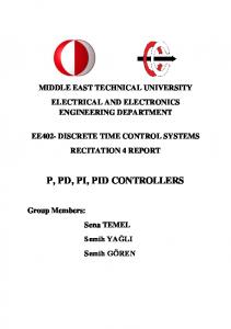
TERMINAL ARRANGEMENT
Event output (Option)
Series
SR25301
Analog output(Option) Remote setting input
A-output2
4
Input Current or voltage input
5
EXTERNAL I/0
2 3
19
COM
10
L
20
EV1 1A 240V AC
11
N
21
1A 240V AC
22
1A 240V AC
EV2
A
7
7
A
COM
23
B
9
9
B
6
24
7
RS–232C RS–422A RS–485
7 8
B
8
B
9
DC
10
13
NO
14
NC
15
11
OUTPUT1 4–20mA DC 0–10V DC 30mA 12V DC
12
2.5A 240V AC
CON
16
NO
17
NC
18
OUTPUT2
Control output
2.5A 240V AC
Relay contact output
13
COM
13
14
NO
14
15
NC
External contact input
24 DO-COM
SV, DI-COM 12 DI 1 11
Relay
23 DO 1
Relay
22 DO 2
Relay
21 DO 3
DI 3
Relay
20 DO 4
DI 4 8 SV SEL 1 7
19 DO 5
Diode (for protection of internal transistor) Rating: 100V 1A
Output 2
DI 2 10 9
SV SEL 2 6 Maximum 50mA, Maximum 24V DC
SV SEL 4 5 SV SEL 8 4
Current output Voltage output SSR drive voltage output
Output 1
External input / output 24pins (Option)
Relay
For grounding
4–20mA DC 0–10V DC 30mA 12V DC
9
Open collector output
Free supply 100~240V AC
12
CT
R.T.D.input
100 – 240VAC~ 50/60Hz15VA
EV3
REM
TC input
Power supply
!
1 A-output1
SR253
16
COM
16
17
NO
17
18
NC
BIN CODE Heater break alarm, CT Input terminals (Option)
Warning • The SR253 series is designed for the control of temperature, humidity and other physical values of general industrial equipment. (It is not to be used for any purpose which regulates the prevention of serious effects on human life or safety.) Caution • If the possibility of loss or damage to your system or property as a result of failure of any part of the process exists, proper safety measures must be made before the instrument is put into use so as to prevent the occurrence of trouble.
ISO 9001 (The contents of this brochure are subject to change without notice.)
Temperature and Humidity Control Specialists
Head Office: 2-30-10 Kitamachi, Nerima-Ku, Tokyo 179-0081 Japan Phone: +81-3-3931-7891 Fax: +81-3-3931-3089 E-MAIL:
[email protected] URL: http://www.shimaden.co.jp
01ESR253 0230