MYGEN : Automata-Based On-line Test Generator for Assertion-Based Verification Marc Boulé, Zeljko Zilic
Yann Oddos, Katell Morin-Allory, Dominique Borrione
McGill University Montréal, Québec, Canada
TIMA Laboratory, Université Joseph Fourier Grenoble, France
[email protected],
[email protected]
[email protected]
ABSTRACT
its quality critically depends on the thoroughness of both the system specification and the test sequences. A good specification should be mechanically interpretable in test scenarios, in order to ascertain that it correctly portrays the designer’s intent. It should also be used in a wide variety of verification tools, all along the design and verification flow. Lots of progress in empowering designers to provide thorough specification has been recently achieved through the Assertion-Based Verification (ABV) paradigm [6]. In ABV, the essential logic and temporal properties of the design and its environment are expressed in a declarative form, using a formal property description language. At any time the properties can be added to the design description, or separately linked for emulation, simulation or model checking purposes. Two IEEE standards are mainly used to write temporal properties: PSL (Property Specification Language) [7] and SVA (SystemVerilog Assertions) [14]. In the following, all the properties are written in PSL, but our method applies to SVA as well. As an example, consider the following PSL property P1:
To assist in dynamic assertion-based verification, we present a method to automatically build a test vector generator from a temporal property. Based on the duality between monitors and generators, we have extended the monitor generator tool MBAC to produce synthesizable on-line generators. We have tested the resulting generators in simulation and by emulation on an FPGA. The combination of multiple generators provides an efficient way to model the environment of modules within a DUT, facilitating an equivalent of software “unit testing” under real conditions, early in the design flow.
Categories and Subject Descriptors B.2.3 [Reliability, Testing, and Fault-Tolerance]: Error-checking— Test generation; B.5.2 [Design Aids]: Verification
General Terms
Property P1 : always (Start → Req until Ack )
Verification
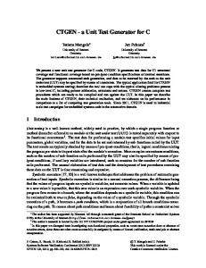
Property P1 states: for each cycle where Start is 1, a request Req should be produced and maintained active (Req=1) as long as the acknowledge signal Ack is not active (Ack =0). The trace on Figure 1 satisfies property P1. Signal Start is active at cycle ]1 and Req is fixed to 1 during the same cycle. Then Req remains active up to ]7. At ]8, signal Ack takes value 1. After this cycle, all the constraints have been satisfied and the trace complies with P1.
Keywords Test vector generation, semi-formal verification, PSL, generator
1.
INTRODUCTION
Guaranteeing that a state-of-the-art system on chip (SOC) is exempt from design errors is a daunting challenge. Most emphasis is put on advancing the technology and improving the design methods. The relentless increase in the number of logic elements that can be placed on a single chip, combined with platform-based design, IP reuse, and design at higher abstraction levels, drive the complexity and performance increase exhibited each year. At the same time, despite significant progress in formal and dynamic verification techniques, the gap between the design and verification capabilities widens. Dynamic verification, featuring simulation and/or emulation, remains the only viable solution for checking complete systems, but
Start Req Ack 1
2
3
4
5
6
7
8
9
Figure 1: A trace satisfying property P1
Temporal properties are divided into two sets: assertions and assumptions. Assertions are used to specify functional aspects of the design under test (DUT). Assertions can be turned into monitors that check if the design is compliant with corresponding properties. Assumptions are used to constrain the behavior of the environment, which is very useful in restricting the generators of possible DUT input vectors. By avoiding non-compliant test vectors,
Permission to make digital or hard copies of all or part of this work for personal or classroom use is granted without fee provided that copies are not made or distributed for profit or commercial advantage and that copies bear this notice and the full citation on the first page. To copy otherwise, to republish, to post on servers or to redistribute to lists, requires prior specific permission and/or a fee. GLSVLSI’09, May 10–12, 2009, Boston, Massachusetts, USA. Copyright 2009 ACM 978-1-60558-522-2/09/05 ...$5.00.
75
the overall dynamic verification can be significantly faster, without impacting its quality. While the verification with the help of assertions is widely supported in current model checkers (RuleBase, FormalCheck, etc.) and simulators (ModelSim, NCSim, etc.), modeling the environment of the DUT with formal assumptions is less widespread. In this paper, we focus on the following problem in dynamic verification: how to automatically build an executable model of the environment, which generates test vectors that satisfy all assumptions about the environment. We present a simple method by which each assumption is first transformed into an efficient automaton, which is then turned into a synthesizable test generator. Please note that the main outcome here is an on-line test generator, which facilitates a high-throughput simulation/emulation when embedded with DUT, with no need for a separate test generation procedure. The overall scenario that this outcome facilitates is as follows: starting with a HDL description of a design and the properties expressed in PSL, we provide a self-certifiable system, consisting of a test generator and the property monitors sufficient to check whether the properties are maintained across all self-generated test cases. The test generation and error reporting are well compacted: all that is needed is to check whether assertion monitors fire, signaling a failure. This scenario can be applied for testing modules (i.e. unit testing), or for complete designs, to improve verification productivity and quality. Section 2 gives a brief overview of different approaches used to improve the quality of test vectors, by modeling the environment of the DUT at different levels. Our approach is described in section 3. The construction time and synthesis results on FPGA are given in section 4. Finally section 5 concludes on the method and its future extensions.
2.
crease the test coverage during simulation. From assertions on the design under test, the method produces satisfying test vectors without vacuity. The underlying formalization is a game between the environment and the DUT. Three different methods are defined depending on the level of observability and controllability of the signals involved in the assertion. In contrast to all the above previous work, our approach only relies on the property formulas, and not on the DUT, to generate test vectors: PSL properties are synthesized into hardware modules that generate compliant signals. The same applies to the concept of “cando objects” [5], except that their solution is technically very different and oriented towards model checking rather than on-line execution; in particular, they do not support arbitrary repetition (’+’ and ’*’) operators. In [9], the HORUS tool has been developed to produce synthesizable and low complexity test vector generators from temporal properties. The idea is to define a library of primitive components (one for each PSL primitive operator), and an interconnection scheme to build a generator for a complex property. The method presented in this paper is the result of a cooperation between the groups that developed MBAC and HORUS. The motivation was to benefit from the efficiency of MBAC in automata processing [3], and the duality between language generation and recognition, to unify the construction of generators and monitors.
3.
GENERATORS WITH MYGEN
3.1
Preliminaries
Building Checkers from Properties. The MBAC tool takes as input a temporal property and produces a monitor for a given PSL property [3]. To achieve this goal, it builds a non-deterministic automaton that recognizes all the traces that violate the property. Then, the automaton is transformed into a synthesizable RTL checker. Basic automata have been defined for a kernel of primitive PSL operators. The remaining operators are translated in terms of the kernel, using rewrite rules. These rewrite rules have been proven correct with respect to the PSL semantics, using the PVS theorem prover [8]. Complex properties are turned into a monitor in two steps: apply rewrite rules as necessary, and combine basic automata to obtain the final automaton for the checker. Automata and logic optimizations are performed to minimize the size of the final checker. The right part of Figure 2 depicts the automaton produced by MBAC for the following property P2:
STATE OF THE ART
In the context of logic simulation and logic testing, a wide range of methods have been proposed to replace pure random test sequence generation by smaller, more focused sequences. Recently, assertion-based verification has renewed the interest in constrained test generation. A first approach found in [15] applies the divide and conquer principle: the design is sliced into smaller components. Each one is used to extract constraints which are recombined to get the constraints for the whole design. Test vectors are obtained by analyzing these global constraints. Combined with an Automatic Test Pattern Generator (ATPG), all the random sequences not compliant with the interface specification are deleted, thus increasing the test efficiency. An early method to produce test vectors compliant with a set of temporal properties combines the design with external blocks (one in Verilog and one in C) which dynamically constrain the inputs of the design [13]. The main drawback is the lack of expressive power due to the use of only one operator. An automata theoretic approach is presented in [4]. Two automata are extracted from the system and the property, and the product automaton is constructed. State space traversal techniques are used to extract test vectors that lead to a failure. The method can suffer from a state explosion in the resulting product automata. A two-step method is described in [11]. First, random vectors are applied, and the registers and wires that seldom or never change value are identified. Second, “input cubes” are computed, specially aimed at reaching these identified elements. The experimental results show very good test coverage results on small cases, but this gate-level approach may become complex on large circuits. A black-box approach is presented in [10]. The goal is to in-
Property P2 : always (sig1 → next sig2) Transitions are labeled with conditions, i.e. Boolean expressions built over a combination of the signals involved in the property. Each combination of an active state and input condition is evaluated to determine which next states are to be activated. The automaton then transitions into a new set of active states, and the process repeats at each clock cycle. Each time a final state is active, the property has failed and a counterexample trace can be analyzed. Two different modes are used in MBAC to treat a property. A Boolean or sequence appears in two different semantic contexts, depending on how it is used in a property [3]: • Obligation mode: Expression for which the failure of a sequence or Boolean expression must be identified. The automaton must match a Boolean expression or sequence when it fails to occur.
76
• Conditional mode: Expression for which the detection of a sequence or Boolean expression is required.
avoiding its application, we obtain the set of all the traces compliant with the property. The implementation in MBAC is actually more involved, and requires particular modifications to algorithms for operators such as “until” and “before”.
For example, in a property implication with two sequences (s1 |–> s2 ), a successful detection of s1 enforces the obligation that s2 must be matched, hence the two modes described above. The obligation mode version of a sub-automaton is obtained from the typical conditional mode automaton by applying an algorithm called First_Fail. For the P2 example, Figure 2 illustrates how the second transition leads to a failure of the property (right side of figure). If at a cycle n, sig1 is active, then the property fails if at cycle n+1, sig2 is false. In the general case for more complex properties, First_Fail may modify the structure of the automaton. true
3.3
Description of the Generator Automaton. All generators have a generic interface. They take as inputs the synchronization signals clk and reset. Their outputs are composed of all the signals involved in the corresponding property. The HDL description is composed of two blocks: one modeling the generator automaton and one used for pseudo-random number generation. As more than one state can be active during the same cycle, one flip-flop is used for each state. The HDL process for the FA block always has the same structure:
true
S2
S0
S0
S2
1. Selecting active states (line 1 of the HDL code in Figure 5);
First_Fail sig1
S1
sig2
Initial FA
sig1
S1
!sig2
2. Selecting outgoing transition(s) for the current active state (lines 2, 4 and 8);
Monitor FA
3. Selecting values of output signals for the current transition (lines 9, 14, 18).
Figure 2: Monitor and Generator Finite Automata (FA)
In every terminal branch of the automaton code (lines 3, 10, 15 and 19 in Figure 5), two types of actions are performed: output signal assignments, and activation (resp. deactivation) of destination (resp. source) states.
From Monitors to Generators. Generators and monitors are dual concepts: a monitor recognizes the complement language1 of a property, while a generator produces the language of the property. This symmetry is depicted at the automaton level in Table 1. Since the monitors built by MBAC are of low complexity and efficient in emulation, we reuse the MBAC approach and automaton construction mechanism to produce synthesizable generators.
Random Numbers. Several traces can satisfy the same property. Therefore, more than one path may lead to a final state verifying the property: there exist some states where a choice among several possible outgoing transitions has to be made. A pseudo-random block is used to randomly choose one transition. The pseudo-random component is not only used to select a transition. Given a transition, its associated condition can be a complex Boolean expression, involving several signals: more than one valuation for the signals can satisfy the condition. The choice between these valuations is carried out by the pseudo-random block. Two different kinds of random number generators were tested : Linear Feedback Shift Registers (LFSR), and specific Cellular Automata (CA) [16] suitable for random number generation such as CA30. CA are more efficient in terms of synthesis and random quality [12], but their characterization is complex and actually still incomplete. The random block can be parameterized to modify the quality of the traces produced by the generator. Moreover, it is possible to build a generator using different modes provided by our tool. This enables more precise control over the kind of test vectors that are to be generated:
Table 1: Symmetry between Monitors and Generators Monitors Generators transitions’ labels observed generated final states failure satisfaction without vacuity
3.2
Construction of a Generator
Global description. Figure 3 illustrates the steps required to build a generator from a property. First, the MBAC tool is run in generator mode and elaborates the generator automata as opposed to checker automata. Generators machines produce accepted traces for the property, as opposed to monitor automata which mark assertion failures. Finally, the synthesizable HDL description for the generator is extracted.
• SimpleRand: simple random generation shares the random component for different tasks (selects transitions for all the states, defines the random value of the signals etc...). The quality of the resulting traces is low due to the dependencies induced by this sharing of the random block; however, it can be useful for “quick-prototyping” on a small platform.
MBAC-generator. The basic idea is to avoid the application of the First_Fail algorithm. The resulting automaton describes all the traces compliant with the corresponding property. This effect can be observed in Figure 2. The underlying concept is that the First_fail applies a form of negation on a portion of the automaton. This algorithm gives the set of all the traces not compliant with a property. By 1
The Generator
• DirRand: directed random generation allows the selection of the length of test vectors such as: shortest, short, medium, long etc... It can be used for an in-depth test of the design.
In dynamic verification, this is actually not the exact complement.
77
PSL property always (Start → Req until Ack )
MYGEN
Generator HDL
!c
Back−End
1
c
MBAC
0
a
!a | c
Clk
Reset
BoolSolve
2
Random
GENERATOR a&b
TransVHDL 3
Ack Req Start
Generator FA
Figure 3: The Generator Flow - Embedding of MBAC into MYGEN
• RealRand: realistic random generation uses a distinct random block for each choice to be made in the FSM. The quality of test vectors is maximal and the generator covers all the set of traces complying with the corresponding property. This is particularly suitable for a complete test without excluding any possible corner case, at the cost of a significant overhead in generator size.
A Trans(0)
S1
The flexibility provided by these different modes is useful, because it allows the creation of different instances of the same generator, each one dedicated to a different step in the test phase. Let “random register” denote a register containing pseudo-randomly generated numbers. For the selection of the transitions, the random registers are denoted Trans. This is illustrated Figure 5 in lines 2, 4 and 8.
A or B Trans(2)
C
S2
S3 Trans(1)
Figure 4: Part of a Generator FA
BoolSolve. For each transition, the generator must produce a combination of signals validating the condition’s transition. It is possible that several signals satisfy the condition. To enumerate all these possibilities and put them into the HDL description, a Boolean solver is used. We use a simple and freely available tool called BoolSolve [1]. It takes as input a Boolean expression (the condition’s transition in our case), and provides all the correct valuations of signals for this expression. All these possibilities are written into the HDL description. The random registers Rand are used to randomly select one of these valuations as it is shown in the HDL code in Figure 5, in lines 9 and 14. All the other signals (those not involved in the current condition’s transition) have a random value.
1. if S1=1 --Current State=S1 2. if Trans(0)=1 --Cond=A 3. A