Automated Configuration of Parametric Feeding Tools for Mass Customization. Ajay Joneja and Neville K.-S. Lee. Dept of Industrial Engineering & Engineering ...
Automated Configuration of Parametric Feeding Tools for Mass Customization This is the Pre-Published Version Ajay Joneja and Neville K.-S. Lee Dept of Industrial Engineering & Engineering Management Hong Kong University of Science & Technology
Abstract Mass customization is a dominant new trend in modern manufacturing, whereby industries are required to produce umpteen variations of products at costs approaching those achievable in mass production. Among the methods to tackle this demand is development of flexible tooling which operates at high throughput rates. A suite of such tools called MPATS (a Modular, Parametric, Assembly Tool Set) is developed for this. The paper introduces MPATS, and also describes a computer-aided planning system to automatically configure MPATS. Keywords: mass customization, flexible tooling, geometric reasoning
1. Mass Customization Mass customization is a trend that is being followed unequivocally by many modern industries. There are many products where the competitive edge of the producer is dependent not merely on the price, but also on the choices or variations provided in each product line to cater to individual customers’ tastes. Examples of such product range from automobiles (manifested by the increasing number of “options” available in any base model of a car) to electronic products such as computers. The challenge it creates is that of producing an increasing variety of products of a family without a significant trade-off in production costs or lead time. In most conventional production units, each change of product lines (to switch products) calls for significant down times, reprogramming of flexible automation equipment, re-tooling of hard automation, and sometimes re-training of personnel. While modern industry is grappling with the implementation of methods to face this need, not much academic research has been reported, nor any systematic study made of the related engineering issues. There are two fundamental avenues which can help the modern assembly facility to produce, at a high rate, such diversity of product types. (a) Product Design Methodology These methods, called Design for Mass Customization [Tseng 96], propose that the design of modern products must be guided by considerations which aid efficient manufacturing of product variants. Tseng et al. have proposed maximizing modularity in design to achieve this. Based on this idea and Suh’s axiomatic approach [Suh 90], they develop a Product Family Architecture as a design basis. (b) Manufacturing Methods The other approach is to study the design of the assembly process, and product assembly lines. The motivation is to design manufacturing systems that will operate at high throughput rates. At the same time, these assembly systems will provide a limited flexibility which allows for very fast turnarounds to change products within the family. We can study the manufacturing problems at two levels: (i) Assembly line level: determination of equipment to be provided at each workcell, in order to foster quick turnaround; and
(ii) Equipment level: Redesign of equipment/hardware in order to allow rapid turnaround. This paper focuses on the latter of these two. Typical assembly system hardware can be classified into the following categories: transfer and conveying devices (indexing machines, belts), powered or manual tools (drills, screwdrivers), passive tools (jigs and fixtures), programmable tools (robots) and feeding devices. This research proposes the use of parametric, modular hardware as a method of achieving adaptable assembly lines required for mass customization. In order to maintain focus, the research will concentrate on that subset of the above categories which currently has the least flexibility in terms of adaptation to variations in part geometry. These are mainly some types of transfer devices, and almost all varieties of feeding and orienting devices. The idea of modular equipment is not new, and has proven its popularity in specific applications. Primary among these are modular fixtures which have been successfully used in machining as well as assembly systems. Other forms of reconfigurable, or flexible fixtures have also gained some level of popularity [Joneja 93 has a survey]. However, most devices used for feeding of mechanical components, especially small components, are still fixed in design. An outstanding amount of research and innovation in this particular area came in the last two decades from Boothroyd and his group [see Boothroyd 91 for a comprehensive coverage]. However the idea of modularity, or parametric variability is not seen in current devices. In current practice, the assembly engineer provides samples of the parts to the supplier of the feeding devices, who then designs specialized feeding devices and manufactures them. Some initial pioneering work in making these designs more flexible has been reported by Lim et al [Lim 93], who developed hardware modifications on bowl feeders which allow some parametric changes on various modules. Their group has also reported a knowledge based system for automated module selection and sequencing to assist in feeder design for prescribed parts [Tan 95]. Our research independently developed some designs for similar goals. While some applications overlap with the above work, the MPATS project aims for a broader application area. The methodologies for the planning automation are also significantly different, and will perhaps be of interest to industries looking for alternate solutions.
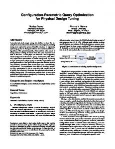
2. A Modular, Parametric Assembly Tool Set (MPATS) The MPATS project aims to design and develop several classes of modular, parametric hardware which can assist in designing of quick turnaround assembly lines. All the initial implementations focus on small part assembly automation and handling, with operations including orienting, feeding, transport and assembly. The classes and the designs are briefly introduced in the following sub-sections: 2.1. Fixtures Several versatile fixtures have been developed and are popularly used in different manufacturing operations [Gandhi 85]. Further, many researchers, including our group, have developed automatic fixture planning systems [Chou 93, Markus 88, Sakurai 90, Trappey 93]. Our planner [Joneja 93] is a feature based system which uses geometric methods create fixture assemblies involving modular fixtures and/or vises to hold prismatic parts. The planner uses a built-in solid modeler and a screw theory based restraint analysis system. Modular fixtures are extremely versatile, and with a reasonable sized library, most shapes can be fixtured for various domains, including assembly and machining. 2.1. Vibratory feeders These, and especially bowl feeders, are widely used for orienting and feeding small parts to automatic assembly heads. Figure 1 shows a typical bowl feeder. The final part of the feeder track usually is custom fitted with a set of devices to orient the part being fed. An example of such a set of devices is shown in figure 2, to orient a flat box of fixed size.
Figure 2. Passive and active devices on a bowl feeder (source: Boothroyd 91) To extend its versatility, we have re-designed the traditional bowl feeder. This is done by first modifying the bowl to allow fitting of a standard sized modular base plate which provides several fixturing points for various devices. The modular plate is fitted onto a conventional bowl after cutting away a portion of its side wall and also some length along the last part of the spiral track. The fixturing points are a set of standard sized bevel slots, each providing attachment to one of a set of parametric devices that are used to orient the parts traveling along the track. Typically, three to four such devices are sufficient to handle a given part; therefore, our prototype base plate has four slots. Since each module fitted onto the base is parametric, it can be adjusted in less than a minute to handle a different sized part. Figure 3 shows a view of the solid model of the modified bowl. Figure 4 shows the exploded view of the assembly of the modular base, along with a set of MPATS devices. The configuration shown can be used to feed screws oriented vertically with their heads on top. If a simple modification in the product required slightly different sized screws to be used, the feeder can be adjusted in minutes. Further, to handle a completely different part family, different modules can be fitted, and adjusted equally rapidly.
Figure 1. Traditional Bowl Feeder (source: Boothroyd 91) Figure 3. MPATS bowl feeder
Figure 4. Exploded View: MPATS screw feeding bowl
We are also developing an automatic tool planner, which can generate feeder device configurations to handle different parts. Boothroyd et al. had developed an extensive classification and coding system for various part shapes, which can form the basis for a variant tool planning system. More recently, Tan et al. [Tan 95] used a knowledge based AI approach, with geometric routines to assist their tool planning functions, and broadly following Boothroyd’s methods. We aim to further extend this approach by addition of a generative planner for prismatic parts, with the help of an orienting feature recognition module. The tool configuration planner requires selection and sequencing of the modules. The analysis begins with the solid model of the part. We distinguish between rotational and prismatic parts, since the planning for rotational parts is simpler, without the need for computationally expensive orientation feature recognition. Figure 5 shows two classifications which are used for rotational parts.
resting on the track, perpendicular to the travel. A restraint planner is used to check whether the part is in quasi-stable or natural equilibrium until it reaches the final device. The projection of the part onto each face of the covering box is used to reduce the feature recognition process to a 2D problem. Currently, the features identified include steps, slots and wedges. Each feature identified gives hints about the use of that particular orientation of the part to either install a rejection device, an active device (e.g. an edge riser), or a passive device (e.g. a wall projection). The actual sequence and plan of the devices is based on a simple search strategy, which first matches the devices in the database to their potential use for an identified feature. The search identifies sequences of devices which can effectively constrain the part to only one translational degree of freedom, along the path of motion. The exhaustive search is not inefficient, since the total number of devices that are planned in the system is limited (well below a hundred) and the total number of devices for a part is within four (in our case) or five in general. Figure 6 shows the architecture of the device planning system.
MPATS Bowl Feeder Device Selection & Planning Rotational Parts
Prismatic Parts Minimum box Cover
Shape classify (long, flat) Feature Idnetification
Projected Profiles Along X, Y, Z Feature Recognition Device Selection Sequence Plan
Variant planning w/ Device Parameter Setting Parameter Setting
Feature DB Device DB
Figure 6. Device Planner Architecture Flat (L/D < 1)
Uniform
Fat (L/D - 1)
One-head
Long (L/D > 1)
Two-head
Spindle
Figure 5. Rotational part shapes From the first classification, the device plan for flat and long rotational parts is quite formulaic, based on which shape type from the second set of figures the part belongs to. However, such routine planning cannot be extended to fat parts. We therefore classify fat cylindrical parts as prismatic, and use the prismatic part planner. The approach used for prismatic parts is shown in the figure below. The central idea used is that as the part moves along the track, each subsequent device reduces its degrees of freedom, until the last device only allows the freedom to move along the track. In order to ensure this, a condition which often holds true is that the part projection on a plane perpendicular to its path should be minimum. In order to get this, we have implemented a minimum box cover algorithm based on [O’Rourke 85]. Thus, the preferred final orientation of the part is such that the shortest edge of the minimum covering box is
2.3. Non-Vibratory Feeders Hundreds of different automatic feeders are in common use in industry, each designed for specific part shapes and sizes. Several broad classes of such feeders have been described by Boothroyd, who also identifies the parameters which can be assigned specific values in the particular instance of the designed feeder. We have identified a group of such nonvibratory feeders, and designed parametric variations of these. The initial prototypes include parametric versions of a slotted wheel hopper feeder, a rotary centerboard hopper feeder and a magnetic disc feeder. These designs are currently being tested for viability, and while we have achieved some flexibility, it appears to be at the cost of throughput rates. Also, since most of these modified designs involve purely parametric variations, the modifications to adapt to new part sizes do not require any computer-aided planning. 2.4. Passive transport devices Oriented parts emerging at the mouth of a powered feeder (e.g. a bowl feeder) often need to be transported to a location where the automatic assembly head can pick and assemble them. This transportation is usually along a passive track, along which the parts move either due to gravity, or due to the pressure from the upstream parts in the feeding device. To ensure the completeness of the MPATS system, we are also developing a set of parametric tracks, which could be used to deliver different shapes/sizes of parts between the feeder and the
assembly head by easy modification. The parametric tracks are based on a set of simple extrusions, which can act as guide rails for different shaped parts. The feed tracks are also useful as shape/orientation filters for some non-vibratory feeders, disallowing all parts not in the required orientation from being fed. 2.5. Assembly Tools Finally, the MPATS project is also involved in design of a versatile robot assembly gripper to handle a large variety of small, rigid parts. Flexible grippers of varying complexity have been designed and reported for decades. The most flexible of these are usually multi-fingered, multiple degrees-of-freedom grippers. Our development provides a simple, modular grippers, typically with a single degree of freedom, but with the capability to perform a multitude of simple assembly tasks. The flexibility is realized by programming the robot to automatically change the actuation system, and also the endeffectors, depending upon the task to be performed. Thus, while individual grippers are simple and can do very simple operations, different parts and operations can be handled by changing modules. The concept of the MPATS gripper system is described in the figure below.
Robot Arm Pneumatic supply
Dynamometer
Actuator, with Flexible End Efferctor Adaptor
End Effector Bay 1 Drill set Screw Driver Set
The authors wish to thank Leung Wing Min, Wu Ka Ho and Banna G. Rao, who worked on the development of the MPATS hardware. We also extend our thanks to Prof Mitchell M. Tseng of IEEM, HKUST for his continued support of our research.
5. References Boothroyd, G., Assembly Automation and Product Design, Marcel Dekker, 1991 Chou, Y.-C., “Automated Fixture Design for Concurrent Manufacturing Planning,” Concurrent Engineering: Research and Applications, vol 1, no 4, Dec 1993 Gadh, R., Prinz, F. B., “A Computationally Efficient Approach to Feature Abstraction in Design- Manufacturing Integration,” Journal of Engineering for Industry, vol 117, no 1, 1995 Gandhi, M. V., Thompson, B. S., "Phase Change Fixturing for Flexible Manufacturing Systems," Journal of Manufacturing Systems, vol. 4, no. 1, pp. 29-38, 1985 Lim, L. E. N., et al, “Flexible Vibratory Bowl Feeding Using Modular Orienting Devices,” J. of the Instt. of Engineers, Singapore, vol. 33, no. 4, 1993
Multi-Actuator Adaptor
End Effector
4. Acknowledgments
Actuator Bay Rotary Actuator Linear Actuator
Markus, A., et al. "Strategies for the Automated Generation of Modular Fixtures," Procs Symp on Mfg systems- Design, Integration and Control, ASME Mfg Intl, pp. 97-103, 1988
End Effector Bay 2
O’Rourke, J, “Finding Minimal Enclosing Boxes,” International Journal of Computer and Information Sciences, vol 14, no 3, 1985, pp. 183-199
Two-finger Sets: Flat + Flat Flat + Vertical V slot Flat + Horizontal V slot V slot + V slot
Sakurai, H., Automatic Setup Planning and Fixture Design for Manufacturing, Ph. D thesis, Dept. of Mechanical Engineering, Massachusetts Institute of Technology, January 1990
Figure 7. Flexible Gripper System The robot used in the prototype is an ADEPT™ Scara robot, with an attached 6-axis dynamometer. 3. Conclusions Thus, the MPATS hardware is designed as a broad base of automation devices which can help in rapid turnaround of a standard, high-throughput assembly line to allow quick product changes. Along with the development of the hardware, we are also developing software systems which can assist in the automatic selection and configuration of the devices. The tool planners introduce a range of new and interesting problems in feature recognition. In this paper, we presented some of the initial ideas and results that have proven useful in this effort. Eventually, we plan to enhance the device planner with a differential depth filter [Gadh 95] based feature recognition module, which can recognize more features such as scalloped holes in cup shaped parts. The successful completion of these systems, in hardware and software, will prove to be valuable to industries which are setting up facilities for mass customization.
Suh, Nam P., The Principles of Design, Oxford series on advanced manufacturing, 1990 Tan, P. S., et al, “A Knowledge-Based Advisor for the Automatic Selection and Sequencing of Orienting Devices for Vibratory Feeding,” Engg. Applications in Artif. Intell., vol. 8, no. 1, pp. 1-13, 1995 Trappey, Amy J. C., Matrubhutan, S., “Fixture Configuration Using Projective Geometry,” Journal of Manufacturing Systems, vol 12, no 6, 486-495, 1993 Tseng, M. M., Jiao, J, “Design for Mass Customization,” CIRP Annals, vol 45, no 1, 1996 Veeramani, R., Morin, T. L., “Evaluating Part Designs for Automatic Feeding in Robotic Assembly Systems: Geometric Analysis of the Nesting of Polyhedral Objects,” Journal of Intelligent Manufacturing, 2, 337-351, 1991