Software configuration management (CM) has received, and will continue to receive, ... control, status accounting, and audit, is expanded to incorporate process ...
Annual Technical Review September 1991
AB
The State of Automated Configuration Management. A. Brown, S. Dart, P. Feiler, K. Wallnau Software Environments Project
Distribution limited to U.S. Government agencies only; contractor performance evaluation. Other requests for this document must be referred to ESD/AVS.
Software Engineering Institute Carnegie Mellon University Pittsburgh, Pennsylvania 15213
1. Introduction Software configuration management (CM) has received, and will continue to receive, a great deal of attention from the software engineering community. CM is an essential part of the software process. It is viewed as a control discipline that brings stability to the evolution of a software product that is developed and maintained by project teams. This is reflected in the widely recognized SEI software process maturity model [56]. In this model, CM is considered a key process improvement area in order to move from level one to level two. To assist in this, automated CM capabilities are needed, making CM a key component of a software development environment (SDE). A large number of commercial products offer CM support. These products range from stand-alone tools running on multiple platforms, to CM services in environment frameworks and in CASE tools. Through automation, CM becomes not only a support function for management, but also support for developers. The focus of this article is tool support for CM. Its main purpose is to give the reader an analysis and summary of the state of CM automation. It ends with our vision for the need of a set of commonly understood CM services. This includes the ability to integrate these CM services to allow sharing between, and greater integration of, development tools. Sections 2 through 4 present the results of investigations by the Software Development Environments project at the SEI into the state of CM automation in commercially available and research systems. The article starts with a definition of CM. This definition, beginning with the widely accepted view of CM as consisting of the four functionality areas of identification, control, status accounting, and audit, is expanded to incorporate process modeling, team work and manufacturing of software. This expanded definition results from examining the tools that automate CM. It encompasses the various roles and views to suit corporate CM, project CM, developer CM, and application CM. The article proceeds by discussing in section 3, the spectrum of concepts that we have observed in CM systems. As well as a proliferation of concepts, we find a proliferation of terminology across CM systems. Different names are used by vendors for the same concept, and different concepts are referred to by the same name. Similarly, implementations of the same concept by different vendors have slightly varying semantics. The spectrum of concepts discussion offers examples of fifteen concepts that reflect the functionality automated in CM systems. It also offers a framework for the use of more common terminology, and provides a basis for relating different CM features. Our investigations of CM systems have led to the observation that most systems support four conceptual CM models. The four models, i.e., the checkout/checkin model, the composition model, the long transaction model, and the change set models, are realized through certain combinations of CM concepts found in the spectrum. These models focus on developer CM and are discussed in Section 4. Concepts not covered by these models emphasize project CM and are more process oriented. The four models are useful for characterizing development aspects of a particular CM system. A system primarily supports one model, complementing it with features from a second model. Each of the models emphasizes certain aspects of a CM process and weaknesses in others. ATR 92
1
As users begin to integrate tools in their environment, they need to concern themselves with the CM concepts and models. They could be faced with integrating an environment framework with CM services supporting one model, a stand-alone CM tool with a second model, and several CASE tools, each providing built-in CM concepts that are complementary or contrary. The architecture of the tools, the way they manage their data, and the way they make their services externally available, all influence how they can be integrated. Commercially available environment frameworks have a number of architectures offering different integration approaches. Section 5 summarizes the state of integration of tools into an environment, reflecting two primary paths: the environment technology path, and the CASE tool path. The conclusion in section 6 outlines a federated integration architecture, which we envisage will bring the two paths together and permit the evolution toward a new generation of process-centered Integrated Project Support Environments (IPSEs). This federated integration architecture contributes to the integration of CM services and their adaptation to specific software processes. It provides an evolutionary path for the implementation of CM: from today’s fragmented collection of tools with scattered CM mechanisms, toward an object management system with a global repository and a distinct CM services model. This services model will be a common set of CM services with generally accepted interfaces and well-defined semantics.
2
ATR 92
2. Configuration Management Configuration management (CM) is the foundation of a software development environment and is the crux of the well-defined software process. This chapter discusses the significant attributes of CM as a precursor to the next chapter’s presentation of automated CM facilities. We begin with looking at the meaning of CM from an automation perspective, that is, based on the CM facilities we see that are automated, what do CM systems consider to be part of CM. This is followed by a short description of the various views of CM within an organization, the kinds of user roles that emanate from those views, and hence the requirements addressed by automated CM facilities based on those user roles.
2.1. Definition of Configuration Management Software CM is a discipline for controlling the evolution of software systems. Classic discussions about CM are given in texts such as [6] and [8]. A standard definition taken from IEEE standard 729-1983 [42] highlights the following operational aspects of CM: • Identification: an identification scheme reflects the structure of the product, identifies components and their types, making them unique and accessible in some form. • Control: controlling the release of a product and changes to it throughout the lifecycle by having controls in place that ensure consistent software via the creation of a baseline product. • Status Accounting: recording and reporting the status of components and change requests, and gathering vital statistics about components in the product. • Audit and review: validating the completeness of a product and maintaining consistency among the components by ensuring that the product is a welldefined collection of components. The definition includes terminology such as configuration item, baseline, release and version. When analyzing CM systems—automated tools that provide CM—it becomes evident that these incorporate functionality of varying degrees to support the above definition. Some CM systems provide functionality that goes beyond the above definition though. This is due (among other reasons) to the recognition of different user roles, disparate operating environments such as heterogeneous platforms, and programming-in-the-large support such as enabling teams of software programmers to work on large projects synergistically. To capture this extra functionality, it is necessary to broaden the definition of CM to include: • Manufacture: managing the construction and building of the product in an effective and optimal manner. • Process management: ensuring the carrying out of the organization’s procedures, policies and lifecycle model. • Team work: controlling the work and interactions between multiple users on a product.
ATR 92
3
In summary, the capabilities provided by existing CM systems encompass identification, control, status accounting, audit and review, manufacture, process management and team work.
2.2. Roles of CM Users and Views of CM Different views of CM emanate from the different roles and concerns of people in an organization. A simple, typical, CM user scenario of an organization is described in order to present the various roles and the subsequent views of CM support. The scenario involves various people with different responsibilities: a project manager who is in charge of a software group, a configuration manager who is in charge of the CM procedures and policies, the programmers who are responsible for developing and maintaining the software product, the tester who validates the correctness of the product, the quality assurance (QA) manager who ensures the high quality of the product, and the customer who uses the product. Each role comes with its own goals and tasks. For the project manager, major goals are to ensure that the product is developed within a certain time frame and meets the customer’s requirements. Hence, the manager monitors the progress of development and recognizes and reacts to problems. This is done by generating and analyzing reports about the status of the software system and by performing reviews on the system. The goals of the configuration manager are to ensure that procedures and policies for creating, changing, and testing of code are defined and followed, as well as to make information about the project accessible. To implement techniques for maintaining control over code changes, this manager introduces mechanisms for making official requests for changes, for evaluating changes (via a Change Control Board (CCB) that is responsible for approving changes to the software system), and for authorizing changes. The manager creates and disseminates task lists for the programmers and basically creates the project context. Also, the manager collects statistics about components in the software system, such as information determining which components in the system are problematic. For the programmers, the goal is to work effectively in creating the product. This means programmers do not unnecessarily interfere with each other in the creation and testing of code and in the production of supporting documents. But, at the same time, they communicate and coordinate efficiently. They use tools that help build a consistent software product, and they communicate and coordinate by notifying one another about tasks required and tasks completed. Changes are propagated between each other’s work by merging those changes and resolving any conflicts. A history is kept of the evolution of all components in the product along with a log of what actually changed and reasons for those changes. The programmers have their own work area for creating, changing, testing, and integrating code. At a certain point, the code is made into a baseline from which further development continues and from which parallel development for variants of other target machines emerges. The tester’s goal is to make sure every component of the product is tested and found satis4
ATR 92
factory. This involves testing a particular version of the product and keeping a record of which tests apply to which version of the product along with the results of the tests. Any errors are reported back to the appropriate people, tracked and fixes are put through regression testing. The Quality Assurance (QA) manager’s goal is to ensure the high quality of the product. This means that certain procedures and policies must be fulfilled with the appropriate approval. Bugs must be fixed and fixes propagated to the appropriate variants of the product with the correct amount of testing applied to each variant. Customer complaints about the product must be followed up. The customers use the product — most likely, different customers use different versions and variants of it. Customers follow certain procedures for requesting changes and for indicating bugs and improvements for the product. As a result of the various roles, an organization ends up with several views of CM. These views range from corporate CM (CCM) and project CM (PCM) to developer CM (DCM) and application CM (ACM). The former two views treat CM as a management and control discipline emphasizing the process aspect of CM, while the latter two views treat CM as a developer support function emphasizing tool support for CM. CCM focuses on maintaining CM information for a product, whose data is the basis for strategic impact analysis and process improvement. PCM focuses on managing change to a product through formal control processes such as change authorization via CCBs and configuration managers guarding CM repositories. DCM focuses on supporting developers (programmers) performing actual changes, maintaining history of actual changes, and providing stability and consistency through system build and team support. ACM focuses on configuration of applications as they are deployed, addressing issues of installation management, as well as dynamic configuration and reconfiguration. Ideally, a CM system suited to the views should support all these goals, roles and tasks.
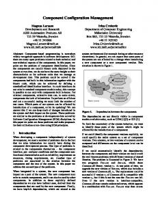
2.3. Requirements for Automated CM Facilities As indicated by the scenario above, there are different kinds of users of CM systems. Each of these users has a specific role and can have a different view of CM and, hence, different requirements for a CM system. These requirements are distinct and generally complementary. Figure 2-1 highlights a set of functionalities that project managers, configuration managers, programmers, testers, QA managers and customers expect of a CM system. This represent what exists with today’s technology. Each box in Figure 2-1 represents a major functionality area. The topology of Figure 2-1 is intended to indicate that the outside boxes (auditing, accounting, controlling, components, structure and construction) are functionality areas that could exist by themselves in any CM system, but when combined with team and process functionality, a holistic (or comprehensive) CM system results. The functionality areas are:
ATR 92
5
CONSTRUCTION
Building Snapshots Optimization Change impact analysis Regeneration
STRUCTURE
TEAM
Workspaces Conflict resolution Families
AUDITING
Versions Configurations Versions of configurations Baselines Project contexts Repository Kinds of components
History Traceability Logging Lifecycle Support Task Management Communication Documentation
Statistics Status Reports PROCESS
ACCOUNTING
System model Interfaces Relationships Selection Consistency
COMPONENTS
Access control Change requests Bug tracking Change propagation Partitioning
CONTROLLING
Figure 2-1: CM Functionality Requirements • Components: identifies, classifies, stores and accesses the components that make up the product. • Structure: represents the architecture of the product. • Construction: supports the construction of the product and its artifacts. • Auditing: keeps an audit trail of the product and its process. • Accounting: gathers statistics about the product and the process. • Controlling: controls how and when changes are made. • Process: supports the management of how the product evolves. • Team: enables a project team to develop and maintain a family of products. The requirements for these areas are now discussed in further detail. For components’ requirements, users need to: record versions of components, their differences, and reasons for those differences; identify a group of components that make up a configuration and versions of those; denote baselines for a product and extensions to those; identify project contexts that represent the collection of components and artifacts related to a particular project. Furthermore, users need repositories or libraries to store and capture 6
ATR 92
components and CM information as well as the different kinds of components such as source and object code, executables, diagrams, documentation and baselines. For structure requirements, users need to: model the structure of the product via a system model that represents the inventory of components for that product; specify interfaces among components, versions, and configurations, thereby making them reusable; identify and maintain relationships between components; and select compatible components to be made into a valid and consistent version of the product. For construction requirements, users need: means to easily construct or build the product; the ability to take a snapshot or freeze the status of the product at any time; mechanisms for optimizing efforts at constructing systems by reducing the need to recompile components and saving space; facilities for doing change impact analysis that predict all ramifications of making a change; and easy regeneration of any phase or part of the product at any point in time. For auditing requirements, users need: a history of all changes; traceability between all related components in the product and their evolution; and a log of all the details of work done. For accounting requirements, users need: a mechanism to record statistics, to examine the status of a product, and to easily generate reports about all aspects of the product and process. For controlling requirements, users need: cautious access to components in the system to avoid any unwarranted changes or change conflicts; on-line support for change request forms and problem reports; means for tracking bugs and how, when, and by whom they are dealt with; propagation of changes, in a controlled manner, across different, but related, versions of the product; and a way of partitioning the product for limiting the effects of changes to it. For process requirements, users need: support for their lifecycle model and their organization’s policies; the ability to identify tasks to be done and how and when they are completed; the ability to communicate information to appropriate people about relevant events; and the facilities for documenting knowledge about the product. For team requirements, users need: individual and group workspaces; the resolution of conflicts when merging changes; and facilities for supporting the creation and maintenance of a family of products. Note that the process box and team box are presented as being the significant areas of functionality. This is because they affect, and are affected by, all the other areas. For a user, an ideal CM system would support all the areas of functionality with team and process support fully integrated. No single, existing system provides all the functionality for the areas.
ATR 92
7
8
ATR 92
3. Configuration Management Concepts The previous chapter explained the breadth of issues addressed by existing systems. The concepts that support some of the functionality areas previously identified with the requirements, are described in this chapter. They are organized as a spectrum to represent an evolution of CM automation as well as relationships between concepts. Each concept is described as it exists in one particular CM system. The functionality areas of interest for the CM system concepts to be discussed are: component, process, a combination of structure and construction features, and team concepts. Figure 3-1 shows the entire spectrum of concepts along with their representative CM systems. A simplified description of each concept, along with its advantages, are highlighted. To begin with, a short note discusses what is meant by "CM system".
3.1. What is a CM System? There is no universally accepted definition for a CM system. That is, there is no unified notion of a CM system. For instance, if a system has version control, is it a CM system? Ideally speaking, a CM system is one that provides all functionality as given in the requirements identified in the previous chapter. But practically speaking, any system that provides some form of version control, configuration identification, system structuring, system modelling, and has the intent of providing CM is considered by the engineering community to be a CM system. It should be noted that existing CM systems provide their own combination of functionality rather than a standard set. While this chapter mentions 15 CM systems to complement the 15 CM concepts in the spectrum, there are at least 40 CM systems that can be acquired for use today. It is intended that the 15 concepts encapsulate the features of all these systems. It is worthwhile to clarify one minor notion for this paper, the notion of a CM system and a CM tool. A CM system can be considered part of an environment, where the CM support is an integral part of the environment and the CM system is sold in that manner as part of a package. For instance, the Rational [38] environment has CM functionality that is an integral part of it. A CM tool can be considered a stand-alone tool. For instance, the Revision Control System(RCS) [39] is a CM tool since it is intended to be installed into an existing environment. But because the distinction is not important to this article, the term CM system will be used to represent both notions.
3.2. Spectrum of Concepts in CM Systems Figure 3-1 presents the spectrum of concepts implemented for CM facilities. It is a snapshot designed to give a quick overview of the status of automated CM support. Before the spectrum is presented, some caveats need to be discussed. It should be noted that the concepts and systems discussed are meant to be representative of what exists, rather than a complete summary or evaluation of what exists. For each concept, one CM system is
ATR 92
9
used to discuss that concept. (Note that some of the CM systems actually provide many of the concepts shown in the spectrum.) Concepts are taken directly from specific CM systems since there is no common terminology when dealing with automated CM functionality — each CM system has its own concepts and semantics. The description of concepts is simplified in order to focus on a certain aspect. As a result, it is realized that this may not highlight the full capabilities of concepts (nor of their systems). But, for the sake of presenting a spectrum and in order to focus in on a basic set of CM concepts, simplification is required. Overviews of the CM capabilities of each CM system referenced in this paper and a more comprehensive listing of the full CM capabilities of each system. can be found in [20].
Legend:
Concept
Direction of evolutiion
Example system
Context Context management management Lifecycle Lifecycle model model CCC*
Transaction NSE*
PowerFrame* Distributed component
Transparent view SMS*
Sherpa DMS* Change Change request request LIFESPAN* LIFESPAN*
Workspace shape* Object pool
System modelling
Repository Repository RCS* RCS*
DSEE*
Jasmine* Attribution Adele*
Contract Contract
Change set ISTAR* ISTAR*
Consistency maintenance
Subsystem ADC* ADC*
Rational*
CMA*
* This system exemplifies the concept shown in the node
Figure 3-1: Spectrum of Configuration Management Concepts
The concepts are organized into functionality areas that represent the requirements they support. The requirements were described in the previous chapter. The areas are: component, structure and construction, team and process. Figure 3-2 shows which concepts are discussed in relation to which functionality area and the concepts are described in detail below. 10
ATR 92
Component
Repository Distributed component
Team Workspace Transparent view Transaction
Structure and Construction Change set System modelling Subsystem Object pool Attribution Consistency maintenance
Process Context management Contract Change request Lifecycle model
Figure 3-2: Requirement Areas and Their Concepts
3.2.1. Component Concepts Component concepts deal with identifying and accessing components of a software product. Described below are the repository and distributed component. These address the requirements for versions, configuration, repository and different kinds of components.
3.2.1.1. Repository The notion of a repository is fundamental to a CM system. The Revision Control System (RCS) [39] provides the notion of a repository for ASCII files. In effect, the repository is a centralized library of files and provides version control for the files in the repository. Any file, while in the repository, is considered to be under a form of CM. The files in the repository are immutable — they cannot be changed. Making a change means creating a new version of a file. All the CM information about files and the content of the files are kept in the repository. Hence, any CM controls pertain to files in the repository. To work on a file, users check out a particular version of it into their working directory, perform any work on it, and, at the their discretion, check it back into the repository. This creates a new version of that file. So that users cannot simultaneously check out the same file and change it, the file checked out is automatically locked (from the repository’s perspective) until checked back in. A version number is automatically associated with a new version; consequently, users can check out any file with a particular version number at any time although the default is the most recent version. Changes to the most recent version result in a new, sequential version whereas changes to older versions result in a variant version. Together, the version numbering scheme and usage pattern result in a version history tree for the file, indicating predecessor/successor versions. The repository stores file history information that includes the different versions of the files, the reason for a change, who replaced that version of the ATR 92
11
file and when. Note that the complete code for the different versions is not stored. Rather, only the actual difference between each version is stored; this is known as the delta. This assists in space savings and access time to the most recent version of a file. Files can be tagged with a state and checked out based on that state’s value. They can also be checked out based on a revision number, date and author. The repository is generally associated with the directory in which the files exist. In sum, a repository captures CM information and stores versions of files as immutable objects.
3.2.1.2. Distributed Component The Sherpa Design Management System (DMS) [22] provides a repository for files distributed on different hardware platforms. The repository is logically centralized, but the data from the repository can be physically distributed. Sherpa DMS is aware of the distribution and carries out its CM taking that into account, for example, by providing some fault tolerance facilities along with the necessary translations of file formats. So, to the users, the distribution is transparent — users carry out their work on the repository as though all the files were located on their own workstations. A team of users geographically dispersed can be working on the same configuration of files. Multiple copies of files can exist on different workstations. Sherpa DMS is aware of the location of the most recent version of a file. Any changes to files in the repository can result in the local copy on the distributed workstations being updated since the system knows where all the local copies are. Updates can occur interactively or be done in batch mode. In effect, distributed users have access to a centralized repository, and to them the CM facilities seem to span the network of heterogeneous workstations.
3.2.2. Structure and Construction Concepts Concepts that deal with: selecting components of a structure; capturing changes to a component and its structure; describing the structure of a product; accessing parts of that structure; constructing the product; and, characterizing and keeping the components of a structure consistent are the change set, system modelling, subsystem, object pool, attribution and consistency maintenance. These are described below. They address the requirements for: building, optimizing derived object space and reducing compilation time, reducing the scope of change, recording information to allow regeneration of components and minimizing the need to regenerate, creating system models, defining interfaces to allow reuse of code, defining relationships between components, selecting the right version of components and checking and ensuring consistency between related components.
3.2.2.1. Change Set Aide-De-Camp (ADC) [1] abstracts a fundamental notion captured in a repository— differences between versions of components—into a difference relationship and makes it accessible to the user. The difference relationship, along with the files to which they apply and other details about changes, make up the change set. ADC captures change to a configuration in a change set and that change set can be used to construct a customized version of a configuration. This change set has a name which means it can be used in operations. The user specifies a formula to create a particular instance of a configuration. The formula
12
ATR 92
designates a baseline to which selected change sets are applied. A change set can be treated as dependent (meaning a version history is followed), or independently of (meaning selective parts of the history are applied), previous change sets. Thus, the user either works from the most recent version or works with a customized version of a configuration. The change set captures all changes to all files in the configuration along with the reason for changes and details of who made the changes and when. The user determines the scope of the change and ADC automatically records all the details of the changes. For instance, the user wants to make major changes to a configuration because of one bug. The user designates a change set and makes changes to the files. In the change set is captured the reason (the bug) for making changes to all files in the configuration; all the actual code changes (which will be different for each file in the configuration); all related file changes; and, details of who made the changes and when. Much of this information is seen when the user browses each file or change set. In sum, the change set represents a logical change to a product and a means of creating any version of a configuration that is not necessarily dependent on the latest version of that configuration.
3.2.2.2. System Modelling System modelling describes a software product—its structure, its components and how to build it. The Jasmine [30] system model is a textual description that the user can alter and that tools can access to carry out their tasks. Jasmine system modelling is described by sets and functions that represent four kinds of information: (1) relations between product components, (2) version binding information, (3) construction rules, and (4) verification rules. The relations describe: the modular decomposition of a product such as the hierarchy of subcomponents, the dependency between components such as the build order of modules, and the grouping of components based on related properties such as grouping all source or object modules. A description of a product via these relations is called a template and captures its structure. Using functional operators and the relations, the user can define more complex relations from the simpler ones. This enables the Jasmine tools to answer userdefined queries such as which components are affected by changing a particular component. System modelling includes the notion of a family to capture the history of the product. A family describes the succession of versions of the components. Various user-specified versions of the product make up a family. Associated with each version are attributes such as creation date and author. Queries, version selection, and rules are based upon the attributes. Construction rules record how existing components were generated and how future components should be constructed, such as recording the compiler, its version and the compiling options needed. Verification rules specify and record the structural and organizational constraints on the product, such as the sources and binary modules must agree (meaning all the binary modules were compiled from those source modules). For selecting a version of a component, a selection expression using families is evaluated against a context that represents a search path for the modules. The resultant modules selected are bound to the template into a data object known as an image. Tools such as brow-
ATR 92
13
sers, module retrievers, debuggers, and inter-module analyzers can reference and manipulate the system models. In effect, system modelling is an abstraction of a product from an instance of it, and by fully describing the product, it assists tools in maintaining the integrity of the product.
3.2.2.3. Subsystem The Rational [38] environment provides for partitioning a large Ada product into parts, allowing for confining the scope of the effects of changes. The parts are called subsystems. Subsystems have interface specifications as well as implementation bodies, and represent configuration items; therefore, they can be treated as wholes and accessed via their names. Components within a subsystem are not visible to components in other subsystems unless they are designated, via the interface specification, to be exported. The Rational environment checks at runtime that the implementation bodies exactly match the interface specification. As a result, work can progress on the implementation bodies independently of the interface specification, which can be changed when the user desires. Recompilations will happen only to components within that subsystem until the interface is changed; at that time, any parts of the product using that interface will need to be recompiled. Changes to an interface specification could possibly require the whole product to be recompiled. Subsystems have version control on their components, and subsystems themselves can be of a particular version. Users can mix-and-match versions of subsystems to make up a particular version of the product. In summary, subsystems represent a way for users to limit the effect of their changes and recompilation, and for the environment to check the validity of combining parts of a product.
3.2.2.4. Object Pool Using its notions for system modelling, the Domain Engineering Environment (DSEE) [23] has all the necessary information to recognize what is required to generate a particular version of a derived object. Derived objects are placed in an object pool to be shared among users. DSEE enables the sharing once the user has indicated the desired derivation properties of the objects. The derived object pool contains a collection of binaries and other objects produced by translation tools. Each derived object has associated with it all information pertaining to its system modelling including versions of sources and translator tools used along with translator options, user comments about the derivation, date, time, person involved and location of the derivation. This information is known as a bound configuration thread (BCT). When DSEE performs a system build, it computes the desired BCT for each component in the system model. DSEE looks into the pool to see if a derived object matching the desired one exists. If it does, it is used; if not, it is built. Thus, whenever a user needs a particular derived object (or a compatible one), DSEE can reuse one from the pool, thereby obviating the need for generating the object. The user need not know that that derived object exists; DSEE does all the checking. Once objects in the pool become defunct (based on a period of non-use), DSEE can delete them, thereby freeing up space. This saves on the amount of compilation time and space required, and reuses work already done. DSEE also provides different kinds of object pools, such as for objects derived from source files that are still checked-out of the repository to a particular user. In effect, the CM system optimizes the need for regenerating components and maximizes sharing of derived objects. 14
ATR 92
3.2.2.5. Attribution The Adele [3] system generalizes upon the repository and system modelling by using an entity relationship database with data modelling capabilities. A product is described in terms of a data model, and Adele performs its operations based on that model. Components of a product are represented as database objects with attributes and relationships. Attributes are associated with each object and characterize that object. An attribute has a name and a value. An example is the attribute name "delta" which represents whether the object exists in ASCII form and so can be compressed; it can have a value of "true" or "false". Two kinds of attributes are distinguished: predefined and user-defined. The former are managed by Adele, and the latter are declared and managed by the user. One predefined, special kind of attribute is "type". This "type" attribute is mandatory and immutable for each object. It represents the main CM entities in Adele (such as the composed object, the document, the revision and the element). Relationships define dependencies between objects; for example, object B is derived from object A. The user can describe a configuration in terms of characteristics of objects, rather than in terms of a list of specific versions of objects. Adele instantiates and builds a configuration using selection rules and constraints centered on the attributes and relationships. The user can define any structure (rather than just a hierarchical structure) to a product in terms of desired characteristics. Thus, the user can describe a product at a higher level of abstraction via its characteristics rather than in terms of a composition of lengthy file lists.
3.2.2.6. Consistency Maintenance The Configuration Management Assistant (CMA) [19] provides configuration construction and validation based on an abstract description of the product as well as on information about the successful or unsuccessful usage of components forming the configuration. The data modelling facilities include predefined attributes and relationships with which the user describes configurations. Based on the semantics of those attributes and relationships, CMA can determine whether a configuration (which is a set of instances of components) is usable. To be usable, a configuration must be complete, unambiguous, consistent and lack version skews. This means a configuration must consist of all instances of components required and must not contain multiple instances of a component. The classes of attributes represent user-defined characteristics such as constraints, types, and versions. Classes of relationships represent kinds of dependencies, such as logical, compatible, component, instance, and inheritable dependencies. Every time a new configuration is constructed, CMA utilizes the information that accumulated in the database via the previous use of the components forming the configuration. In this way, CMA predicts whether the configuration is usable. This new configuration is added to the database for future analyses of usability. Thus, the user can rely on the system to identify any inconsistencies and to preserve consistencies in creating and re-using configurations.
ATR 92
15
3.2.3. Team Concepts Concepts that deal with the isolation, co-ordination and synchronization of software engineering teams working on a product are workspace, transparent view and transaction. These address team requirements such as work areas for isolating work, synchronizing concurrent work, limiting the scope of a change, merging conflicts of changes and handling families of products.
3.2.3.1. Workspace The notion of a workspace in "shape" [46] is designed to prevent users from interfering with one another’s work. It provides the notion that work can proceed on mutable objects that are under CM. The workspace is achieved via a version status model. This means that an attribute "state" is associated with a version of a component. Depending on that state (such as state "busy" or "frozen"), the component is considered to be in either a private workspace or in the public repository. A "busy" component is mutable and not usable by others, whereas a "frozen" one is immutable and available for public use. Components are promoted to the public repository making them available for public use after being approved by appropriate people. In effect, the workspace provides isolation of work and suggests a distinction between a global, long-term repository for immutable objects and a private, shorter-term repository for mutable objects.
3.2.3.2. Transparent View The Software Management System (SMS) [47] enhances the notion of a workspace by making it an explicit object and providing a transparent view of the repository in that workspace. This means that only the versions of the files in which the user is interested will be seen in the workspace; all other versions are hidden from view (although they physically exist). For example, any changes made to the latest public version need not be seen in the workspace. The user is isolated from public changes and the workspace gives the appearance of a specialized repository for the user. Version control with workspace-relative version numbering is provided in the workspace. New versions are private and not publicly visible until released from the workspace. A configuration is checked out from the public repository to the workspace, and users are assigned access to that workspace. Components in the workspace effectively belong to that workspace rather than to a user. Only the user registered with that workspace can change the configuration and only components in that workspace can be accessed. In sum, the transparent view provides a viewing mechanism with protection against unauthorized access to a configuration.
3.2.3.3. Transaction The transaction notion of the Network Software Environment (NSE) [34] represents a coordinated unit of work. It reflects the structure of a product and supports the isolation of work, interactions between users, and the merging of changes. A transaction involves an environment and a set of commands. The environment provides notions similar to a workspace and a transparent view. It shows the directory structure used to store source and derived objects. Commands such as "acquire", "reconcile", "resynch" and "resolve" provide the interactions across environments. They represent a protocol used to coordinate and syn-
16
ATR 92
chronize the actions between users and represent the communication of the actual changes. Users work independently in their environments, changing the same or different configurations. The user can update the repository with a new version of the configuration. NSE assists in merging the changes into the repository. But it checks that what exists currently in the repository (which could have been placed there by some other user) does not conflict with the new changes coming. If there is a conflict, NSE notifies the user about the merging problems and provides assistance in eliminating the conflicts. Users can request that any changes made to the repository be incorporated into their own workspaces. In sum, the transaction synchronizes and co-ordinates teams changing the same or different parts of the product.
3.2.4. Process Concepts Concepts that deal with process related functionality are context management, contract, change request and lifecycle model. They address requirements for lifecycle support, task management, communication and automatically recording information.
3.2.4.1. Context Management PowerFrame [37] is a system designed for the computer-aided engineering/design field and essentially shields its users from low-level details of the file system and configuration management. Users see only their domain-specific world of circuit design, and PowerFrame manages the work context for the user. Project data is represented graphically rather than as being hidden in directories. PowerFrame provides workflow management to guide team members through their work processes. For example, a tool-run may involve creation of a circuit, validating it, then simulating it for determining its performance characteristics. During these actions, PowerFrame automatically derives the current context related to the tool run such as the data sets, command files and options used for invoking tools. The next time, the user needs only to select the circuit design and the tool function to return to the work. The user sees the appropriate tools for a particular task; certain forms of data presentation such as a logic-schema or a layout design; data that are pertinent to a particular task; and the forms of commands that are pertinent to that domain. The user can perform actions on different granularities, such as a single data item or a configuration, of the context’s data. The user does not have to worry about such tasks as version control or relationships between files, since the system, knowing about the derived data from various versions of circuits, handles those tasks behind the scene. In effect, the CM system captures, in a domainspecific way, the working context for the user, thereby eliminating the need for users to remember how they got to a particular working status and what all the data items and their relationships are in that context.
3.2.4.2. Contract The ISTAR [29] environment provides for modelling some parts of a software development process in terms of a formal agreement—a contract— to perform tasks with specified input and deliverables. Artifacts of the contract are recorded and are configuration items. A contract models information flow, the start and completion of tasks, the passing of results from the tasks and components of the product, and are "exchanged". A contract is fulfilled by the
ATR 92
17
"passing" of the deliverables subject to specified acceptance criteria. The deliverables are passed to certain elements of the process model such as to a different phase of the lifecycle or to a person. Movement of these artifacts is subsequently tracked. The work in progress on the contract can be monitored, since various artifacts (such as communications) are recorded. In effect, the contract represents a formal plan for, and a record of, a unit of work on a configuration item.
3.2.4.3. Change Request In LIFESPAN [31], a change request represents a documented request for a change and an associated process model for change. LIFESPAN models the change request via a series of "forms" and the process of change via a series of states, tasks and roles. A customer may submit an on-line Software Performance Report (SPR) which identifies a fault or a request for an enhancement for versions of components. This allows the report to be investigated by circulating it to the original designers and implementors who can diagnose the problem. In response to the SPR and change impact analysis, an on-line Design Change (DC) is proposed. This details exactly what components are to be changed and how. LIFESPAN analyses who would be affected by the change. Those people are then automatically chosen to be the Change Control Board. They are notified by electronic mail about the DC and must vote within a certain time frame on whether to approve the change. Once the DC is agreed to, a new development version of the code to be changed is made, the DC’s state becomes "active" and the code to be changed is locked. Upon completion of the changes, the new version is frozen and submitted for checking and approval to a person with QA privilege. Upon approval, the code changes acquire an "approved" status, the status of the DC becomes "approved" and affected users are notified by electronic mail that the new version is available. The users are notified via a Software Status Report (SSR) which closes off the original SPR. Thus, the SPR, DC and SSR not only provide a means for users and maintainers to communicate, but they also represent a history of changes related to a particular change request; status reports for changes in progress; audit trails of changes completed; a supporting mechanism for change impact analysis and ensuring that the appropriate people carry out their tasks at the right time. In effect, change requests assist in driving the process of change.
3.2.4.4. Lifecycle Model Change and Configuration Control (CCC) [16] provides notions for supporting a particular lifecycle model in the sense of supporting the transition between phases and people in a lifecycle, and the tasks and data management to be performed during those phases. CCC does this by separating out the phases into developing, testing, approving and releasing of a product. This separation allows different kinds of users such as programmers and testers to independently perform their work on the same code simultaneously. The separation of, and transition between, phases and independent work are achieved by passing the code through to separate configurations that represent each phase. That is, the product is developed as a sequence of configurations and evolves as such. The product exists as four configurations: development, test, approved and production. Code development occurs in the development configuration, passes to the test configuration for review, then to the approved configuration pending release, and to the production configuration for use by the customer. In order to be 18
ATR 92
passed onto the next phase, a protocol of interactions required by various users (such as the Project Manager and Test Manager) must authorize the transition. In effect, a lifecycle model is achieved via transitions between configurations.
3.3. Summary and Analysis of the Spectrum Figure 3-1 represents a spectrum of CM concepts provided by various CM systems. The concepts and their purposes are a repository for capturing the history of immutable files; the distributed component for distribution of data under CM; the contract that represents a plan for a unit of work; a change set that captures changes to a configuration and allows selection of configurations independent of the latest version; the lifecycle model that enforces an organization’s process of software evolution; system modelling for fully describing and recording the structure and building of a product; the object pool for enabling the re-use of derived objects, thereby optimizing product building; attribution that allows the selection of a configuration based on characteristics other than a long list of files; consistency maintenance for automated checking and prediction of inconsistencies between components of a configuration; the workspace for isolating private changes to mutable configurations; a transparent view for viewing configurations and protecting against un-authorized access to mutable configurations; and a transaction for co-ordinating changes to configurations by a team. These concepts represent advances in CM system functionality. The topology of the spectrum is intended to show an evolution of concepts. For instance, from left to right of Figure 3-1, generally speaking, there have been advances in modelling various processes, capturing components, describing components of a product, optimizing product construction, characterizing component dependencies and co-ordinating team work. The "arms" of the spectrum indicate related progress. For example, the change request and lifecycle model as described in this paper are related: the lifecycle model subsumes a certain change request model and the change request operates with a repository. There are notions that the spectrum cannot show (such as the recognition of roles) which is further discussed in [20], as are difficulties in extracting concepts from CM systems due to overloading of concepts. There really is no common vocabulary when talking about CM concepts. The distinction between concepts and their implementation is not always clear. For instance, implementations of workspaces vary across CM systems and hence provide different functionality to the user. Thus, should the concept of the workspace be the lowest common denominator of all implementations, or the opposite? Are workspace, transparent view and transaction really one notion since a transaction subsumes notions of a workspace and transparent view? Or are they really three concepts, as shown in the spectrum? The spectrum of concepts provides a starting point for developing, or at least extracting, a set of fundamental CM services from existing CM systems.
ATR 92
19
20
ATR 92
4. CM Systems The previous section has focused on illustrating the spectrum of CM concepts found in different CM systems. In this section we focus on CM systems. No single CM system offers the full spectrum of CM concepts. Minimally, commercial CM systems typically offer a repository for retaining the version history. CM systems that target project CM, i.e., the formal control function of change request management, complement the repository with a change order tracking facility. Typically, the repository and change orders are loosely coupled via naming conventions. CM systems geared toward developer CM, i.e., supporting developers who perform the actual changes to a system, complement the repository with a system build facility. When examining a number of commercial CM systems we have observed certain patterns of CM concepts in support of the repository. These patterns can be described as four major CM repository paradigms: the checkout/checkin paradigm, the composition paradigm, the long transaction paradigm, and the change set paradigm. Normally, a particular CM system primarily implements one paradigm, complementing it with the checkout/checkin paradigm to provide coordination where appropriate. The four paradigms characterize the capabilities of individual CM systems. Each of the paradigms supports certain aspects of a CM process. One paradigm by itself does not generally support all the needs of a user. Any incompleteness must be addressed via extensions or usage conventions. The section proceeds by summarizing each of the paradigms and discussing their appropriateness in the software process. Then, a number of CM systems are characterized in terms of the paradigms. For a full discussion of the four paradigms refer to [33].
4.1. Four CM Paradigms Each of the paradigms focuses on a particular aspect of CM. The first paradigm is the wellknown checkout/checkin paradigm. It provides versioning of individual components and concurrency control on components through locking as well as through branching and merging. The other three paradigms reflect advances in CM functionality over this basic paradigm. The composition paradigm focuses on the creation of configurations in a two-step process - the description of the composition structure of a system in terms of its components, and the selection of an appropriate version for each of the components. In this paradigm, the link to system build capabilities is most prevalent. The long transaction paradigm focuses on the evolution of a system as a series of configuration versions and the coordination of development teams changing a system simultaneously. This paradigm emphasizes support for developers actively making modifications by managing their workspaces. The change set paradigm focuses on the evolution of a system in terms of logical changes. This change-oriented view of CM emphasizes support for managing the propagation of logical changes throughout a system family. Change sets represent the actual modifications making up a logical change. They provide the link to managing the change process through change requests.
ATR 92
21
4.1.1. The Checkout/Checkin Paradigm The checkout/checkin paradigm embodies repository support for versioning of components, including branching and merging, and concurrency control through locking of version sequences. Figure 4-1 shows how a CM system supporting the checkout/checkin paradigm presents itself to a user. The user works with a repository and with the file system. Files are versioned and stored in the repository. Creation of new versions is controlled by the repository. Files are, however, not directly accessible in the repository. Users have to retrieve, or check out, a version of a file into the file system in order to access it. Files are retrieved for reading or for modification. In the latter case, a locking mechanism guarantees mutually exclusive modification within a version branch. Modified files can be stored back into the repository, or checked in, resulting in a new version of the file.
Source repository
A
File system work area
B
checkout
A
A.obj
C
C.obj
checkin update transfer
C
build
build script
Figure 4-1: Operational Model for Checkout/Checkin
The file system is the actual work area for the user and tools. While a retrieved file resides in the file system, it is outside the control of the CM system. Access control and write locking mechanisms of the file system are relied upon to guarantee exclusive access for modifications. A CM system may additionally support access control on the repository. An access control list may determine whether a particular person is permitted to check out a file for modification. The user operates tools, including the system build tool, in the usual manner. The tools are not aware of versioning of files and selection of the desired version. Directory hierarchies can be used to structure the files which are the components that make up a system. Build tools may simply be command scripts or tools that interpret a description of
22
ATR 92
the files in the file system that make up a system. These descriptions or command scripts can be stored and versioned in the repository. They represent a description of the configuration of a system alone, regardless of versioning. The checkout/checkin paradigm provides the following conceptual primitives for versioning of files: evolution of a sequential version history (referred to as revisions); creation of version branches, that is, version sequences that have as their starting point a particular version in an existing branch, but evolve independently; and merging of two versions from different branches into a new version in one of the branches. The result is a version history for files that has a graph structure. This structure is referred to as a version graph. A version branch is used for several purposes: • To represent an independent path of development. For example, the maintenance of a component as part of a field release vs. its further development. • To represent different variants of the component. Variants may reflect different time- or space-efficient implementations, ports to different platforms, interfacing with different window systems, etc. • To represent experimental development, which may be abandoned or folded into the primary development at a later stage. • To accommodate for the fact that two developers were required to make changes concurrently to a component, thus making serial update of the component too restrictive. In this case the branch exists only temporarily and is merged as soon as both modifications are completed. These interpretations of branches are based on usage conventions that users place on the CM system rather than on usage patterns that the CM system directly supports. The checkout/checkin paradigm supports merging of branches. Merging consists of two elements: recording of the merge history in the version graph, and the merging of the actual component content. Different implementations of the checkout/checkin paradigm offer varying semantics for merge. Some merge semantics support propagation as well as merging. Some merge semantics restrict merging to the ancestor version branch. Such restrictions impact which of the above branch usages are well supported. For a full discussion of the range of merge semantics see [33].
4.1.2. The Composition Paradigm The composition paradigm focuses on improving support for creating configurations, for managing their history, and for using them as working contexts under the auspices of a CM system. A configuration in this paradigm consists of a system model and version selection rules. A system model lists all the components that make up a system. Version selection rules indicate which version is to be chosen for each component to make up a configuration. The selection rules are applied to a system model, selecting a component version, or binding a component to a version. The mode of operation in this paradigm is that developers define the system in terms of its components and, in a separate step, select an appropriate version for each component. This mode of operation for dealing with versions is illustrated in Figure 4-2. In this Figure components are shown as boxes with square corners, while configurations are shown as boxes with rounded corners. ATR 92
23
A
B
C
1.0
1.0
1.0
1.1
1.1
1.1
1.2
System
1.2
A
B
C
Figure 4-2: Component Version Selection
There is a two-step process of composition and selection. One step is the aggregation of components into a composite and the other step is the selection of an appropriate version for each of the composite elements. The selection step can occur at any level of the system composition, thus allowing a CM system to provide flexible support for management of system variants, that is, system families at different levels of granularity. The composition paradigm accommodates management of a system family. Typically, variants are represented by branches and are identified by branch labels. Selection of alternative members of a family becomes a matter of indicating alternative variant choices in the selection rule. This is done for the complete system configuration or for sub-configurations (subsystems). The latter is accomplished by limiting the selection option to a subset of the components—either by listing them individually or by referring to an aggregate in the system structure. Thus, developers can indicate selection of alternative family members at any level of the system structure in a natural way. In the composition paradigm, configurations have version history. They may be versioned by versioning the system model and the selection rules, and by giving bound configurations version names. Developers can choose a particular configuration to be their working context. Working context means that as developers are accessing different components of a system, whether directly or through tools, by default the version indicated by the configuration description is used. The version may be selected when the component is retrieved from the repository or when it is accessed transparently. (The notion of transparent repository access is discussed in the long transaction paradigm.) A bound configuration provides a more stable working context than does a partially bound configuration. A partially bound configuration may be explicitly applied by the developer to retrieve components, thus effectively creating a bound configuration in the work area. This configuration will not change until the developer updates the work area by applying the partially bound configuration again. In other words, the developer decides when to upgrade the work area through an explicit command. 24
ATR 92
Alternatively, a partially bound configuration may be rebound every time a build is performed. In this situation, developers may instead choose fully bound configurations in order for the work area not to change constantly. In other words, developers control the content of their work area by choosing different selection rules (possibly defining new ones) or combinations of selection rules and system models to be their current working context. The use of a configuration as a working context has important implications on the management of derived files. The build tool produces derived components from source component versions that the CM system is aware of. For a bound configuration, the component versions are constant. Thus, the build tool has to be concerned only with changes to components that are accessible for modification. For partially bound configurations, the build tool and the CM system must interact to enable the build tool to guarantee consistent update of derived components. Through cooperation with the build tool, the CM system can become responsible for storing derived components in the repository. CM systems, system build tools, and language systems must cooperate in order to avoid putting the responsibility of maintaining redundant system model information on the user. Unfortunately, there is a wide range of CM systems, system build tools, and language systems with varying approaches to system model support, making their integration into a development environment a nightmare.
4.1.3. The Long Transaction Paradigm The long transaction paradigm supports the evolution of whole software systems as a series of atomic changes and provides team support through coordinating of concurrent change. Developers operate primarily with versioned configurations. Developers first select the version of the system configuration, then focus on the system structure. The version of the components has implicitly been determined by the configuration. It is contrary to that of the composition paradigm, where the developer is first concerned with the system structure, and then focuses on the selection of component versions. A change is performed in a transaction. A particular configuration is chosen as the starting point for changes. The modifications are not visible outside the transaction until the transaction is committed. Multiple transactions are coordinated through concurrency control schemes in order to guarantee no loss of changes. The result of a transaction commit is a new configuration version. The result of a series of sequential changes is a sequence of configuration versions, referred to as a development path. Configuration versions can branch from an existing development path, resulting in a new, independent development path. It is called independent because both paths can evolve independently. This interpretation of the version graph of a configuration is illustrated in Figure 4-3. The long transaction paradigm differs from a traditional database transaction. The database transaction performs an update operation on the database, while a long transaction creates a new version of modified data elements. The long transaction also differs in that it is persistent. This means that the long transaction may have a duration of hours, days, or months, and it must exist beyond the duration of a developer’s login session as well as potentially
ATR 92
25
Development path
| | |
Transaction
Figure 4-3: Version History of a Configuration
beyond the uptime of a developer’s workstation. Finally, a long transaction may represent the work of a group of developers with coordination among them through nested transactions, while a database transaction represents one activity and nesting is primarily used to decompose the update into finer grain operations. A long transaction has two elements: a workspace, and a concurrency control scheme. A workspace represents the working context and provides local memory, that is, data storage visible only within the scope of the workspace. As such, the workspace replaces the use of the file system as the work area, allowing the CM system not only to manage the repository, but also to support developers while they change the system in their work areas. By mapping the workspace into the file system, transparent access to the repository is achieved, eliminating the need for users to explicitly transfer components between the repository and the file system as work area. A concurrency control scheme is a policy for coordinating concurrent change. Typical examples of such a policy for database transactions are various protocols for serialization of transactions. A number of different policies can be found in actual CM systems, each with a different degree of concurrency and cooperation among developers. While operating in a workspace, the developer is isolated from changes in other workspaces and from changes committed by others to the repository. Propagation of changes both out of and into the workspace are explicit operations and under the control of the developer. This is due to the fact that changes are made relative to the originating configuration and this configuration is an immutable bound configuration. The workspace is not up to date if a configuration version newer than the originating version exists. The user of a workspace can find out about this fact and ask for the workspace to be updated, resulting in a new originating configuration. Depending on the concurrency control scheme deployed, conflicts between changes existing in the workspace and those in the updated originating configuration have to be resolved (this is further discussed under the concurrency control section). Workspaces can be nested. Instead of originating from the repository, a workspace can orig-
26
ATR 92
inate from a preserved configuration of another workspace. The result is a hierarchy of workspaces corresponding to a hierarchy of nested transactions. Each workspace represents a separate scope of visibility for changes. The bottom workspaces represent the work area of individual developers. The next level workspace represents the work area of a development team, while the third level workspace represents a testing area. Individual developers commit their changes to the team workspace, making them available for other developers to include in their workspaces. From the team workspace, configurations representing consolidated changes of team members are made available to the testing team by committing those configurations to the testing workspace. Finally, configurations passing a test suite may be released into the repository. Support for concurrent development falls into three categories: concurrency within one workspace; concurrency between workspaces requiring coordination; and concurrent, independent development. The first two categories address concurrent changes to one system configuration, while the third category assumes that a system evolves in independent development paths. These changes do not require coordination during their creation. They can later be serialized through propagation and merging, if desired. Concurrency that requires coordination between workspaces occurs when different developers work in separate stable workspaces and the collection of their changes evolves a system. Schemes for controlling concurrency in this situation fall into two categories: conservative and optimistic schemes. Conservative schemes require a priori locking across workspaces. The optimistic scheme allows modifications to occur concurrently, and conflicts are detected at the time it is committed. A range of different concurrency control schemes are found in different CM systems. Typically, a CM system supports a single concurrency control scheme thereby restricting team interactions.
4.1.4. The Change Set Paradigm The change set paradigm focuses on supporting management of logical changes to system configurations. The change set concept, introduced by this paradigm, represents the set of modifications to different components making up a logical change. It is the record of a logical change that persists after the activity creating the change has completed. Users of a CM system supporting this paradigm can directly operate with change sets. The change set paradigm supports change-oriented configuration management in a natural way. It provides a link to change requests, which are a management tool for controlling the software process through change authorization and status tracking. While change requests contain information about a change, change sets represent the actual modifications. Developers can track logical changes and determine whether these changes are part of a particular configuration. This view of configuration management, referred to as change-oriented configuration management due to its focus on logical changes, differs from the version-oriented view of configuration management present in the other three CM paradigms, which focuses on versioning of components and configurations. Change sets allow developers to view configurations in terms of collections of logical changes. Figure 4-4 shows how a version of a configuration is made up of a particular base ATR 92
27
version plus certain changes. Logical changes are propagated by adding change sets to appropriate configurations. New configurations are created by adding a combination of change sets to a baseline configuration. There are, however, constraints on which change set combinations are consistent. Some change sets are dependent on the presence of other change sets. Some change sets are in conflict with other change sets. Changes are propagated to other configurations by including the respective change set.
SYSTEM
A
Fix 1
+
B
C
Change Set 1.1
Feature 4
+
Change Set 2.4
D
Figure 4-4: Change sets in Use
Different integration strategies can be pursued for collections of concurrent logical changes by combining them in particular order. Appropriate queries can determine the degree to which logical changes have spread throughout a collection of system configurations being maintained. Although change sets relate to transactions, they do not provide concurrency control. Thus, CM systems complement the change set paradigm with the checkout/checkin paradigm. Merge mechanisms necessary to support optimistic concurrency control are also applicable to determining and resolving change set conflicts. Current CM systems either provide limited support for logical changes through naming of component and configuration versions, or offer support for the change set concept, but place little restriction on consistent combination of change sets into configurations. However, many practical development scenarios have change propagation patterns that result in few change conflicts.
4.2. Characterization of CM Systems In our endeavor to assess the state of commercial CM support we have found a proliferation of CM concepts. They are found in stand-alone CM tools, in environment frameworks, and embedded in CASE tools. The following tables characterize some of the CM systems we have examined. Figure 4-5 characterizes several stand-alone CM tools based on the four paradigms. The systems shown in the table are UNIX SCCS and RCS, Software Maintenance & Development Systems Aide-De-Camp, Softool CCC, and CaseWare Amplify Control. These systems provide a repository and complement it with either a system build facility or a change tracking facility. The base system offers the checkout/checkin paradigm, in some cases com28
ATR 92
CM model
System
Comments
Unix SCCS
checkout/checkin (co/ci)
Unix RCS
co/ci
configurations as labels
SMDS Aide-De-Camp
change set + co/ci
turnkey systems
Softool CCC
transaction + co/ci
labels for logical changes turnkey systems
CaseWare Amplify
composition + co/ci
turnkey systems
Figure 4-5: CM Paradigms in Stand-alone CM Tools
plementing it with one of the other paradigms to a certain degree. Typically users of the CM system develop conventions of usage that are appropriate for their needs. Those conventions are in many cases encoded in a layer of command scripts on top of the base system resulting in a turnkey version of the system. The conventions often compensate for the lack of a certain paradigm in the base system and lack of CM process support. Figure 4-6 shows two environment frameworks, Apollo DSEE and Sun NSE, in terms of the four paradigms. These frameworks are interesting examples for several reasons. Their view of CM support is that it is a key element of an environment rather than a tool that is to be invoked at appropriate times. In order to make CM support pervasive access to the repository is provided transparently. The versioned components are mapped into the file system and are accessible to tools without the tools being aware of the CM service.
System
CM model
Comments
Apollo DSEE
composition +co/ci
logical change record in task log
Sun NSE
transaction
multi-level transactions with optimistic concurrency
Figure 4-6: CM Paradigms in Environment Frameworks
Figure 4-7 lists several developer tools with multi-user support, that is, Rational Environment, Procase SmartSystem, and Interactive Development Environments (IDE) Software Through Pictures. The figure illustrates how different tools take different approaches to managing derived objects. The Rational Environment supports partitioned program libraries, versioned together with the source. Procase Smartsystem versions all object code with the source as a single entity. IDE Software Through Pictures does not version the data dictionary, leaving it to the developer to appropriately use it. ATR 92
29
The multi-user support in these developer tools has resulted in a certain amount of CM support being embedded in the tool. When such tools are used in the context of other tools or a CM system, the CM concepts supported by each have to cooperate. These tools have a complex architecture, consist of several components, and use sophisticated data management schemes. Either the sources are maintained in the file system while derived information is kept in a data dictionary, or both sources and derived information is maintained in a tool-specific repository. Versioning of these tool repositories raises a number of technical issues which are hinted at in the next chapter on integration issues.
System Rational Environment
CM model
Comments
transaction + composition
two-level transactions with component locking composition of subsystems
Procase Smartsystem
transaction
one-level transaction on single path locking & optimistic schemes
IDE Software Through Pictures
composition + co/ci
no data dictionary versioning
Figure 4-7: CM Paradigms in Developer Tools
In summary, the following observations can be made about CM support in commercial systems. Many CM systems focus on one conceptual paradigm, in many cases complementing it with the checkout/checkin paradigm. Little commonality of CM functionality exists across CM systems. And there is a lack of identification and standardization of CM tool interfaces. Implementations of CM concepts and paradigms vary from system to system. In particular, a range of restrictions can be found on the branch/merge version history of components. Similarly, a variety of concurrency control schemes can be found in support of coordinating teams and controlling change. In many cases the CM system chooses a single concurrency control scheme, limiting its applicability to different team structures. Since each of the conceptual paradigms emphasizes support for a particular aspect of the software process, no single CM system will satisfy all developer needs. Therefore, either the capabilities of a CM system are extended by users through usage conventions, or the capabilities of several CM systems and other tools may have to be combined to achieve a particular functionality. Usage conventions are often encoded in command scripts, or in a tailoring layer turing a base CM system into a turnkey system. Combining of tool capabilities, such as change request tool and a CM data repository, are typical. CM support is found in CM tools, CASE tools, and environment frameworks. Integrating tools into a software development environment raises integration issues specific to the
30
ATR 92
domain of configuration management. The next section discusses the state of integration of CASE tool and CM in that context.
ATR 92
31
32
ATR 92
5. Integration of CM and CASE Tools The previous chapters outlined the state of CM technology from the standpoint of a spectrum of concepts underlying automated CM, and from the standpoint of the reflection of some of these concepts in commercial CM products. Clearly, no CM product supports all CM concepts; similarly, not all CM concepts are necessary in the support of all possible end-user requirements. That is, different CM tools (and the concepts which underlie these tools) may be required by different organizations or projects, or within projects at different phases of the software development life cycle. This observation, coupled with the observed, continuing industry effort to adopt computer-aided software engineering (CASE) tools, leads us to conclude that integration is key to providing automated CM support in software development environments. In this chapter we define what we mean by integration by way of a three-level model of integration. We illustrate where CM integration fits into this three-level model. We then describe the advantages and disadvantages of current approaches to achieving integration in software development environments. We close with a brief discussion on the relationship between future integration technology and the three levels of integration.
5.1. CM Services in Software Environments: A Question of Integration There is no concensus regarding where CM services should reside in software environment architectures, despite the diversity of approaches that have been explored. For example, CM services have been offered via: • Tools such as RCS, SCCS, CCC. • Operating system extensions at the file-system level such as DSEE and NSE. • Shared data models such as in the CIS specifications [18] and the PCTE PACT [53] environment. A further complication is the emergence of a robust CASE tool industry, wherein many popular CASE tools provide their own tool-specific repository and CM services. As a result, CM functions are increasingly provided by, and distributed across, several CASE tools in an environment. We have found it useful to think of integration in terms of a three-level model. This model, illustrated in Figure 5-1, corresponds to the ANSI/SPARC [48] three-schema approach used to describe database architectures. A useful intuition is that this correspondence is more than accidental. The bottom level of integration, called "mechanism" integration, corresponds to the ANSI/SPARC physical schema level. Mechanism integration addresses the implementation aspects of software integration, including, but not limited to: software interfaces provided by the environment infrastructure, e.g., operating system or environment framework interfaces; ATR 92
33
Process Integration (external view)
Process Adaption
Service Integration (logical view)
Implementation
Mechanism Integration (physical view)
Figure 5-1: Three Levels of Integration
software interfaces provided by individual tools in the environment; and architectural aspects of the tools, such as process structure (e.g., client/server) and data management structure (derivers, data dictionary, database). In the case of CM, mechanism integration can refer to integration with CM systems such as SCCS, RCS, CCC and DSEE; and CM implementation aspects such as transparent repositories and other operating-systems level CM services. The middle level of integration, called "services" integration, corresponds to the ANSI/SPARC logical schema level. Services refers to the high-level functions provided by tools, and integration at this level can be regarded as the specification of how services can be related in a coherent fashion. In the case of CM, these services refer to elements of the spectrum of concepts discussed in chapter 3, e.g., workspaces and transactions, and services integration constitutes a kind of unified model of CM services. The top level of integration, called "process" integration, corresponds to the ANSI/SPARC external schema (also called "end-user") level. Process integration can be regarded as a kind of process specification for how software will be developed; this specification can define a view of the process from many perspectives, spanning individual roles through larger organizational pespectives. In the case of CM, process integration refers to policies and procedures for carrying out CM activities. Integration occurs within each of these levels of integration; thus, mechanisms are inte-
34
ATR 92
grated with mechanisms, services with services, and process elements with process elements. There are also relationships that span the levels. The relationship between the mechanism level and the services level is an implementation relationship: a CM concept in the services layer may be implemented by different tools in the mechanism level, and conversely, a single mechanism may implement more than one CM concept. The relationship between the services level and the process level is a process adaptation relationship: different CM services may be combined, and tuned, to support different process requirements. This three-level model provides a working context for understanding integration. For the moment, however, existing integration technology does not match exactly this somewhat idealized model of integration. For example, many services provided by CASE tools (including CM) embed process constraints that should logically be separate, i.e., reside in the process level. Similarly, tool services are often closely coupled to particular implementation techniques. The level of adaptability required of integrating CM—both in terms of adaptability for projectspecific requirements as well as adaptability to multiple underlying CM implementations—pushes the limits of available environment integration techniques. The following sections describe the current state of integration technology and its limitations. The next chapter discusses how future generation integration technology can address these shortcomings.
5.2. Current State of Integration Technology Current generation integration techniques can be thought of as belonging to one of two integration paradigms: the Integrated Project Support Environment (IPSE) paradigm and the CASE coalition paradigm. These paradigms emerge from two independent technology families that have evolved (more or less) in parallel during the 1980’s. The relationship of these paradigms to each other, and to their hypothesized unification in the form of federated environments, is depicted in Figure 5-2. The IPSE paradigm is the result of research and development in software development environments. The distinguishing characteristic of this technology family is that software environments are conceived of as coherent, designed software systems that support some underlying conceptual and architectural models [21], some of which are shown in Figure 5-2. The conceptual and architectural models underlying the IPSE approach include strong process support for programming-in-the-large/many and tool integration via shared ‘‘hub’’ services, particularly repository services. The coalition paradigm is the result of the development of CASE tool technology in the USA. The distinguishing characteristic of this technology family is that software environments are conceived of in terms of a collection of tools from multiple tool vendors that have been ‘‘hard-wired’’ together, rather than in terms of a unifying conceptual and architectural model. Coalition environments are the result of strategic vendor alliances (e.g., Software through Pictures (StP), FrameMaker, and SabreC). ATR 92
35
CASE Tool Market Technology
Software Environment Technology
Language-Centered Environments
Methods-Based Environments
Current Technology
Tool Kit Environments
Unintegrated Single-User CASE
Structure-Oriented Environments
Unintegrated Multi-User CASE
CASE Coalition
First Generation Integrated Project Support Environment (IPSE)
Current Technology
CASE Federation
Future Generation IPSE
Figure 5-2: Evolution of Integration Technology Streams
In response to the inherent limitations of the IPSE and coalition paradigms, the federated paradigm is just beginning to emerge [55]. Federated promises to combine the strengths of IPSE environments—strong project support and well-defined software process models—with the strengths of coalition environments—strong developer support and access to commercial CASE tools. The federated paradigm is based upon integration of services, rather than integration of tools. The services model separates the implementation of a service from its logical description, thus supporting multiple service implementations, perhaps existing simultaneously, in an environment. The services model also encourages the definition of service domains—collections of related services—that can provide a virtual machine layer for conceptual interfaces such as the unified model of CM. The following sections discuss the strengths and weaknesses of IPSE-style and coalitionstyle integration, and outline the emerging federated-style integration model that promises to merge the IPSE and coalition environment technologies. While the focus of discussion will be the implication of these integration paradigms on CM integration/interoperation, we believe that similar arguments hold for integration of arbitrary software processes, tools, and services.
36
ATR 92
5.2.1. IPSE Integration While the IPSE concept does not dictate a particular architectural model, in practice most exhibit the fundamental architecture characterized by the Stoneman reports [50, 51], which described the requirements and architecture of Ada Programming Support Environments (APSE). Stoneman envisioned an architecture for environments centered around a shared database. This database was expected to provide the essential services for tool integration. Later extrapolations of the Stoneman vision from programming support to project support—i.e., from APSE to IPSE— extended the role of the central environment database to include support for the definition and enforcement of software development processes (for example, through enhanced semantic modelling capabilities and database trigger mechanisms).
5.2.1.1. Advantages of IPSE Integration The Stoneman IPSE architecture is conceptually simple, with a well-defined interface for access to the kernel operating system, database services, and minimal tool set providing the focal point for much subsequent work. The central database approach envisioned easy tool integration by simply increasing the data structuring from uninterpreted Unix byte-streams through the addition of additional semantic structures (e.g., parse trees, symbol tables, etc.) as could be found in programming environments such as InterLisp [27]. Additional benefits, such as scaleability for large structures and security for multi-user access, were expected of environment database technology based on their use of existing commercial database management systems. Besides supporting more robust forms of data integration, the IPSE database was thought to provide the foundations for describing a formal, shared description of software development processes [10]. The IPSE data model can provide both a descriptive vehicle for understanding software processes. For instance, data structures and processes can be described by the data model. This is the passive nature of the model. The IPSE model also provides a prescriptive vehicle for constraining and enacting software processes. For instance, the data model can actually drive and enforce the process. This is the active nature of the model. Further, the data model is extensible, allowing for the evolution and refinement of software process models. It is not difficult to understand the widespread adoption of the Stoneman model in several large-scale environment efforts given these advantages (for example CAIS [15], PCTE [9], AD/Cycle [2], EAST [24], Aspect [5], SLCSE [52], etc.). However, widespread industry adoption of IPSE-style environments has not proceeded as planned due to significant political, commercial, and technical ramifications, discussed below.
5.2.1.2. Limitations of IPSE Integration Early research into software engineering environment repository technology questioned the adequacy of the relational model and existing relational databases for managing highly structured and interrelated engineering data, with objects spanning seven orders of magnitude in size [7]. As a result, a new class of environment database technologies, known
ATR 92
37
broadly as object management systems (OMS) were developed [9, 15]. These complex systems were essentially experimental technology, merging operating system services such as file system and process control, with traditional database concepts, such as transactions and data modeling. Only now, after nearly a decade of research development, is PCTE beginning to emerge as a possible basis for product-quality environments. Despite this, there are still arguments that OMS technologies require further experimentation, particularly to improve OMS performance and further clarify OMS requirements [36]. Instability is also reflected in the continuing controversies regarding data models (relational vs. other models, object-oriented vs. entity relationship, native object-oriented vs. extended relational) [49, 11]). In addition to instability of the core OMS technology, an equally essential ingredient in tool data integration and tool process integration—the repository data model—is itself complex and evolving. As the pioneering Project Master Data Base (PMDB) [35] work demonstrated, a monolithic data model of software engineering processes requires the definition of many entity and relationship types. The PMDB model was quite complex even in the absence of tool-specific data models, which would need to be introduced in order to support tool-tool data interoperability. Such complex data models have an impact not just on OMS performance (for example, enforcing numerous semantic constraints) but also on the integration of tools with each other and with the underlying process. That is, the data model is itself an integration interface that tools (and their vendors) need to agree upon to achieve satisfactory repository-based integration. Like all interfaces, some degree of standardization of the environment data model is necessary to entice commercial CASE integration. Unfortunately, such standardization is not easily accomplished, particularly in the face of rival development work from major computer manufacturers such as DEC and IBM [17, 2]. The ramifications of OMS instability—both with respect to OMS technology as well as data model politics—resulted in a vicious cycle: • Customers do not buy IPSE frameworks because the technology is unproven and unstable, and the benefits of IPSE are unclear. • CASE vendors see little cost justification for developing their tools for IPSE frameworks due to lack of market penetration of framework technology. • The burgeoning market for highly functional, commercially available tools pushes corporate resources to CASE adoption in the absence of unified CASE integration frameworks. • CASE tools become more functional, widening the gap between IPSE-provided tools and CASE tools. As a result of this vicious cycle, CASE tools were developed not to exploit the high level services of an IPSE framework but instead to some least common denominator, frequently operating system level interfaces. Lacking the unifying models for integration and process provided by IPSE frameworks, CASE tools developed as relatively closed systems and im-
38
ATR 92
plemented their own necessary functions, such as data management and configuration management that would otherwise have been provided by an underlying IPSE. This egocentrism and isolationism of CASE tools makes tool integration difficult to achieve. However, far from abating, the demand for integration has grown in recent years as CASE customers have begun to recognize the need to address CASE integration and support for software processes. As a response to this demand, coalitions of CASE tools are being hardwired together into specialized integration solutions.
5.2.2. Coalition Integration Coalition integrations are the result of strategic alliances among CASE vendors. An example of such an alliance is the StP, SaberC, and FrameMaker alliance in which three large tool vendors have cooperated to ensure that their tools can be used together constructively.
5.2.2.1. Advantages of Coalition Integration While coalition integrations do not provide the basis for a generalized CASE integration strategy (for the reasons discussed below), the vendor alliances do provide near-term solutions to the demand for CASE integration. For example, the IDE/Frame Technology coalition supports consistency maintenance through sharing of design diagrams between FrameMaker documents and StP tools. Coalitions are attractive to vendors because there is relatively low buy-in costs for achieving integration among coalition tools. That is, rather than having to consider tool integration in terms of a complete ‘‘port’’ to a common underlying IPSE framework, tool integration is instead achieved through integration of specific tool services. From the vendors’ perspective there is an acceptable cost/impact balance to coalition integrations. From the customers’ perspective, ‘‘in the land of the blind the one-eyed man is king’’. That is, something is better than nothing — coalitions may not be perfect but they are available. Despite inherent limitations, coalition integrations are also having a beneficial impact on industry’s understanding of tool architectures for supporting integrability. In particular, the popular but not well-understood concepts of ‘‘open system’’ and ‘‘open interfaces’’ are being elaborated in the practical laboratory of the marketplace. Thus, market-driven coalition integrations are identifying useful integration paradigms and services, while bypassing those that do not provide an acceptable cost/benefit balance. For example, services for remote execution of tool functions (Frame Technologies FrameServer and Live Links services) provide useful integration services at low buy-in costs.
5.2.2.2. Limitations of Coalition Integration Despite the positive aspects of coalition integrations, there are fundamental limitations which must be considered by potential CASE customers and environment builders. First, the nature of ‘‘strategic alliances’’ result in a tendency to view the tool integration itself as proprietary to the vendor alliances. There is a limit to what is meant by ‘‘open systems’’ when it comes to CASE tools and coalition integrations. CASE integration cannot effectively
ATR 92
39
be accomplished by third-party (including end-user) organizations because allied vendors can combine both published and unpublished tool services, and can freely extend their tools’ capabilities to satisfy integration requirements. Coalition integrations also hamper the evolutionary capabilities of an organization’s CASE environment to substitute new tools for old tools, since proprietary integrations purposefully defeats the ultimate objective of ‘‘plug-compatible’’ tools. Thus, a coalition integration constrains customer organizations by pre-selecting a family of tools (i.e., participants in the strategic alliance). Further, the use of these integrated tools is constrained by how the vendors perceived the use of the integrated tools. Thus, coalition users need to live not only with a pre-selected set of tools, but a pre-selected model of how these tools should be used together. One underlying cause of limitations on the effectiveness of coalition integrations is that CASE tool architectures evolved as self-reliant, self-centered systems. This is partly the result of a lack of consensus regarding shared higher-level environment services such as data/object management. As a consequence, CASE vendors have frequently implemented their own proprietary, idiosyncratic versions of services that might otherwise be considered common across all tools in an environment, e.g., data management and configuration management services. Thus, a substantial part of the difficulty of integrating CASE tools is to address problems raised by the presence of overlapping—and sometimes conflicting—services offered by various vendors. A principle weakness of coalition integrations lies in the extent to which each member tool continues to behave in a self-sufficient, self-centered way. This tool ‘‘egocentrism’’ is particularly revealing where overlapping tool services have impact on software processes such as configuration management services.
5.3. Summary of CASE and CM Integration We have characterized integration in terms of a three-level model which corresponds intuitively to the ANSI/SPARC three-schema model of database systems. This three-level model of integration provides a working context for understanding CASE integration issues in general, and for CM in particular. IPSE integration is limited by the complexity of IPSE technology and the resulting lack of customer and tool vendor buy in to IPSE frameworks. However, the underlying premise that some unifying architectural principles are needed to manage large projects and evolve software environments, is recognized. Similarly, coalition integration does not provide a unifying architectural principle for project scaleability and environment evolution, yet it does foster limited integration of highly functional, commercially available CASE tools. What is needed is a model of tool integration that combines the strengths and bypasses the weaknesses of the IPSE and coalition integration paradigms. Such a model of integration would provide: 40
ATR 92
• Flexible integration mechanisms, supporting a variety of control and data integration techniques. • Separation of the interface to the service mechanisms from the mechanisms themselves, thus supporting ‘‘plug-compatibility’’ of service producers and consumers. • Separation of service interfaces from software process policies to support a variety of software processes. • Support for multiple implementations of environment services, perhaps existing simultaneously among tools and shared framework functions. Such a model of tool integration is beginning to emerge, with elements of this architecture being discussed in theoretical studies such as [54, 25, 12], and in products such as HewlettPackard’s SoftBench [14]. We refer to this approach as the federated paradigm. Federated integration technology has as its primary goal the combination of some of the classical IPSE benefits with those of commercial CASE tools thereby allowing a services-based view for environments with a particular focus on CM.
ATR 92
41
42
ATR 92
6. Conclusions and Our Vision for the Future This article has provided a summary of work by the Software Development Environments project at the SEI over the last three years in assessing the state of CM support in commercial systems and the state of environment integration. Our aim has been to indicate the breadth of CM by describing four areas of CM (i.e., corporate CM, project CM, developer CM, and application CM), and to summarize the state of commercial CM support through defining a spectrum of 15 CM concepts. These provide structure to the diversity of terminology and lack of understanding of concepts found in descriptions of products providing CM services. Such products range from stand-alone CM tools, to CM services in environment framework products, and CM functionality in individual CASE tools as part of their attempt to provide multi-user support. Examination of actual CM systems has led to our observation of advances in CM functionality in support of developers, i.e., developer CM. These advances in CM developer support are captured by the four conceptual CM models we have identified (checkout/checkin, composition, long transaction, and change set). We have used these four models to determine the appropriateness of each for different aspects of software development, to characterize actual CM systems and infer their ability to support certain software processes, and to indicate usage conventions for CM systems that have limited support for one of the models. We have recognized that each of the models promotes a different paradigm, and that these paradigms complement each other. We have found that CM systems typically support a minimum of one of the four models. In addition, our examination of CM systems, tool, and environment technology has also led to our observation of two paths in environment and tool technology. One path reflects a technology push through research and development culminating in Integrated Project Support Environment (IPSE) technology and environment frameworks. The second path reflects market pull, where CASE tools vendors are exploring CASE tool coalitions as a way of providing integrated solutions. However, we must be careful to not only look back on our work as a simple review of existing technology. Indeed, perhaps the main message of this article is that we believe the way forward in CM support is through uniting the benefits of past work in tools and environments to help us progress toward an integrated and adaptable set of CM services. Indeed, for any real progress to be made in CM support, tools and environments have to be integrated within a conceptual framework that provides a better understanding of their interconnections. This approach must provide adaptable support such that specific project process needs can be reflected in the automated support. We have described a federated paradigm that we believe can provide such a framework. We briefly expand on this vision below.
ATR 92
43
6.1. Towards a Federated Architecture When discussing integration in a federated environment, we believe that it is useful to adopt a services-based view of an environment. By this we mean that an environment is considered to be a collection of services available for use both within the environment (i.e., one service may make use of another), and externally (i.e., end users interact with environment services). By taking this approach, a services-based view of an environment has the advantage in that it provides a conceptual architecture for an environment that is not contingent on how the services are currently provided, facilitating a separation of the concept of a set of services from a collection of mechanisms that implement those services. We can think of this services-based architecture as providing a service request interface to the functionality of the environment. Users make a request for a service which may, in turn, cause requests of other services. Finally, implementation mechanisms (whether these are CASE tools or IPSE infrastructure mechanisms) will execute that service. Hence, the services-based approach provides a virtual interface to the CASE environment functionality. Furthermore, it facilitates modularity of services, i.e., separation of services. For example, one CASE tool can be seen as providing elements of a wide range of services and numerous tools may implement elements of the same service. Relating the services-based approach more directly to CM support, we believe that it can provide us with a flexible, adaptable model for understanding and implementing a number of important aspects of CM support. First, the notion of abstract CM services, as distinct from CM tools or mechanisms, helps to focus attention on the semantic issues with regard to CM functionality. For example, a data repository service can be discussed without discussing the details of the database implementation. Second, the notion of a unified model of CM, combining aspects of different CM service models, must take into account the practicalities of the current CM market place, with CM functionality dispersed between tools, environment frameworks, and operating systems. The problems of integrating a collection of tools within an environment framework requires that we must address such issues. Thirdly, development of a unified model of CM is not the final step in providing a CM solution. The CM services must be adapted to suit the different process requirements of organizations applying those services. Hence, an organization’s CM policy must be related to the CM services, and the services tailored to support that policy. The federated architecture can help us to understand and make progress in all three of these areas by providing the conceptual framework for representing the relationships between these different aspects of CM. As an example, we can illustrate the approach by considering three levels of CM capability that we would like to support—CM primitives, CM protocol, and CM policy, as shown in Figure 6-1. In Figure 6-1, CM is conceived as three service domains, each representing a virtual machine layer of services. We can examine each of these layers in turn. • The CM primitives layer provides a set of primitive operations that would be supported in a particular CM tool, or provided as part of an environment
44
ATR 92
CM Policy QA, CM Process, etc.
CM Protocol Transactions, workspaces, etc.
CM Primitives Tool primitives, O/S operations, etc.
Figure 6-1: Three Levels of CM Support
framework. For example, basic versioning capabilities, data object locking, and access control are typical of the services at this level. • The CM protocol layer supports one or more of the CM concepts and models. At this level the operations are independent of underlying implementation techniques. For example, operations for check in/out of data items from workspaces, transaction management, and coordination of change sets could be provided. • The CM policy layer makes use of the CM protocol operations to encode some procedures specific to an organization. For example, these could be company standards for handling change requests, Quality Assurance (QA) procedures, and so on. The advantage of using three layers of service domains in providing CM support is that many of the issues that are often confused can be drawn out in isolation, and the relationships between different elements more clearly expressed. Hence, the separation of CM protocol from CM primitives allows us to consider different ways of implementing the services expressed at the CM protocol level, and facilitates experimentation with combinations of different elements of the CM protocols through the definition of new CM protocol operations. The mapping of those operations to the mechanisms made available in current tools and environment frameworks can now be considered as a separate step —whether such support is provided by a single tool or multiple tools, by a combination of tool primitives and environment functionality, or is physically distributed across multiple platforms. The mechanisms can evolve largely independently of the CM protocols that are supported. In fact, initially the CM protocol services can be defined without concern for tool support, and the necessary functionality emulated to provide proof of concept. Support for CM policies can be defined through process adaptation of the CM protocol services. The process encoding may take place in a number of ways, including through the organization of the data items (i.e., data model) supported, and by explicit use of triggering or notification mechanisms. While performing experiments with different sets of CM protocol services, the use of those services in supporting various CM policies can act as a check on their usefulness and adaptability in supporting different CM scenarios. ATR 92
45
The three-layer approach of CM supported through a federated architecture is not beyond the capabilities of current technology. Indeed, some of the most recent environments work has been investigating process integration mechanisms that would provide the basis for a federated approach [14, 40]. Through the combination of existing Object Management System (OMS) technology with these integration mechanisms, we believe that it would be possible to implement many aspects of our federated architecture for supporting CM. The OMS provides basic data modeling capabilities together with low-level CM primitives (for versioning of data objects, access control, data sharing), and the basis for controlling transparent access to distributed data. The process integration mechanisms provide a set of services for defining virtual interfaces to the OMS functionality that can be used for expressing CM protocols. The end user adapts the CM protocols through particular usage patterns of those protocols, and through the population of the OMS data model with organization, or project, specific information. Thus, through adopting a services-based approach, experimentation with different levels of service domains could provide an ideal context for a better understanding of CM, what is required within each CM layer, and for examining the relationships between layers. The result is a separation of CM policy from underlying CM protocols, and these protocols then build upon actual CM tools and mechanisms. Hence, we have support for CM process enaction using a virtual machine architecture. Current technology can provide the basis for realizing such an approach.
6.2. Summary We believe that progress will have to be made in three areas in order that future CM support as outlined in our federated vision can be realized in practice. First, the spectrum of concepts and the four conceptual models have to be integrated into a unified CM model whose semantics are well-defined. This will result in a common set of interfaces to CM services. Second, the service-based approach of the federated environment architecture can provide a migration path from the current state of CM services (being provided in a fragmented manner by CM tools, environment frameworks, and CASE tools,) toward the notion of a common repository and shared environment framework services, but still accommodating heterogeneity in software development environments. CM will be a key component of such a federated environment architecture by being a service domain in the form of a set of protocols, which are derived from the unified CM services model. Third, the set of CM services reflected in the unified model will provide a virtual machine layer on top of which process adaptation can be performed. Process adaptation results in encoding elements of the software process in a software development environment, in this case those aspects of the software process that relate to CM. There is potential for leverage by combining efforts in CM support with efforts in process modeling and process enactment, i.e., by complementing the CM services with solutions from the process modeling domain. 46
ATR 92
The vision presented here cannot be accomplished through work at the SEI alone, but will require buy-in, involvement, and contributions by researchers and practitioners, providers of CM support solutions, and various standardization efforts in the environments area. For that reason we are actively involved in, or are tracking efforts such as the Software Technology for Adaptable Reliable Systems (STARS) program, the National Institute of Standards and Technology (NIST) Integrated Software Engineering Environments (ISEE) Forum, the Navy Next Generation Computer Resources (NGCR) Project Support Environment Standards Working Group (PSESWG), the International Software Configuration Management Workshop series, the International Software Process Workshop series, and the IEEE Technical Committee X3H6 (formerly CASE Integration Services (CIS)). Clearly, a great deal of work remains.
References [1]
Software Maintenance & Development Systems, Inc. Aide-De-Camp Software Management System, Product Overview Concord, MA, 1989.
[2]
Mercurio, V. et al. AD/Cycle strategy and architecture. IBM Systems Journal 29(2), 1990.
[3]
Estublier, J. A Configuration Manager: The Adele Data Base of Programs. In Proceedings of the Workshop on Software Engineering Environments for Programming-in-the-Large, pages 140-147. June 1985.
[4]
Arthur, L. Software Evolution: The Software Maintenance Challenge. John Wiley and Sons, USA, 1988.
[5]
Brown, A. (Editor). Integrated Project Support Environments: The Aspect Project. Academic Press, 1990.
[6]
Babich, W. Software Configuration Management. Addison-Wesley, 1986.
[7]
Bernstein, P. Database System Support for Software Engineering. In Proceedings of the 9th International Conference on Software Engineering, pages 166-179. March 1987.
[8]
Bersoff, E. et al. Software Configuration Management. Prentice-Hall, 1980.
ATR 92
47
[9]
Boudier, G. et al. An Overview of PCTE and PCTE+. In Proceedings of ACM SIGSOFT/SIGPLAN Software Engineering Symposium on Practical Software Engineering Environments. Boston, MA, 1988.
[10]
Brown, A. Database Support for Software Engineering. Chapman and Hall, 1990.
[11]
Brown, A. Object-Oriented Databases and their Application to Software Engineering. McGraw-Hill, 1991.
[12]
Brown, A. and McDermid, J. On Integration and Reuse in a Software Development Environment. In Fred Long (editor), Software Engineering Environments, pages 171-194. Ellis Horwood, 1991.
[13]
Katz, R. Toward a Unified Framework for Version Modeling in Engineering Databases. ACM Computing Surveys 22(4), December, 1990.
[14]
Cagen, M. The H.P. SoftBench Environment: An Architecture for a New Generation of Software Tools. Hewlett-Packard Journal 41(3), June, 1990.
[15]
DOD-STD-1838A, Common Ada Programming Support Environment (APSE) Interfa ce Set (CAIS), Revision A DOD, 1988.
[16]
Softool. CCC: Change and Configuration Control Environment. A Functional Overview 1987.
[17]
Yourdon, E. DEC’s CASE Environment. American Programmer 3(1), January 1990.
[18]
CASE Interface Services Base Document Digital Equipment Corporation, Nashua, NH, 1990.
[19]
Ploedereder, E. and Fergany, A. A Configuration Management Assistant. In Proceedings of the Second International Workshop on Software Version and Configuration Control, pages 5-14. ACM, USA, October 1989.
[20]
Dart, S. Concepts in Configuration Management Systems. In Proceedings of the 3rd International Workshop on Software Configuration Management, pages 1-18. June 1991.
[21]
Dart, S. et al. Software Development Environments. IEEE Computer 20(11), November, 1987.
48
ATR 92
[22]
Deitz, D. Pulling the Data Together. Mechanical Engineering (), February 1990.
[23]
Leblang, D. and McLean, G. Configuration Management for Large-Scale Software Development Efforts. In GTE Workshop on Software Engineering Environments for Programming in the Large, pages 122-127. June 1985.
[24]
Lichtenhein, M. East World Premier. PCTE Newsletter 7(), July, 1991.
[25]
Wallnau, K. and Feiler, P. Tool Integration and Environment Architectures. Technical Report CMU/SEI-91-TR-11, Software Engineering Institute, Carnegie Mellon University, Pittsburgh, PA., May, 1991.
[26]
Feldman, S. Make—A Program for Maintaining Computer Programs. Software—Practice & Experience 9(4):255-265, April, 1979.
[27]
Teitelman, W. and Masinter, L. The Interlisp Programming Environment. IEEE Computer 14(4):25-33, April 1981.
[28]
rMISE. Sixth International Software Process Workshop, ACM Press, Hakodate, Japan, October 1990.
[29]
Graham, M. and Miller, D. ISTAR Evaluation. Technical Report CMU/SEI-88-TR-3, Software Engineering Institute, CarnegieMellon University, July 1988.
[30]
Marzullo, K. and Wiebe, D. Jasmine: A Software System Modelling Facility. In Proceedings of the ACM SIGSOFT/SIGPLAN Software Engineering Symposium on Practical Software Development Environments, pages 121-130. ACM, December 1986.
[31]
Whitgift, D. Software Configuration Management: Methods and Tools. John Wiley and Sons, England, To be published June 1991.
[32]
Kaiser, G. and Feiler, P. Intelligent Assistance for Software Development and Maintenance. IEEE Software , May, 1988.
[33]
Feiler, P. Configuration Management Models in Commercial Environments. Technical Report CMU/SEI-91-TR-7, Software Engineering Institute, CarnegieMellon University, March 1991.
ATR 92
49
[34]
Feiler, P. and Downey, G. Transaction-Oriented Configuration Management. Technical Report CMU/SEI-90-TR-23, Software Engineering Institute, CarnegieMellon University, November 1990.
[35]
Penedo, M.H., Stuckle, E.D. PMBD - A Project Master Database for Software Engineering Environments. In Proceedings of 8th International IEEE Conference on Software Engin eering. London, England, August, 1985.
[36]
Clow, G. and Ploedereder, E. Issues in Designing Object Management Systems. In Fred Long (editor), Software Engineering Environments, pages 203-210. Springer-Verlag, 1990.
[37]
Johnson, W. Bringing Design Management to the Open Environment. In High Performance Systems, pages 66-70. June 1989.
[38]
Feiler, P. et al. Evaluation of the Rational Environment. Technical Report CMU/SEI-88-TR-15, Software Engineering Institute, CarnegieMellon University, July 1988.
[39]
Tichy, W. Design, Implementation and Evaluation of a Revision Control System. In 6th International Conference on Software Engineering Tokyo, pages 58-67. September 1982.
[40]
Reiss, S. Interacting with the FIELD Environment. Software - Practice and Experience 20, June, 1990.
[41]
Rochkind, M.J. The Source Code Control System. IEEE Transactions on Software Engineering SE-1:364-370, 1975.
[42]
IEEE Guide to Software Configuration Management 1987. IEEE/ANSI Standard 1042-1987.
[43]
German Chapter ACM, GI, Siemens AG. Proceedings of the International Workshop on Software Version and Configuration Control, Teubner Verlag, Grassau, W-Germany, 1988.
[44]
ACM SIGSOFT, IEEE CS, GI. Proceedings of the 2nd International Workshop on Software Configuration Management, ACM Software Engineering Notes, Princeton, NJ, 1989.
[45]
ACM SIGSOFT, IEEE CS, GI. Proceedings of the 3rd International Workshop on Software Configuration Management, ACM Press, Trondheim, Norway, 1991.
50
ATR 92
[46]
Mahler, A. and Lampen, A. shape—A Software Configuration Management Tool. In Proceedings of the International Workshop on Software Version and Configuration Control, pages 228-243. Siemens Germany, January 1988.
[47]
Cohen, E., et al. Version Management in Gypsy. In Proceedings of the ACM SIGSOFT/SIGPLAN Symposium on Practical Software Development Environments, pages 210-215. November 1988.
[48]
Tsichritzis, D. and Klug, A. (eds.). The ANSI/X3/SPARC DBMS Framework: Report of the Study Group on Data Base Management Systems. Information Systems 3 , 1978.
[49]
Stonebraker, M. The Design of POSTGRES. In Proceedings of SigMOD ’86 International Conference on Data Engineering. June, 1989.
[50]
Buxton, J. Requirements for APSE - Stoneman. US Department of Defense, February 1980.
[51]
Buxton, J. and Druffel, L. Requirements for an Ada Programming Support Environment: Rationale for Stoneman. In Proceedings of COMPSAC 80, pages 66-72. IEEE Computer Society Press, October 1980.
[52]
Strelich, T. The Software Life Cycle Support Environment (SLSCE) A Computer-Based Fra mework for Developing Software Systems. In Proceedings of ACM SIGSOFT/SIGPLAN Software Engineering Symposium on Practical Software Engineering Environments. Boston, MA, 1988.
[53]
Thomas, I. Tool Integration in the PACT Environment. In Proceedings of 11th International IEEE Conference on Software Engi neering. May, 1989.
[54]
Thomas, I. and Nejmah, B. Tool Integration in a Software Engineering Environments. Technical Report SESD-91-11 Revision 1.1, Hewlett-Packard, Software Engineering Systems Division, Sunnyvale, CA, June 1991.
[55]
Wallnau, K. and Feiler, P. Tool Integration and Environment Architectures. Technical Report CMU/SEI-91-TR-11, Software Engineering Institute, May 1991.
[56]
Humphrey, W. Characterizing the Software Process: A Maturity Framework. IEEE Software 3(5):73-79, March 1988.
ATR 92
51
52
ATR 92
Table of Contents 1. Introduction
1
2. Configuration Management 2.1. Definition of Configuration Management 2.2. Roles of CM Users and Views of CM 2.3. Requirements for Automated CM Facilities
3 3 4 5
3. Configuration Management Concepts 3.1. What is a CM System? 3.2. Spectrum of Concepts in CM Systems 3.2.1. Component Concepts 3.2.1.1. Repository 3.2.1.2. Distributed Component 3.2.2. Structure and Construction Concepts 3.2.2.1. Change Set 3.2.2.2. System Modelling 3.2.2.3. Subsystem 3.2.2.4. Object Pool 3.2.2.5. Attribution 3.2.2.6. Consistency Maintenance 3.2.3. Team Concepts 3.2.3.1. Workspace 3.2.3.2. Transparent View 3.2.3.3. Transaction 3.2.4. Process Concepts 3.2.4.1. Context Management 3.2.4.2. Contract 3.2.4.3. Change Request 3.2.4.4. Lifecycle Model 3.3. Summary and Analysis of the Spectrum
9 9 9 11 11 12 12 12 13 14 14 15 15 16 16 16 16 17 17 17 18 18 19
4. CM Systems 4.1. Four CM Paradigms 4.1.1. The Checkout/Checkin Paradigm 4.1.2. The Composition Paradigm 4.1.3. The Long Transaction Paradigm 4.1.4. The Change Set Paradigm 4.2. Characterization of CM Systems
21 21 22 23 25 27 28
5. Integration of CM and CASE Tools 5.1. CM Services in Software Environments: A Question of Integration 5.2. Current State of Integration Technology
33 33 35
ATR 92
i
5.2.1. IPSE Integration 5.2.1.1. Advantages of IPSE Integration 5.2.1.2. Limitations of IPSE Integration 5.2.2. Coalition Integration 5.2.2.1. Advantages of Coalition Integration 5.2.2.2. Limitations of Coalition Integration 5.3. Summary of CASE and CM Integration 6. Conclusions and Our Vision for the Future 6.1. Towards a Federated Architecture 6.2. Summary
ii
37 37 37 39 39 39 40 43 44 46
ATR 92
List of Figures Figure 2-1: Figure 3-1: Figure 3-2: Figure 4-1: Figure 4-2: Figure 4-3: Figure 4-4: Figure 4-5: Figure 4-6: Figure 4-7: Figure 5-1: Figure 5-2: Figure 6-1:
ATR 92
CM Functionality Requirements Spectrum of Configuration Management Concepts Requirement Areas and Their Concepts Operational Model for Checkout/Checkin Component Version Selection Version History of a Configuration Change sets in Use CM Paradigms in Stand-alone CM Tools CM Paradigms in Environment Frameworks CM Paradigms in Developer Tools Three Levels of Integration Evolution of Integration Technology Streams Three Levels of CM Support
6 10 11 22 24 26 28 29 29 30 34 36 45
iii