AUTOMATED DATA ACQUISITION AND PLANNING OF HIGHWAY CONSTRUCTION by Ahmed Hassanein1 and Osama Moselhi2 1
PhD Candidate, Dept. of Building, Civil and Environmental Engineering Concordia University, Montréal, Québec
[email protected]
2
Prof. and Chair, Dept. of Building, Civil and Environmental Engineering Concordia University, Montréal, Québec
[email protected]
ABSTRACT: This paper briefly describes a model, designed to automate data acquisition and analysis for planning and scheduling highway construction projects. The paper briefly describes the proposed model, and focuses primarily on its automation aspects. Geographic information systems is employed to analyze spatial data and estimate cut and fill quantities. The model also stores activities typically involved in highway construction and automatically generates the precedence network respecting job logic. The model generates digital terrain models to represent the ground topography and underlying soil strata. Transition of soil strata between borehole locations can either be: 1) automatically generated by the model; or 2) defined by the user. The model employs the mass haul diagram to develop the optimum earthmoving plan. It accounts for the presence of transverse obstructions, such as rivers and existing highways, when developing the earthmoving plan and defining project activities. The model is implemented in a prototype software that operates in Microsoft Windows environment. It provides a user-friendly interface, including menus, dialog windows, and graphical capabilities to expedite data input and retrieval. Several input and output formats are accepted to facilitate data sharing with commercially-available software packages. Keywords: automation; earthmoving; geographic information systems; highway planning
1. INTRODUCTION Although highway construction projects are typically large in terms of capital requirements (Adeli and Karim 1997), little effort was made to automate the planning stage of this class of projects. The effort required to develop a competent plan is perceived as a major obstacle to developing high quality schedules (Chevallier and Russell 2001). Earlier studies (eg. Herbsman 1987; NCHRP 2000) revealed the dissatisfaction of parties involved in planning and scheduling highway operations with available planning and scheduling tools. Of these operations, earthmoving operations
1
generally represent a major bid item, making their optimization of paramount importance to developing successful bids (Jayawardane and Harris 1990). Acquiring and analysing spatial data has been perceived as a time-consuming process, which is susceptible to certain biases (Fan et al 2001). Several methods have been proposed for accurate estimation of cut quantities (e.g. Siyam 1987; Epps and Corey 1990; Easa 1992). On the other hand, considerable work has been done to optimize earthmoving operations (e.g. Stark and Mayer 1983). However, none of these models: 1) provide for automated data entry; 2) account for the impact of transverse natural and man-
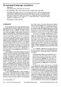
made obstructions on the earthmoving plan; 3) support three-dimensional visualisation; or 4) provide scheduling capabilities. 2. PROPOSED MODEL This paper briefly describes a model designed to automate the above-mentioned functions, and focuses primarily on the automation aspects. Transverse obstructions, such as rivers are considered when developing the workbreakdown structure (WBS). The model stores a list of activities typically encountered in highway construction, and generates the precedence network respecting the job logic. Geographic information systems (GIS) is employed to acquire and analyze spatial data and generate the optimum earthmoving plan using the mass haul diagram. The model automatically generates digital terrain models (DTMs) to represent the original ground topography and underlying soil strata. When estimating quantities of cut and fill, the model accounts for variations in swell and shrinkage factors of soils of these strata. The model is implemented in a prototype software that operates in Microsoft Windows environment. It accepts several input formats and provides graphical and tabular reports. The model is schematically illustrated in Figure 1. It utilises GIS to acquire and analyze spatial data. A knowledge base is employed to define the WBS and generate the precedence network respecting the job logic. Relational database models store: 1) swell and shrinkage factors of common soil types; and 2) available resources. Once the WBS and precedence network have been defined and crews have been assigned to their respective activities, the project can be scheduled. In view of the highly repetitive nature of highway construction, the scheduling engine employs resource-driven scheduling. As the figure shows, the model generates tabular and graphical reports, and generates the optimum earthmoving plan using the mass haul diagram. The main functions of the model are discussed below. 2.1. Data Acquisition and Analysis
2
Figure 2 illustrates the sequence of operations to automate data acquisition and analysis. The model extends the capabilities of the traditional mass haul diagram (Stark and Mayer 1983) to account for: 1) the presence of different soil strata in cut sections; 2) the presence of transverse natural and/or man-made obstructions; and 3) varying degrees of soil compaction. The model generates threedimensional DTMs to represent the original ground topography and underlying soil strata. These DTMs are stored as triangulated irregular networks (TINs) so as to reduce demand on the system’s memory without sacrificing accuracy (Oloufa 1991). An iterative procedure is proposed to generate TIN nodes along contour lines (see Figure 3). Initially, the iteration number (R) and contour line identifier (L) are initialized to unity. Next, the node number (i) and distance from start of contour line (di) are initialised to unity and zero, respectively. If (R=1), the distance along the contour line to the next node, “DiRN”, is set equal to the horizontal component of the perpendicular distance to the nearest contour line. Otherwise (i.e. R>1), DiRN is reduced to half its value in the previous iteration. This process is repeated until nodes are generated along the entire length of the contour line (nested loop 1). The same procedure is applied to generate TIN nodes along remaining contour lines (nested loop 2) enabling the generation of a DTM. Next, the volume of soil contained under that DTM, “VolR”, is computed. If (R=1) then “R” is incremented and the whole process is repeated (loop 1). Otherwise, estimated volumes of soil from the last two iterations are compared. If the change in “VolR” is less than the specified tolerance (default=15%), then the process is complete. Otherwise “R” is incremented and the process is repeated until the required accuracy is attained. Strata profiles can either be: 1) defined by the user, by specifying the strata connectivity between boreholes; or 2) automatically generated by the model, and revised as needed by the user. In the latter case, each soil layer in a borehole is assigned a number, “i”, that
accounts for its sequence from top to bottom, starting with i=1 at ground level. The model assumes that the assigned number for each layer can go up or down by one level between two successive boreholes. If a stratum is not found in neighbouring borehole test results, it is assumed that the stratum tapers linearly to reach a thickness of zero (0) at the location of that borehole. The volume of soil contained between two successive sections in the highway embankment is estimated knowing the end areas and the distance between them. A modification of the average-end-area method proposed by Epps and Corey (1990) is employed. The methodology proposed by Easa (1992) is employed to estimate the volume of soil contained in curved portions of the highway embankment. This methodology requires that end section be simplified, and the procedure proposed by Easa (1989) is employed for that purpose. The model automatically determines which sets of equations to employ when estimating cut and fill volumes. 2.2. Work-Breakdown Structure Transverse obstructions, such as rivers and creeks, play a major role in performing the WBS (Alkass and Harris 1991). There are two types of obstructions: 1) surmountable, where access is granted across the obstruction at an overhead (time and cost); and 2) insurmountable, where no access is granted. Work zones are normally defined based on the locations of insurmountable obstructions, while segments are defined based on the locations of surmountable ones. The model stores a list of activities typically encountered in highway construction and divides activities into work packages based on the locations of transverse obstructions. The resulting WBS is shown in Figure 4. 2.3. Precedence Network The model automatically generates precedence networks defining the construction of new highways, as well as the rehabilitation of
3
existing ones. Generated precedence networks are generated detailing operations along the main project route as well as the construction of: 1) overpasses; 2) transverse overpasses; and 3) interchanges. The model enables the selection of any or all of the stored activities, and the precedence network is generated accordingly. The model also enables the definition of additional activities, along with their precedence relations. 3. COMPUTER IMPLEMENTATION The proposed model is implemented in a prototype software that operates in Microsoft Windows. The software: 1) is user-friendly; 2) generates graphical and tabular output; and 3) enables data exchange with commercially available software. It provides an interface with dialog windows, menus, toolbars and a status bar. In view of its widespread acceptance, ArcView GIS (version 3.1) is employed as the GIS engine, while threedimensional analysis is carried out using ArcView 3D Analyzer. Microsoft Access is employed as the database management system (DBMS). The software accepts a wide variety of input formats, including AutoCAD files, digitized blue prints and GPS data points. It provides three-dimensional visualization of: 1) final highway embankment; 2) ground topography; and 3) underlying soil strata. 4. SUMMARY REMARKS
AND
CONCLUDING
This paper briefly describes a model, designed to automate: 1) spatial data acquisition; 2) the generation of the optimum earthmoving plan; 3) the development of the project’s workbreakdown structure; and 4) the development of precedence network respecting planned job logic. The paper focuses primarily on the automation aspects of the developed model, which employs geographic information systems to compute cut and fill quantities and generate the optimum earthmoving plan. A methodology is proposed to generate digital terrain models representing the original ground terrain and estimate quantities of cut and fill. A relational database stores swell and shrinkage
factors for common soil types, enabling accurate estimation of soil quantities. The model accounts for the presence of transverse obstructions on the work breakdown structure and consequently the proposed earthmoving plan. The model is implemented in a prototype software that operates in Microsoft Windows environment. The model demonstrates the potential of GIS as an emerging tool in acquiring and analyzing spatial data. Using the proposed model can significantly reduce the time and cost required to plan highway construction, while enhancing the accuracy of the developed estimates.
Epps, J. and Corey, M., 1990, “Cut and Fill Calculations by Modified Average-End-Area Method”, Journal of Transportation Engineering, ASCE, Vol. 116, No. 5, pp. 683689. Fan, L., Ho., C. and NG, V., 2001, “A Study of Quantity Surveyors’ Ethical Behaviour”, Construction Management and Economics, E & FN Spon, Vol. 19, pp. 19-36. Herbsman, Z.J., 1987, “Evaluation of Scheduling Techniques for Highway Construction Projects”, Transportation Research Record 1126, National Research Council, Washington, D.C., pp. 110-120.
5. REFERENCES Adeli, H. and Karim, A., 1997, “Scheduling/Cost Optimization and Neural Dynamics Model for Construction”, Journal of Construction Engineering and Management, ASCE, Vol. 123, No. 4, pp. 450-458. Alkass, S. and Harris, F., 1991, “Development of an Integrated System for Planning Earthwork Operations in Road Construction”, Construction Management and Economics, E & FN Spon, Vol. 9, pp. 263-289. Chevallier, N. and Russell, A.D., 2001, “Developing a Draft Schedule Using Templates and Rules”, Journal of Construction Engineering and Management, ASCE, Vol. 127, No. 5, pp. 391-398.
Jayawardane, A. and Harris, F., 1990, “Further Development of Integer Programming in Earthwork Optimization”, Journal of Construction Engineering and Management, ASCE, Vol. 116, No. 1, pp. 18-34. NCHRP (National Cooperative Highway Research Program), 2000, Project Management Information Systems, Synthesis of Highway Practice #282, Transportation Research Board, National Research Council, National Academy Press, Washington, D.C. Oloufa, A.A. 1991. “Triangulation Applications in Volume Calculation”, Journal of Computing in Civil Engineering, ASCE, Vol. 5, No. 1, pp. 103-121.
Easa, S.M., 1989, “Simplifying Roadway Cross Sections Without Reducing Volume Accuracy”, Canadian Journal of Civil Engineering, CSCE, Vol. 16, pp. 483-488.
Siyam, Y.M., 1987, “Precision Sectional Area Calculations on Determination”, Journal of Engineering, ASCE, Vol. 113, No. 151.
Easa, S.M., 1992, “Estimating Earthwork Volumes of Curved Roadways: Mathematical Model”, Journal of Transportation Engineering, ASCE, Vol. 118, No. 6, pp. 834-849.
Stark, R.M. and Mayer, R.H., 1983, Quantitative Construction Management: Uses of Linear Optimization, John Wiley & Sons, Inc, New York.
4
in CrossEarthwork Surveying 3, pp. 139-
Activity list & precedence relations
Acquisition & analysis of spatial data
GUI
Earthmoving plan
Scheduling engine
Graphical output
Figure 1: Proposed model
Generate DTM representing original ground topography Generate strata profiles between borehole locations Generate DTMs representing underlying strata Superimpose highway profile on generated DTMs Generate sections along highway embankment Compute cut and fill quantities between sections Develop optimum earthmoving plan Define scope of earthmoving activity and report to scheduling engine
Figure 2: Procedure for analyzing spatial data
5
Tabular output
Start R=1
Loop 1
L=1
Nested loop 2
i=1 di=0 Yes
Nested loop 1
R=1?
No
DiRN= ┴ler dist to nearest contourline
DiRN= Di(R-1)N/2
di= di-1+DiRN i=NL?
L=L+1
i=i+1 No
Yes
R=R+1
L=NumL? No
No
Yes Compute VolR
R>1? Yes
No
Abs(VolR-VolR-1) < Tol ? VolR Yes End
Figure 3: Developed algorithm to generate TIN nodes
Project Work zone 1
Work zone i
Work zone i+1
Segment j Section k Unit k1
Unit kj
Unit kn
Figure 4: Proposed WBS
6