2014 Ninth International Conference on Ecological Vehicles and Renewable Energies (EVER)
Automated Design of DC-Excited Flux-Switching In-Wheel Motor using Magnetic Equivalent Circuits Yang Tang
Johannes J. H. Paulides
Elena A. Lomonova
Eindhoven University of Technology Den Dolech 2, 5612 AZ Eindhoven, The Netherlands Email:
[email protected]
Eindhoven University of Technology Den Dolech 2, 5612 AZ Eindhoven, The Netherlands Email:
[email protected]
Eindhoven University of Technology Den Dolech 2, 5612 AZ Eindhoven, The Netherlands Email:
[email protected]
Abstract— DC-excited flux-switching motor (DCEFSM) is increasingly considered as a candidate traction motor for electric vehicles due to its robust and magnet-free structure with relatively high torque density and extendable speed range. In this paper, an automated design tool based on nonlinear magnetic equivalent circuits (MEC) is initiated for the preliminary design of a 6-statorsegment 5-rotor-tooth DCEFSM used for indirect drive inwheel traction of electric cars. This MEC-based design tool is configured using a versatile manner that reduces the workload involved in constructing elaborate MEC models. Using this design tool, parameter sweeping is performed on the split ratio and back iron height of the motor to maximize the torque production with different constraints of flux density. The accuracy of this design tool is validated using finite element analysis (FEA). Keywords—in-wheel
automated design, incidence matrix. I.
traction, flux-switching motor, magnetic equivalent circuit,
INTRODUCTION
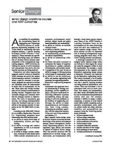
With the development of electric vehicle technology, in-wheel traction becomes an actual concept for the vehicle design. In this concept, traction motors are placed inside or aside the wheels of an electric vehicle, hence the differential and mechanical axes can be removed. The drivetrain is thus simplified, resulting in extra space and greater freedom for the vehicle design [1], [2]. However, in-wheel traction raises the challenge for the motor design. On the one hand, in-wheel motors increases the unsprung mass, which can potentially reduce the ride comfort [3]. Thus, the electric motors designed for this application is expected to be lightweight. On the other hand, driving the vehicle directly from the wheel requires high torque capability of the in-wheel motor, which implies a large motor size [4]. The conflict between the weight limit and the high torque requirement can be resolved with an indirect drive in-wheel module [5], shown in Fig. 1b, in which the traction motor is indirectly driving the wheel through a gearbox. By this means the
978-1-4799-3787-5/14/$31.00 © 2014 IEEE
torque requirement for the traction motor is lowered, thus the motor size is reduced and the unsprung mass can be maintained.
(a)
(b)
Fig. 1 In-wheel traction: a) electric car with four-wheel drive inwheel motors; b) indirect drive in-wheel module
The electric motor selected for this indirect drive inwheel traction is required to have high torque density with a wide speed range. Flux-switching motors (FSM) are increasingly considered because they combine the advantages of ruggedness of switched reluctance motors (SRM) and high torque density of permanent magnet synchronous motors (PMSM) [6]. However, with permanent magnet excitation this motor meets difficulties in field weakening, leading to a limited speed range. This problem can be solved by replacing permanent magnets with DC field windings [7], shown in Fig. 2. This additional advantage in field weakening makes dc-excited flux-switching motor (DCEFSM) a promising candidate for this application of indirect drive in-wheel traction [8]. To design such an electric motor with high torque density there is a real requirement for automated design tools that can assist experienced designers. Software based on numerical methods, such as finite element analysis (FEA), is not preferred for this purpose as it provides little insight in the parameters and requires a significant computational time despite of relatively high accuracy [9]-[11]. In contrast, certain analytical methods, such as Fourier analysis and magnetic charge modeling, are relatively faster in computing. However, they are less
accurate in solving nonlinear magnetic problems resulting from magnetic saturation [12]-[15]. FF+
F+
θ
θ r
r F-
Two categories of elements exist in a MEC model: passive elements as reluctances or permeances and active elements as sources. Sources can be further classified into mmf sources and flux sources. Current-carrying coils are usually modeled as mmf sources. Permanent magnets are modeled as mmf sources with reluctances in series or flux sources with reluctances in parallel.
FF+
(a) FSPMM
(b) DCEFSM
Fig. 2 Cross-section of 6-stator-segment 5-rotor-tooth flux-switching motors: a) flux-switching permanent magnet motor (FSPMM) and b) dc-excited flux-switching motor (DCEFSM).
Magnetic equivalent circuits (MEC) provide a good compromise between computational time and accuracy. Hence, they have been extensively used for analyzing subsystems of electrical machines and actuators which are prone to saturation, e.g. the stator and rotor teeth or backiron [16]-[23]. However, they are generally avoided when a method is required to automate the motor design, due to difficulties in constructing large-scale global MEC models for differently parameterized electrical motors. To pave the way for the development of MEC-based motor design software, authors of this paper initiate a study on a versatile manner to apply model reduction to the construction of large-scale global MEC. In this manner, large-scale global MEC models of electrical motors are constructed using a limited number of smallscale MEC modules that can be easily assembled, adapted and replaced. Hence, the workload involved in constructing and adapting the global MEC model is greatly reduced. Using this model reduction manner, a MEC-based automated design tool is synthesized to optimize the design of a 6/5 DCEFSM. The accuracy of this design tool is validated using finite element analysis (FEA). II.
MAGNETIC EQUIVALENT CIRCUIT MODEL REDUCTION
A. Magnetic equivalent circuits
The MEC method is based on analogies between electric and magnetic circuits [9], [24], [25]. This method identifies flux tubes by lumping the magnetic fields into a limited number of elements. Within a flux tube, an approximation is identified that the flux lines are perpendicular to its head faces while not cutting its sides, as shown in Fig. 3. The flux through a flux tube is assumed to be constant with only two possible directions. The head faces are thus magnetic equipotential planes.
(a)
(b)
Fig. 3. Flux tubes with a) identical flux lines and b) identical crosssection.
B. Principle of model reduction
The major difficulty in using the MEC method for the automated design of electric motors arises from the workload involved in two aspects: the construction of a relatively large-scale global MEC model and the repetitive adaption of this model. The proposed model reduction manner simplifies this problem in both aspects. On the one hand, the large-scale global MEC model can be assembled using a number of MEC modules representing different parts of the electric motor. These MEC modules are repeating in the space domain due to the repetitive structure of machine parts, e.g. MEC modules for stator segments or rotor teeth, or the periodic variation of magnetic field, e.g. MEC modules for the airgap. Therefore, only a limited number of different MEC modules are needed to construct the MEC model for the whole machine. On the other hand, to simplify the necessary adaption of the global MEC model the rotor positions can be divided into a discrete and minimized number of states. In each state, the topology of the global MEC model is assumed to be identical, despite that certain permeance values may be adapted in synchronism with the rotor position. The global MEC model needs to be reconstructed only when this position state shifts, hence minimizing the number of reconstruction times. This model reduction procedure is illustrated in the flowchart as shown in Fig. 4. Saturation can be taken into account by iteratively solving the MEC model to identify the applicable relatively permeability used for the flux tube, which is included in the “solve the global MEC” procedure.
φ – flux through each branch (n×1 vector), E – mmf source in each branch (n×1 vector), Λ – permeance of each branch (n×n diagonal matrix), R – reluctance of each branch (n×n diagonal matrix).
Input (e.g. geometric parameters, magnetic properties, etc.)
Define MEC modules
Define position states
Assemble MEC modules
Select the position state
Adapt permeance values
According to Kirchhoff’s Circuit Laws, following equations can be derived: U = At ⋅ V , A ⋅φ = 0,
(2) (3)
U = R ⋅ φ + E = Λ −1 ⋅ φ + E . (4) Therefore, with given A, Λ, and E, the magnetic potentials can be solved as: V = ( A ⋅ Λ ⋅ At ) ⋅ ( A ⋅ Λ ⋅ E ) . -1
Solve the global MEC (iteratively for saturation)
θ k +1 = θ k + Δθ Yes
Within a state?
No Yes
Within a period?
Using the incidence matrix method, the construction of a large-scale circuit with connecting the nodes of smallscale circuits can also be mathematically represented. Assume that there are two circuits: C1 with m1 nodes and n1 branches and C2 with m2 nodes and n2 branches. The incidence matrices, permeance matrices, and source vectors of these two circuits are denoted as A1 and A2, Λ1 and Λ2, and E1 and E2, respectively. If a circuit C0 is configured by connecting the ith node of C1 with the jth node of C2, the incidence matrix A0, reluctance matrix R0, and source vector E0 of C0 can be obtained in the following manner: •
No Output (e.g. magnetic potentials, reluctances, fluxes, etc.)
•
Fig. 4. Flowchart of the MEC model configuration and solution procedure for automated design of electric motors.
C. Solving method model, the global MEC model is realized using the incidence matrix method [26].
For a circuit with m nodes and n branches, its incidence matrix A is an m×n matrix in which:
A – incidence matrix (m×n matrix), V – magnetic potential on each node (m×1 vector), U – mmf drop across each branch (n×1 vector),
To obtain A0, a new matrix Am is first created by simply merging the incidence matrices of C1 and C2 as:
0 ⎞ ⎛A Am = ⎜ 1 (6) ⎟ , ⎝ 0 A2 ⎠ The incidence matrix A0 can thus be derived by adding the values of the (m1+j)th row of Am to its ith row and removing the (m1+j)th row afterward, i.e.: ⎧A m ( k , n) + A m ( m1 + j , n), if k = i; ⎪ A 0 ( k , n) = ⎨A m ( k , n), if k ≠ i and k < m1 + j; (7) ⎪A ( k + 1, n ), if k > m + j. 1 ⎩ m Using this equation, the ith node of C1 is connected to all the branches that the jth node of C2 was connected to. Additionally, the jth node of C2 does not exist anymore in Cm as there is no mmf drop between it and the ith node of C1, or in other words, the two nodes become one, as shown in Fig. 5.
To achieve an automated manner to construct the MEC
⎧1, if branch j begins from node i; ⎪ Aij = ⎨−1, if branch j ends to node i; (1) ⎪0, if branch j is not connected to node i. ⎩ Variables of this circuit can be further defined in the form of matrix or vector, listed as follows:
(5)
•
The branches in C1 and C2 do not change after merging, thus the permeance matrix Λ0 and the source vector E0 of the circuit C0 can simply be obtained as:
0 ⎞ ⎛Λ Λ0 = ⎜ 1 (8) ⎟, ⎝ 0 Λ2 ⎠ ⎛E ⎞ E0 = ⎜ 1 ⎟ (9) ⎝ E2 ⎠ Therefore, the incidence matrix, permeance matrix, and mmf source vector of a large-scale circuit can be obtained by merging those matrices and vectors of smallscale circuits. By this means, the global MEC model of an electric motor can be fast constructed and solved based on pre-defined MEC modules.
• Stator MEC modules In this paper, a stator MEC module for the 6/5 DCEFSM is defined as the MEC model of a stator segment, i.e.: a sixth of the stator, as shown in Fig. 7a. In this MEC module, the excited coil in the middle slot of the stator segment is modeled as an mmf source Fc. The flux paths in the stator tooth and stator back iron are modeled as different flux tubes with permeances Pst1, Pst2, Psi1, and Psi2. The leakage fluxes in the slot and outside the stator are also considered and modeled as two flux tubes with permeances Psl1 and Psl2, respectively, as shown in Fig. 7a. The types of flux tubes selected from Fig. 6 for the permeance calculation are summarized in Table I. The topology of this MEC module is shown in Fig. 7b, where the nodes and branches are numbered in Arabic and Roman numerals, respectively.
I
II
III IV V VI
1 ⎡1 0 0 0 0 0⎤ 2 ⎢⎢ −1 −1 1 0 0 0 ⎥⎥ 3 ⎢0 1 0 0 0 0⎥ ⎢ ⎥ A m = 4 ⎢ 0 0 −1 0 0 0 ⎥ 5 ⎢0 0 0 1 0 0⎥ ⎢ ⎥ 6 ⎢ 0 0 0 −1 −1 1 ⎥ ⎢ 7 ⎢ 0 0 0 0 1 0 ⎥⎥ 8 ⎢⎣ 0 0 0 0 0 −1⎥⎦
I
A0 =
1 2 3 4 5 6 7
II
III IV V VI
⎡1 0 0 0 0 0⎤ ⎢ −1 −1 1 0 0 0 ⎥ ⎢ ⎥ ⎢0 1 0 0 0 0⎥ ⎢ ⎥ ⎢ 0 0 −1 0 1 0 ⎥ ⎢0 0 0 1 0 0⎥ ⎢ ⎥ ⎢ 0 0 0 −1 −1 1 ⎥ ⎢ 0 0 0 0 0 −1⎥ ⎣ ⎦
Fig. 5. Example of the circuit merging using incidence matrices
III.
MEC-BASED AUTOMATED DESIGN TOOL
A. MEC modules
For the 6/5 DCEFSM, six types of flux tubes are identified to construct the MEC model, shown in Fig. 6.
It is worth noting that the actual magnetic flux paths in the stator vary with rotor position. However, to simplify the modeling problem, this variation is neglected as the permeability of the ferromagnetic material is relatively large under non-saturated conditions.
Psl1
Psi1
Fc
Pst1
Pst1 Pst 2
Psi1
Psi 2
Psl 2
Pst 2
(a) MEC model
r1
r2
r1
r2
r1 r2 Fig. 6. Flux tubes and their permeances: a) P = µLθ/ln(r2/r1); b) P = µLln(r2/r1)/θ; c) P = µLx/h; d) P = 2µL·ln[1+ πx/(πr+2h)]/π; e) P = µL·ln[1+ 2πx/(πr1+πr2+2h)]/π; f) P = 2µLx/(πw+2h).
(b) Topology Fig. 7. Stator MEC module of the 6/5DCEFSM
• Rotor MEC modules A rotor MEC module for the 6/5 DCEFSM is defined as the MEC model of a fifth of the rotor, as shown in Fig. 8a. In this module, the flux paths in the rotor tooth and rotor back iron are modeled as different flux tubes with permeances Prt and Pri, respectively. The types of flux tubes selected from Fig. 6 for the permeance calculation are summarized in Table I.
states, corresponding to eight intervals divided from a stator segment, shown in Fig. 8. A different airgap MEC module is used only when the rotor tooth enters a different interval. In addition, with respect to the center axis of the excited coil, the four states on the left side, numbered from 1 to 4, are symmetric to the four on the right side, numbered from -1 to -4, thus only four different airgap MEC modules are needed. A stator segment
The topology of this MEC module is presented in Fig. 8b, where the nodes and branches are numbered in Arabic and Roman numerals, respectively.
4 3 2 1 -1 -2 -3 -4
θij
Prt r θ
Pri
Pri Fig. 9. Interval division of a stator segment for the state definition of rotor tooth position (a) MEC model
The flux tubes of the four airgap MEC modules are shown in Fig. 10a, 11a, 12a, and 13a, respectively, in which θij is the angle between the central axes of the ith rotor tooth and the jth stator segment. The types of flux tubes selected from Fig. 6 for the permeance calculation are summarized in Table II. In these modules, each permeance is expressed as a function of the angle θij. The MEC models for each airgap MEC module are presented in Fig. 10b, 11b, 12b, and 13b, respectively. In addition, the topologies of these MEC models are highlighted in Fig. 10c, 11c, 12c, and 13c.
(b) Topology Fig. 8. Rotor MEC module of the 6/5 DCEFSM
TABLE I: TYPES OF FLUX TUBES IN THE STATOR AND ROTOR MEC MODULES
Pst1,2 Psi1,2 Psl1 a b e
Psl2 a
Prt b
Pri a
• Airgap MEC modules An airgap MEC module is defined as the MEC model for the airgap area around a rotor tooth. The airgap magnetic field varies in synchronous with the rotor position, thus the airgap MEC module needs to be adapted for different rotor positions. To limit the number of varieties of airgap MEC modules, positions of a rotor tooth are grouped into eight
TABLE II TYPES OF FLUX TUBES IN DIFFERENT AIRGAP MEC MODULES
j Pi,j P1,j P2,j P3,j P4,j
1
2
3
4
5
6
7
8
9
10
11
d d d d
e f f f
d e e d
c d d d
d c c c
d d e d
f f f e
d f d f
c d -
d c -
d -
B. Global MEC models
The global MEC model of this 6/5 DCEFSM at a certain rotor position is consisting of six stator MEC modules (S1 – S6), five rotor MEC modules (T1 – T5), and five airgap MEC modules (A1 – A5). The type of each airgap MEC module is decided according to the distance between the corresponding rotor tooth and the
θij
θ ij
P1,4 P1,5 P1,6P1,7 P1,3 P1,1
P2,4 P1,8
P1,9 P1,10
P2,5
P1,2
P2,1
P2,9
P2,2
r
P2,11
θ
(a)
P1,2 P1,3 P1,4 P1,5
P2,10
r
θ
P1,1
P2,6 P2,7 P2,8
P2,3
P1,6 P1,7 P1,8
(a)
P1,9 P1,10
P2,1
P2,2
P2,3 P2,4 P2,5 P2,6
(b)
(b)
(c)
(c)
P2,7 P2,8 P2,9
P2,10 P2,11
Fig. 10. Airgap MEC module 1: a) flux tubes in the airgap while a rotor tooth travels in interval 1; b) detailed magnetic equivalent circuit; c) topology of airgap MEC module 1.
Fig. 11. Airgap MEC module 2: a) flux tubes in the airgap while a rotor tooth travels in interval 2; b) detailed magnetic equivalent circuit; c) topology of airgap MEC module 2.
nearest stator segment, as shown in Fig. 10 – 13. It is worth noting that the divisions of stator segment are different when different currents, i.e. DC field current or three-phase AC current, are concerned. Hence, two sets of global MEC models are used to separately calculate the flux in the motor with only excitation in the DC field winding or in the three-phase AC winding, as the examples shown in Fig. 14 and Fig. 15. These two sets of models are similar, however, with a phase shift due to the different starting points of stator segments.
global MEC models to approach a unified value of permeability.
When the magnetic property of the motor is assumed linear, the total flux in the motor can be calculated as summation of fluxes calculated in each set of model. When magnetic saturation is concerned, iterations are performed synchronously on the solving processes of both
C. Torque calculation
The eletromagnetic torque of this motor can be approximately calculated using the phase current and the phase flux-linkage obtained from the global MEC models: 3 ˆ ˆ Ea ia = Teω 2 3 3 ˆ ˆ Te = Eˆ a iˆa / ω = N r Ψ af ia 2 2
(10) (11)
θij
P3,3 P3,4
P3,5
θ ij
P4,8
P3,7
P3,2
P3,6
P3,1
P4,1
P4,3 P4,4 P4,5P4,6 P4,2
P4,7
P4,7
P3,8
r
r
θ
θ
(a)
P3,1
P3,2
P3,3
P4,8
P3,4
(a)
P3,5
P3,7
P4,7
P3,6
P4,8
P4,7 P4,1 P4,2 P4,3
P4,4 P4,5 P4,6
P4,8
P3,8 (b)
(b)
(c)
(c)
Fig. 12. Airgap MEC module 3: a) flux tubes in the airgap while a rotor tooth travels in interval 3; b) detailed magnetic equivalent circuit; c) topology of airgap MEC module 3.
Fig. 13. Airgap MEC module 4: a) flux tubes in the airgap while a rotor tooth travels in interval 3; b) detailed magnetic equivalent circuit; c) topology of airgap MEC module 4.
Fig. 14. Topology of the global MEC model of the 6/5 DCEFSM at a certain rotor position with only current excitation in the DC field winding.
Fig. 15. Topology of the global MEC model of the 6/5 DCEFSM at a certain rotor position with only current excitation in the threephase AC winding.
IV.
AUTOMATED DESIGN OF AN IN-WHEEL DCEFSM
A. Model validation
Using the presented MEC modules and solving methods, a MEC-based automated design tool is synthesized for design of 6/5 DCEFSM. To validate the accuracy of this design tool, analyses are performed on three differently dimensioned 6/5 DCEFSM models, shown in Fig. 16, using both the nonlinear global MEC and the finite element method (FEM). The dimensions of these three motor models are summarized in Table III. The rms values of the current density in both AC and DC windings are set as 10A/mm2, hence a certain extent of magnetic saturation is expected.
this MEC-based design tool. In this strategy, the global MEC is iteratively solved only once with a certain rotor position to obtain a reasonable estimation of the average permeability for various motor parts. The derived permeability is then implemented to the global MECs with other rotor positions, thus the computational time is minimized. This strategy is more accurate when the magnetic source is stable, i.e. permanent magnets or DC current, resulting in a relatively stable overall level of saturation in the motor. However, when the dominant magnetic source is AC current, the average saturation level of the motor varies greatly with the alternating current, hence the average permeability estimated at the certain rotor position becomes less accurate for other rotor positions. In this case, the accuracy can be improved by iteratively solving the global MEC for each rotor position, at the price of a longer computational time.
Fig. 16. Cross-sections of the three DCEFSM models.
TABLE III DIMENSIONS OF THE THREE MOTOR MODELS
Description Stack length L Stator outer diameter Dso Stator back iron height hsi Stator slot depth hs Rotor outer diameter Dro Airgap length δ
M1 90 120 7.9 21.7 45 1
M2 90 240 15.9 43.5 90 1
M3 90 360 23.8 65.2 180 1
Unit mm mm mm mm mm mm
Fig. 17. Results of phase flux linkage of the three motor models with current excitation only in the DC field winding, in which the current density Jf = 10A/mm2.
The results of phase flux linkage of the three models obtained using the two methods are compared, shown in Fig. 17 – Fig. 19. The MEC results generally present a good agreement with the FEM results with various motor dimensions, hence the accuracy of the constructed design tool is validated. The most visible mismatch appears in the result of phase flux linage of M3 with current excitation only in the AC windings, shown in Fig. 18. In this case, the absolute values of the MEC result are lower than those of the FEM result at a number of rotor positions. Nevertheless, the amplitudes of the two results are still close. The underestimation of the flux linkage in the MEC result is resulting from the nonlinear solving strategy adopted by
Fig. 18. Results of phase flux linkage of the three motor models with current excitation only in the three-phase AC winding, in which the current density Ja = 10A/mm2, rms.
TABLE IV OPTIMAL DESIGN PARAMETERS OBTAINED USING THE MECBASED AUTOMATED DESIGN TOOL
Magnetic flux density constraint Bst, Bsi (T) 0.8 1.0 1.2 1.4 1.6 1.8 Fig. 19. Results of phase flux linkage of the three motor models with current excitation in both the DC field winding and the three-phase AC winding, in which the current density Jf = Ja , rms = 10A/mm2.
B. In-wheel motor design using the automated design tool
A prototype of the indirect drive in-wheel drive module shown in Fig. 1b is designed and manufactured based on the specification of Volkswagen Lupo 3L, as shown in Fig. 20.
(a) Prototype
Optimal split ratio Dro/Dso 0.56 0.52 0.48 0.45 0.42 0.40
Optimal stator back-iron height hsi (mm) 10.2 9.4 8.8 8.2 7.6 7.2
The obtained results of split ratio and stator back-iron height are further implemented into the FEA model. Figure 21 shows the comparison of the FEA results of average torque and magnetic flux density and the results derived from the MEC-based design tool. It can be seen that the average torque values calculated using the MEC method fairly match the FEA results, hence the feasibility of using this MEC-based design tool for preliminary design is proved.
(b) VW Lupo 3L
Fig. 20 Prototype of the indirect drive in-wheel module for Volkswagen (VW) Lupo 3L.
(a)
A 6/5 DCEFSM is chosen as the traction motor. Based on the prototype structure, the stator outer diameter Dso of the motor is constrained at 127.5mm, and the stack length L is constrained at 90mm. Using the constructed MECbased design tool, optimization is performed to determine the split ratio (Dro/Dso) and the stator back-iron height hsi that provides the maximum average torque with constrained magnetic flux densities in stator teeth and back iron. Table IV shows the optimization results of split ratio and stator back-iron height with respect to different constraints of magnetic flux density in stator teeth Bst and stator back iron Bsi. For this preliminary design, the current densities in both of the three-phase ac winding and the dc field winding are assumed as 5A/mm2, rms.
(b) Fig. 21 Comparison of FEA and MEC results: a) magnetic flux densities in the stator; b) average torque with different constraints of magnet flux density.
V.
CONCLUSION
Dc-excited flux-switching motors (DCEFSM) are a strong candidate for the in-wheel traction of electric vehicles due to their robust and magnet-free structure with relatively high torque density and extendable speed range. To design a DCEFSM with high torque density, an automated design tool is required. Magnetic equivalent circuits (MEC) were extensively used for the analysis of specific parts of electrical machines which are prone to saturation. However, this method is seldom considered for the automated design of the full machine because of the difficulties in constructing and adapting a large-scale MEC model. In this paper, a model reduction manner is proposed to reduce the workload involved in the MEC modeling of electrical machines. Using this manner, large-scale global MEC models of a whole motor are assembled using small-scale MEC modules that represent different machine parts. Rotor positions are also grouped into a limited number of position states, hence minimizing the number of varieties of the global MEC topology. The construction and fast solution of the MEC model are realized using the incidence matrix method. Using this model reduction manner, a MEC-based automated design tool is initiated and used to design a 6stator-segment, 5-rotor-tooth DCEFSM for the application of indirect drive in-wheel traction of electric cars. With assistance of this design tool, optimization is performed to determine the split ratio and the stator back-iron height that provides the maximum average torque with different constraints of flux density. The average torque estimated using the MEC-based design tool fairly match the FEA results, hence the accuracy of this MEC-based design tool is validated.
References [1] [2] [3]
[4]
[5]
[6]
Z. Q. Zhu, D. Howe, “Electrical machines and drives for electric, hybrid, and fuel cell vehicles”, Proceedings of the IEEE, Vol.95, No.4, April 2007. M. Ehsani, Y. Gao, and J. M. Miller, “Hybrid electric vehicle: architecture and motor drives”, Proceedings of the IEEE, Vol. 95, No.4, April 2007 R. Vos, I. J. M. Besselink, H. Nijmeijer, “Influence of in-wheel motors on the ride comfort of electric vehicles”, Proceedings of the 10th International Symposium on Advanced Vehicle Control (AVEC10), pp. 835-840, Loughborough, United Kingdom, 22-26 August 2010. E. A. Lomonova, E. V. Kazmin, Y. Tang, J. J. H. Paulides, “In-wheel PM motor : compromise between high power density and extended speed capability”, COMPEL: The International Journal for Computation and Mathematics in Electrical and Electronic Engineering, 30(1), 98-116, 2011. Y. Tang, J. J. H. Paulides, I. J. M. Besselink, F. Gardner, E. A. Lomonova, “Indirect drive in-wheel system for HEV/EV traction”, Proceedings of the 27th International Electric Vehicle Symposium and Exhibition (EVS’27), Barcelona, Spain, 17-21 November, 2013. Y. Tang, T. E. Motoasca, J. J. H. Paulides, E. A. Lomonova, “Comparison of flux-switching machines and permanent magnet
[7] [8] [9] [10] [11]
[12]
[13]
[14] [15]
[16]
[17]
[18]
[19] [20] [21]
[22]
[23]
[24] [25] [26]
synchronous machines in an in-wheel traction application”, Proceeding of EVER’11 Monaco, pp. 1-10, Monaco, 2011. S. E. Rauch and L. J. Johnson, “Design pinciples of flux-switch alternators,” Transactions of the American Institute of Electrical Engineers (AIEE Trans.), vol. 74, no. 3, pp. 1261–1268, 1955. Y. Tang, T. E. Motoasca, J. J. H. Paulides, and E. A. Lomonova, ‘‘Fluxswitching machine with dc excitation,’’ IEEE Transactions on Magnetics, vol. 48, no. 11, pp. 3583---3586, November 2012. V. Ostovic, “Dynamics of saturated electric machines”, Berlin Heidelberg, Germany: Springer-Verlag New York Inc., 1989. M. V. K. Chari, G. Bedrosian, J. D’Angelo, “Finite element applications in electrical engineering”, IEEE Trans. Magn., Vol. 29, No. 2, Mar. 1993. W. L. Soong, D. A. Staton, T. J. Miller, “Validation of lumped-circuit and finite-element modeling of axially-laminated brushless machines”, in Proceedings of the 6th International Conference Electrical Machines and Drives, pp. 85-90, 1993. B. L. J. Gysen, E. Ilhan, K. J. Meessen, J. J. H. Paulides, and E. A. Lomonova, “Modeling of flux switching permanent magnet machines with Fourier Analysis”, IEEE Trans. Magn., Vol. 46, No. 6, pp. 14991502, 2010. B. L. J. Gysen, K. J. Meessen, J. J. H. Paulides, and E. A. Lomonova, “General formulation of the electromagnetic field distribution in machines and devices using Fourier Analysis”, IEEE Trans. Magn., Vol. 46, No. 1, Jan. 2010. E. Ilhan, B. L. J. Gysen, J. J. H. Paulides, and E. Lomonova, “Analytical hybrid model for flux-switching permanent magnet machines”, IEEE Trans. Magn., 46(6), 1762-1765, 2010 E. Ilhan, J.J.H. Paulides, and E. Lomonova, “Fast torque estimation of in-wheel parallel flux switching machines for hybrid trucks”, COMPEL: The International Journal for Computation and Mathematics in Electrical and Electronic Engineering, 31(1), 40-53, 2012. A. V. Lebedev, E. A. Lomonova, P. G. van Leuven, J. Steinberg, D. A. H. Laro, “Analysis and initial synthesis of a novel linear actuator with active magnetic suspension”, Conference record of the 2004 IEEE Industry Application Conference / 39th IAS Annual Meeting, pp. 21112118, Vol. 3, 2004. J. L. G. Janssen, J. J. H. Paulides, E. A. Lomonova, A. J. A. Vandenput, “Analysis of a variable reluctance permanent magnet actuator”, Conference record of the 2007 IEEE Industry Applications Conference / 42nd IAS Annual Meeting, pp. 502-509, September, 2007. Z. Q. Zhu, Y. Pang, D. Howe, S. Iwasaki, R. Deodhar, and A. Pride, “Analysis of electromagnetic performance of flux-switching permanentmagnet machines by nonlinear adaptive lumped parameter magnetic circuit model”, IEEE Trans. on Magnetics, Vol. 41, No. 11, Nov. 2005. J. Farooq, S. Srairi, A. Djerdir, A. Miraoui, “Use of permeance network method in the demagnetization phenomenon modeling in a permanent magnet motor”, IEEE Trans. Magn., Vol. 42, No. 4, Jan. 2006. E. C. Lovelance, T. M. Jahns, J. H. Lang, “A saturating lumpedparameter model for an interior PM synchronous machine”, IEEE Trans. Ind. Appl., Vol. 38, No. 3, pp. 645-650, September/October 2002. M. Cheng, K. T. Chau, C. C. Chan, E. Zhou, X. Huang, “Nonlinear varying-network magnetic circuit analysis for doubly salient permanentmagnet machines”, IEEE Trans. Magn., Vol. 36, No. 1, pp. 339-348, January, 2000. K. Nakamura, K. Kimura, O. Ichinokura, “Electromagnetic and motioncoupled analysis for switched reluctance motor based on reluctance network analysis”, Journal of Magnetism and Magnetic Materials, Vol. 50, Iss. 5, pp. 1309-1312, 2005. A. Chen, R. Nilssen, and A. Nysveen, “Analytical design of a hightorque flux-switching permanent magnet machine by a simplified lumped parameter magnetic circuit model”, XIX International Conference on Electrical Machines ( ICEM), Rome, 2010. H. C. Roters, “Electromagnetic devices”, New York: J. Wiley & Sons, Inc; London: Chapman & Hall, Limited, 1941 J. Makarovic, “Lightweight positioning: design and optimization of an actuator with two-controlled degrees of freedom”, Ph.D. dissertation, Eindhoven University of Technology, the Netherlands, 2006. L. O. Chua and P. M. Lin, ‘‘Computer-aided analysis of electronic circuits-----algorithms and computational techniques’’, Englewood Cliffs, NJ: Prentice-Hall, 1975.