Automated diffraction tomography combined with electron precession: a new tool for ab initio nanostructure analysis Ute Kolb*, Tatiana Gorelik, Enrico Mugnaioli Institut für Physikalische Chemie, Johannes Gutenberg-Universität Mainz, Welderweg 11, D55099 Mainz, Germany ABSTRACT Three-dimensional electron diffraction data was collected with our recently developed module for automated diffraction tomography and used to solve inorganic as well as organic crystal structures ab initio. The diffraction data, which covers nearly the full relevant reciprocal space, was collected in the standard nano electron diffraction mode as well as in combination with the precession technique and was subsequently processed with a newly developed automated diffraction analysis and processing software package. Non-precessed data turned out to be sufficient for ab initio structure solution by direct methods for simple crystal structures only, while precessed data allowed structure solution and refinement in all of the studied cases. INTRODUCTION The rapidly developing nanotechnology urgently needs analytical tools to characterize nano-volumes. The crystalline structure of a material is a principal key for understanding its properties and therefore is the most desired piece of information. Well developed methods for structure analysis by X-ray single crystal diffraction are established and routinely used in many laboratories. Single crystal X-ray analysis requires crystals with a size of at least about 1 mm3. Powder X-ray diffraction can access significantly smaller crystals but indexing and subsequent structure solution is often problematic due to peak overlap, the presence of additional phases, and a preferred orientation. Furthermore, the problem of peak overlap is particularly enhanced due to crystal-size driven peak broadening for nanocrystalline materials. High resolution transmission electron microscopy (HRTEM) is traditionally used for nanostructural investigations. Extrapolating three-dimensional (3D) structural information from images requires special tomographic techniques, which are typically not optimized for electron beam sensitive materials, such as inorganic complex structures (i.e. zeolites) and organic crystals, which cannot sustain the high electron dose needed to collect the data from nano-volumes. While strong efforts were dedicated in recent years for the construction of aberration correctors in order to achieve sub-Ångstrom resolution in imaging [1], the usage of the equivalent information in reciprocal space, already providing such a resolution and easily available in any transmission electron microscope (TEM), is not so well developed. Electron diffraction can probe volumes down to 20-30 nm in diameter, delivering 3D sub-Ångstrom structural information with good signal-to-noise ratio. Nevertheless, there are only a few software packages using low index zone axis patterns [2] and no hardware or formalism for dealing with patterns that were recorded though a tilt around an arbitrary axis available so far. Underdeveloped diffraction instrumentation and the absence of processing routines are major reasons for the electron diffraction technique to be inferior to modern X-ray diffraction techniques. Traditionally, after a suitable crystal has been selected in the TEM imaging mode, a diffraction pattern can be recorded by switching into the diffraction mode. After the crystal has been oriented with a low index axis along the goniometer axis, a series of prominent diffraction patterns (typically of low index crystallographic zones) can be recorded by tilting it around this axis. Since the tilt steps between the single crystal patterns are known, a 3D network of reflections can be obtained, from which the lattice parameters of the structure can be calculated [3].
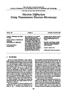
While the unit cell determination using electron diffraction is commonly accepted as a reliable technique that dates back to the 1960s [4], the employment of electron diffraction intensities for structure determinations is still controversial. Electrons, interacting with matter some orders of magnitude stronger than X-rays, tend to scatter several times while traversing through a specimen. Multiple diffraction events modify the final intensities of the reflections, so that such data cannot straightforwardly be used for structure solution anymore. These events are denoted as dynamical effects and usually are stronger in low index diffraction patterns, which are typically used during diffraction data collection via manual tilt series. Recently, the precession electron diffraction (PED) technique was developed as an approach to reduce dynamical effects in electron diffraction patterns [5]. This method is based on the precession of the incident primary electron beam which is inclined away from the optical axis of the TEM. A diffraction pattern recorded in this mode is the sum of patterns produced by the precessing beam sequentially. The intensities of the reflections are integrated throughout the (reciprocal) volume covered by the precessing Ewald sphere and show reduced dynamic diffraction effects. Although manually collected electron diffraction tilt series are rather poor and suffer from dynamical diffraction effects, some ab initio structure solutions were successfully undertaken on the basis of such data [6]. Each of the structure solutions published is a very impressive investigation, but none of the solution paths proposed so far can be used routinely and provides reproducible results for different classes of materials. AUTOMATED DIFFRACTION TOMOGRAPHY Recently an automated (hardware) module for electron diffraction data collection and processing (software) was developed in our research group ([7], [8]). Since the module is based on a collection of diffraction patterns at different tilt angles during specimen tilt, similar to how it is done in real space tomography, the method is called automated diffraction tomography (ADT). ADT principle The principle of the method is sampling the reciprocal space in small steps without any prior information on the orientation of the crystal. The only essential requirement is that the data is collected from the same crystal. In such a way high index crystallographic zones are typically recorded through a tilt around an arbitrary axis. As the information about the angular relationship between the diffraction patterns is available, the three-dimensional reciprocal volume can be reconstructed. Figure 1 shows a schematic sketch of the reciprocal space of a crystal during the ADT data collection process.
Fig. 1: Schematic sketch of the reciprocal space of a crystal during the ADT data acquisition process. The solid black lines correspond to the Ewald sphere positions for ADT pattern collection: the related diffraction patterns include the black segments. The precession mode integrates the data also between the tilting steps; the dotted lines stand for the borders of the PED integrated volumes at the optimal precession angle.
For simplicity, the reciprocal lattice is sketched here stationary, while the Ewald sphere, shown partly for three positions in Figure 1, is considered as moving with respect to it for each tilt step. Alternatively, one may consider the incident precessing primary electron beam as always creating the same hollow cone of illumination and the reciprocal crystal lattice rotating when the crystal is tilted in real space. As the reflections have a physical size, the Ewald sphere cuts them at certain heights, so that the corresponding diffraction patterns include the black segments drawn through the reflections. The data collected in such a way may suffer from gaps in the reciprocal space reconstruction between the tilt steps. PED helps to overcome this problem. Ideally, the precession angle should be equivalent to one half of the tilt step, so the intensity information between the tilt positions will be preserved within the PED patterns. ADT acquisition Before the data acquisition can be started, a series of instrumental calibrations has to be performed. The calibration procedure is described in detail in ref. [7]. The sample is imaged in the scanning transmission electron microscopy (STEM) mode. The diffraction is created employing the nano electron diffraction (NED) mode, i.e. a small condenser aperture is used in order to achieve a quasi-parallel electron beam of 70-30 nm in diameter. Usually both non-precessed NED and PED patterns are acquired. First the sample stage is driven to the starting tilt angle. Then an appropriate crystal is selected, the first diffraction pattern is recorded, and the stage is tilted further. To ensure that after a tilt step the diffraction data is still collected from the same crystal, a crystal tracking procedure is implemented. The steps diffraction acquisition – tilting – tracking are then repeated in a loop until the desired part of the reciprocal space is scanned. Typically, the data is collected with a tilt step of 1°. Larger steps do not ensure a reliable sampling of the reciprocal space, leaving “holes” in the data; smaller steps are not necessary in practice for standard tasks. As specifications of the goniometer state, reliable tilt steps down to 0.1° are possible. Thus the true limitation in the angular accuracy is crystal bending, which for organic crystals can achieve up to 1° declination. ADT processing The collected ADT data set is processed by our newly developed automated data processing and analysis package (ADAP), already reported in ref. [8]. Subsequent to background correction and centering of the diffraction patterns with respect to the primary beam, an important block of processing routines is aimed at defining the correct geometry of the diffraction experiment. Especially a misaligned tilt axis leads to distortion of the complete diffraction volume, and can hamper unit cell determination, reflection indexing, and intensity integration. An experimental procedure is implemented in the acquisition module for a rough determination of the tilt axis position, which is often not precise enough. In order to refine the tilt axis position, the difference vector space is calculated for the collected set of diffraction spots. The difference vectors are sorted according to their direction in 3D space and plotted onto a sphere. Maxima on the sphere’s surface represent directions to which most of the difference vectors are pointing. Figure 2 (top) shows such a sphere calculated for a tilt series of orthorhombic BaSO4 (tilt range of ±60°, tilt steps of 1°). The orientation map is shown on the logarithmic scale. One can see the basic vector directions of the reciprocal lattice (marked in the figure by black dashed arrows). The width of lines on the surface of the sphere is defined by a sum of geometrical imperfections of the data originating from the so called V-declination of the sample holder [9] and crystal bending. For clarity, the sphere is projected onto a plane given by the angular coordinates P (0° to 180°) and Q (0° to 360°). The bottom of the figure shows projected orientation maps that were calculated using the proper tilt axis position (left) and a tilt axis that was 5° off (right). The left map appears sharper, while in the right map the contrast is blurred and noisy. For the true determination of the correct tilt axis position, the traditional “sharpness” criterion is used, i.e. the variance of the map. The procedure seems to be robust and typically finds the correct position ab initio for all data sets (except for the most problematic ones), within an accuracy of up to 0.1°. An orientation map also delivers information about the cell parameters,
main axes orientations and the part of reciprocal space that is sampled. Once the proper geometry of the diffraction experiment is determined, the 3D reconstruction of reciprocal space can be calculated and the unit cell parameters can be defined. The cell parameter determination is performed in difference vector space since difference vectors represent an autocorrelation of the diffraction spot positions, and strongly enhance short reciprocal distances. The three shortest non-coplanar vectors correspond to the three real space lattice vectors. In contrast to single crystal X-ray diffraction data, where the positions of difference vectors are defined precisely, the difference vector space of the ADT data consists of agglomerates of points, so devoted routines have to be used to accurately calculate the lattice parameters using the centers of the clusters [8]. Table 1 gives determined high precision unit cell parameters for a wide variety of materials, some of which are highly beam sensitive with unit cells volumes of up to 4500 Å3.
Fig. 2: Orientation histogram of the difference vector space for a BaSO4 tilt series (tilt range of ±60°, tilt step 1°). Top: View of the orientation sphere and the coordinate system used. Bottom: Projections of this sphere onto a plane plotted in angular P and Q coordinates; left side: using the proper tilt axis, right side: using a 5° misaligned tilt axis. The orientation maps show bright and dark vertical bands. Bright regions correspond to the angular regions in which the data was effectively acquired. Darker bands represent regions where no experimental data was collected, so the information presented in these regions is due to the difference vectors.
Table 1: Lattice parameters determined by ADT for different inorganic (upper part) and (metal-)organic (lower part) materials. The expected values are shown in brackets. For centered space groups, the primitive cell is reported.
a (Å)
b (Å)
c (Å)
(°)
4.96 (4.99) 8.89 (8.88) 6.46 (6.54) 32.08 (32.30)
4.96 (4.99) 5.51 (5.46) 8.11 (8.06) 19.55 (19.65)
6.41 (6.38) 7.17 (7.15) 8.43 (8.31) 7.16 (7.20)
67.2 (66.98) 66.98) 90.1 (90) 89.3 (90) 91.2 (90)
7.00 (6.90) 28.15 (28.47) 14.72 (14.63) 18.60 (18.63)
11.60 (11.83) 5.15 (5.07) 9.98 (9.89) 18.58 (18.63)
13.80 (14.06) 11.09 (11.00) 12.59 (12.72) 18.71 (18.63)
98.5 (98.2) 90.2 90.2 (90) 89.6 (90) 60.84 (60)
(°)
(°)
V (Å3)
66.91 (66.98) 66.98) 89.6 (90) 89.9 (90) 97.9 (96.3)
59.32 (60) 60) 90.5 (90) 89.4 (90) 90.0 (90)
121.23 (122.60) 351.21 (346.67) 441.65 (438.04) 4446.88 (4542.21)
101.3 (99.0) 89.8 (90) 107.4 (107.6) 61.48 (60)
93.7 (92.5) 90.1 (90) 89.7 (90) 60.29 (60)
1044.20 (1091.83) 1607.74 (1587.77) 1764.91 (1754.31) 4660.81 (4568.64)
Inorganics CaCO3 (calcite) (R-3c) [10] BaSO4 (Pnma) [11] Zn1Sb1 (Pbca) [12] Charoite (P21/m) [13]
Organics P.Y. 213 (P-1) [14] NLO (Pca21) [15] NS3 (P21/c) [16] Basolite (Fm-3m) [17]
Applying the determined unit cell vectors to a data set, the reflections can be indexed, and the intensity of the diffraction spots can be extracted. The intensities are integrated directly on the diffraction patterns. No correction factors are applied at the moment. A full reconstruction of the 3D reciprocal volume gives valuable additional information about the structure. Although for conventional electron diffraction the kinematic extinction conditions are typically violated by dynamical effects, in 3D visualized ADT data extinctions both due to centering (integral) and glide planes (zonal) can be easily recognized. Figure 3a shows a view of the reconstructed 3D reciprocal space of trigonal CaCO3 (space group R-3c).
Fig. 3: Projections of fully reconstructed 3D reciprocal space: a) CaCO3, showing extinctions due to a cglide plane; b) (Na2O)xTiO2 viewed along the c* axis: the C-centering of the structure is evident; c) (Na2O)xTiO2 viewed along the a* axis: elongated reflections reveal one-dimensional disorder along c*. One can clearly see missing rows of reflections along the c* axis, which correspond to c-glide plane in
the CaCO3 structure. Figure 3b presents the projection along the c* axis of the reciprocal volume of the monoclinic (Na2O)xTiO2 compound [18]. In this projection a “chess-like” pattern of reflections results due to the C-centering of the lattice. Along the *-c* axis, the same structure is disordered, and the respective streaks can clearly be seen when viewed in the orthogonal direction (Figure 3c). EXPERIMENTAL DETAILS Fine powders of the materials were dispersed in ethanol, sonified and sprayed on a carbon coated copper grid with a UIS250v Hielscher sonifier [19] equipped with a caved tip for holding specimen dispersions. The transmission electron microscopy (TEM) analysis was carried out with a Tecnai F30 S-TWIN equipped with a field-emission gun and working at 300 kV. The diffraction data acquisition was performed with a GATAN single-tilt sample holder and a FISCHIONE tomography holder, using our ADT acquisition module developed for FEI Tecnai F30 TEM. The module works in the µ-probe STEM mode, and includes routines which allow to track the crystal after each tilt step and to acquire NED patterns sequentially. The ADT data has been collected with and without PED in steps of 1° in a range of ±30° and ±60°. For beam sensitive samples, STEM images and diffraction patterns were collected with a “mild illumination” setting (i.e. gun lens 8 and spot size 6 for our TEM) resulting in the electron dose rate of 10-15 e/Å2s, and using a 10 µm C2 aperture. NED was performed employing a 50 nm beam producing semi-parallel illumination of the sample. STEM images were collected by a FISCHIONE high angular annular dark field detector (HAADF). NED patterns were taken with a CCD camera (14-bit GATAN 794MSC) and acquired by the Gatan DigitalMicrograph software. All collected electron diffraction tilt series were saved in the MRC file format [20]. PED was performed using the “Spinning Star” unit developed by the NanoMEGAS company [5]. The precession angle was set to 1° and the precession frequency was 100 Hz. The self-developed ADAP package [7], [8], programmed in Matlab, was used for data processing, including the 3D diffraction volume reconstruction and automated cell parameter determination procedure. For the visualization of 3D pictures we used the UCSF Chimera software [21], [22]. The “ab initio” structure solution was performed by SIR2008, which is included in the package Il Milione [23]. The structure refinement was done in SHELX97 [24]. PROCEDURES AND RESULTS For a number of compounds an ab initio structure solution was carried out using direct methods implemented in SIR2008, which is included in the IL MILIONE package [23]. A fully kinematical approach was used (i.e. intensities proportional to Fhkl2), and no correction was applied to the experimental data. Some case studies of crystal structures, of which four were known and two unknown (i.e. Zn8Sb7 and Charoite), are presented below and summarized in Table 2 (an the end of this section). The data resolution was between 0.8 to 1.1 Å, as a result of both the selected diffraction camera length (i.e. 380 or 560 cm) and the size of the employed CCD camera. Some of the crystallographic concepts that are used to quantify a structural solution in this paper are defined in the appendix. Zn1Sb1 Zn1Sb1 was found as a side product phase during the synthesis of Zn8Sb7 (whose structure is also discussed below). The crystals were very small with a size of down to 20 nm and highly agglomerated as well as intermixed with the prominent crystal phase. Despite the strong aggregation, it was possible to collect ADT data sets from single nanocrystals in order to recognize the two phases by 3D reciprocal volume visualization and the subsequent unambiguous cell parameters determination. Since the Zn1Sb1 structure is relatively simple due to a high symmetry with only two strong "scatterers" in the asymmetric
unit, a rather narrow tilt range of pure NED data was sufficient to find all atom positions correctly. The ADT data was collected within a total range of 60° and 388 reflections were extracted. After applying the orthorhombic symmetry, 106 independent reflections were left over. The space group Pbca (figure of merit: 0.152) was automatically recognized by the SIR2008 routines. (The next likely suggested space group: Pnca had a figure of merit of 0.035). The structure solution was possible in one step with a residual value of 27.10 %. Four peaks of the electrostatic potential were identified by the program. The most intense peak with a height of 1596 was assigned to the antimony atom. The second peak with the height of 910 was assigned to the zinc atom. The ratio of the heights of these two peaks corresponds nicely to the ratio between the atomic numbers of the two species 51:30, which in turn reflects the highest amplitudes of the scattering factors for electrons. The other two peaks found by SIR2008 were much lower (305 and 300) and were, therefore, treated as ghosts. The obtained Sb and Zn positions correspond well to those of the known structure [12], with an error in atomic positions of 0.02 Å for Sb and 0.05 Å for Zn. CaCO3 (calcite) The trigonal CaCO3 (calcite) structure was selected to demonstrate a structure solution for a material with higher structural complexity, since it includes both heavy (calcium) and light (oxygen, carbon) atoms. The standard material we used consists of agglomerated crystals with a size of 200 to 400 nm, Figure 4a. It should be mentioned that such crystals are considered thick and not suitable for conventional electron diffraction studies, as dynamic diffraction effects are expected to “spoil” the intensities of the reflections significantly.
Fig. 4: Image of a typical CaCO3 agglomerate (a) and diffraction pattern from ADT without (b) and with precession of the primary electron beam (c). The ADT data was collected from the same single crystal in both the NED and PED mode with a probe size of 70 nm in diameter within a tilting range of 110°. In total 111 diffraction patterns were acquired for both tilt series. The unit cell parameters were calculated from the NED data (Figure 4b), which typically shows “better defined” diffraction spots. Due to integration over a part of reciprocal space, PED data contain errors in the position of the spots. Besides, PED patterns frequently exhibit splitting of reflections, which is partly due to the nano diffraction mode [27], Figure 4c. The lattice parameters that are determined from PED data possess, therefore, larger errors. The lattice parameters calculated from NED data were applied to the PED data set in order to index all reflections. Two intensity data sets were extracted from the NED and PED patterns, both containing 106 independent reflections. For the NED data, the internal Rsym factor was extremely high: 72.89 %. The solution with the best residual of 37.22 % (figure of merit of 2.50) did not match the expected structure. On the other hand, the solution with the highest figure of merit (5.47, residual value 42.94 %) resembled the calcite structure, with a “wrong atomic species assignment” due to incorrect peak heights of the electrostatic potential. This solution showed additionally a ghost peak with a relatively high intensity. The PED data set had a significantly lower internal Rsym factor of 23.4 %. The solution with the best
figure of merit also had the lowest residual: 25.15 %. All atoms were found in one step at the expected positions. The Ca peak showed a height of 56, the O peak a height of 28, and the C a height of 19. The heights of these observed peaks correspond nicely to the atomic numbers of the species (56:28:19 versus 20:8:6). The first ghost peak appearing in the structure had a height of 8. As all atoms of calcite are placed on special positions, their coordinates are strictly defined. For the only partially free atom (i.e. oxygen), the displacement from the expected position was less than 0.01 Å. BaSO4 The orthorhombic BaSO4 structure has a complexity similar to calcite as it contains both heavy and light atoms. Details of the structure solution based on ADT data have been already reported in ref. [26]. The study showed again that for an ab initio structure solution by direct methods, PED data are superior to NED data. Both data sets were collected in a tilt range of 120°. Again the NED data set had an internal Rsym factor significantly higher than the corresponding PED data. For NED the solution with the best residual did not correspond to that with the highest figure of merit and did not contain all oxygen atoms, whereas the heavier barium and sulfur atoms were correctly identified. Using PED data, all atoms were found in one step by SIR2008. In both cases, barium and sulfur corresponded to the expected positions with an error less than 0.05 Å, while for oxygen atoms the misplacements were bigger. Zn8Sb7 The crystals of Zn8Sb7 were very small (i.e. 20 to 100 nm in diameter) and agglomerated with other side product phases from the same synthesis. The crystals belonging to the correct phase were unambiguously identified by ADAP 3D reciprocal volume reconstruction and cell parameters determination. The lattice parameters did not match with any known phase of Zn1+xSb1 compounds, as they seemed to resemble a hexagonal arrangement with a = 15.5Å and c = 7.8Å. The analysis of the PED intensity summery revealed a non-hexagonal and non-monoclinic distribution of intensities, later confirmed with low index PED single crystal patterns. The structure was solved from a PED data set obtained by merging two tilt series collected from the same crystal with tilt axes rotated by 90°. The number of reflection collected is impressive if compared to electron diffraction data collected by manual tilt. The internal Rsym factor is particularly low, probably due to the small volume of the analyzed crystal. A first solution in space group P1 revealed the presence of an inversion center. A second solution in space group P-1 gave the full structure. The first 14 peaks corresponded to antimony atoms while the following 16 peaks correspond to zinc. While the antimony atoms resemble a hexagonal arrangement that is reminiscent of other Zn1+xSb1 structures, the arrangement of zincs breaks the symmetry down to a triclinic space group [27]. Charoite Charoite possesses a complex framework silicate (tectosilicate) structure that is similar to a zeolite. Although this mineral is known since the last century, its structure solution has not been obtained before because it typically crystallizes in nano-fibers that are associated with other minerals. A tentative model of the structure was proposed on the basis of X-ray powder diffraction data and HRTEM [13]. The volume of the cell was assumed to be around 4500 Å3 and more than 80 atoms were assumed to be in the asymmetric unit. Contradictory results from single crystal electron diffraction pattern data made it impossible to define unambiguously the space group and the lattice parameters. Employing ADT, it was possible to define two polymorphs with monoclinic cell and different values of the lattice parameter beta. A structurally undisturbed small single fiber (200 nm in diameter) of one of the polymorphs was selected for ab initio structure investigation. A very comprehensive data set was obtained merging two tilt series that were collected on the same crystal with tilt axes at 90° to each other. NED data was used to accurately define the lattice parameters. Only PED data was used for reflection intensity integration because NED data had already revealed less reliable results for much simpler structures. 8495 reflections were acquired, 2878 of which were symmetrically independent. The internal
Rsym factor was particularly good. The structural resolution was limited by the camera length used in order to correctly integrate the densely spaced spots along the a* direction (d100 = 32.08 Å). The unknown structure was solved ab initio by SIR2008, which was able to detect almost all of the atoms in one step. 75 of the 79 atoms composing the framework of charoite were identified in one step. All of the calcium, sodium and silicon atoms were correctly localized, while 47 of the total 51 oxygen atoms were found. The content of the channels was not taken into account as the atoms inside of them have usually a less than complete occupancy. The so found model was then refined in ShelX97 [24]. The first Fourier map revealed the 4 missing oxygen atoms of the framework, all the alkali atoms, and water molecules inside the channels. A tentative least square refinement was finally performed in order to refine the occupancies of the atoms and to calculate the final composition. 2-(4-benzamido-cinnamoyl)-furane (NLO) The non-linear optical active material 2-(4-benzamido-cinnamoyl)-furane [15] crystallizes as small facetted platelets with typical size of 100-1000 nm. The structure was solved by single crystal X-ray diffraction and consists of only light atoms. As other organic compounds, this material is very sensitive to the electron beam and can remain intact only for a few seconds under conventional TEM illumination conditions. Electron diffraction data that were collected with manual tilt (at low index zone axes) always showed a high amount of dynamic scattering. Up to now, ADT is the only technique able to obtain enough structural information from such materials for ab initio structure analyses. The total tilt range of 60° was limited by the beam sensitivity of the material. The collected 1411 reflections were reduced to 428 based on the orthorhombic symmetry. The ab initio structure found by SIR2008 was not complete but most of the features were recognizable. Work is ongoing on Fourier refinement of this “preliminary” structural solution in order to obtain the complete structure. Employing the ADT data set, it was possible to solve the structure using the simulated annealing procedure implemented in the program Endeavour by Crystal Impact [28]. Starting from pure diffraction information, the software was able to adjust the torsion angles and place the molecule inside the unit cell using no a-priori information about energy minimization. The average displacement from expected positions is 0.37 Å, of which the four highest deviations (0.6-0.5 Å) are caused by differences in torsion angles of two phenyl rings. Despite of the low reflex/parameter ratio of 4.45 the structure refinement using SHELX97 turned out to be stable even without rigid body constraints, which would not have been possible using manually collected data. Table 2: Details of obtained structure solution, residuals refer to structure solution without refinement. Phase Space group Volume (Å3) Atoms in asymmetric unit Tilt range (°) Resolution limit (Å) Reflection coverage Data type Total found reflections Independent reflections Rsym U isotropic (Å2) Residual
Zn1Sb1 CaCO3 calcite
BaSO4
Zn8Sb7
Pbca 438
R-3c 368
Pnma 347
P-1 1623
P21/m 4542
Pca21 1588
2 60 1.1 70% NED
3 110 0.7 97%
5 120 0.7 82%
NED
PED
NED
PED
30 60+51 0.8 42% NED PED
89 120+95 1.1 97% PED
24 60 1.1 72% PED
388
630
701
1920
1959
4585
8508
1411
106 106 106 357 355 2689 2699 30.60% 72.89% 23.40% 48.58% 15.28% 35.72% 15.59%
2878 13.32%
428 25.10%
0.037 0.039 0.011 0.024 0.016 27.10% 42.94% 25.15% 42.15% 26.88%
0.039 23.10%
0.017 46.47%
0.013 -
4613
0.032 34.09%
Charoite NLO
DISCUSSION ADT acquisition comprises a quick and straightforward method for 3D electron diffraction data acquisition with no need for a time consuming manual crystal pre-orientation. The resolution of the data is typically below 1 Z. In some cases, the resolution was reduced because a higher camera length had to be employed in order to separate and index reflections properly for materials with large lattice constants. A larger area CCD camera (at the moment we utilize a standard 1k CCD) should solve this kind of problem. In practice, a tilt series over 60° total tilt range (for instance ±30°) is sufficient for reliable unit cell parameter determinations. Once the geometrical corrections are employed, the software routines determine the unit cell parameters with a very high accuracy. Thus, the lattice parameters found are very reliable even for triclinic structures. The deviation of the angular lattice parameters is typically below 0.5°. The accuracy of the cell lengths parameters suffers from a systematic error that is introduced by the change of the effective camera length due to extra focusing of the nano diffraction patterns. In the mean time, a proper correction of the camera length based on the diffraction lens excitation has been implemented. The full integration of the diffraction volume allows for conclusions about special structural features such as crystal mosaicity and partial disorder. The detection of partial disorder effects seems to be very promising. Preliminary experiments were done with Pigment Red 170 [29]. Once the unit cell is known, the direction of the faults (i.e. the directions in which the reflections are elongated) is unambiguously determined and can be indexed. The intensity data sets extracted from the ADT diffraction patterns are significantly more powerful compared to manually collected electron diffraction data sets. ADT data sets are particularly rich in high index reflections, which for a structure solution/refinement have a similar importance as the low index reflections. Traditionally, the high index reflections were assumed to be not so important for the application of direct methods, as they typically have lower intensity. However, direct methods use normalized structure factors, so “weak” reflections may appear “strong” after the normalization. Furthermore, the high index reflections suffer less from dynamical effects. The space group is usually detected automatically as long as the extinctions are covered by the assessed reciprocal space. Several examples of structures solved from ADT data were described in this paper comprising different classes of materials. The first structure, Zn1Sb1, described has a relatively small unit cell, high symmetry and possesses only strong “scatterers”. For this compound, a 60° total tilt range NED data set with a resolution of 1.1 Å was sufficient for obtaining a convincing ab initio structure solution. CaCO3 and BaSO4 are more challenging as they contain both heavy and light atoms. While with NED data the structure solutions were difficult, PED data allow for a straightforward solution in one step. For more complex structures such as Zn8Sb7 and charoite, the use of PED data seems to be compulsory. Such complex structures were also far out of reach for conventional electron diffraction data acquisitions based on manual tilt procedures. The solution of charoite in particular opens up new opportunities to the application of ADT to more challenging structures such as zeolites, which are otherwise not accessible with single crystal X-ray diffraction and HRTEM imaging. The Zn8Sb7 structure was indeed the first structure to be solved from ADT data and its solution was confirmed by the high reproducibility of the result employing subsequently independent PED data sets. The solving of the structure of Zn8Sb7 was also a step forward in complexity. Although it consists of only heavy atoms, the low symmetry of the structure results in a high number of atoms in the asymmetric unit. The use of residual R factor for electron diffraction structure solution is not as straight as for X-ray crystallography, where R values below 25 % are considered as converged structures (after refinement the R values usually drop down to below 10 %). This level is rarely reached for structure solutions based on electron diffraction data. At the moment no correction is applied to our data, so the R values are relatively high. For ADT/PED data sets a solution was considered reliable if the best residual value comprised as well the highest figure of merit. For test structures the misplacement of atomic positions in respect to
those determined by single crystal X-ray structure analysis was used as a measure of reliability. Basically, for judgment of the solution of unknown structures the R factor together with the overall chemical sense of the structure should be used. CONCLUSION The ADT acquisition and processing method, being still under development, show already in their early stages an enormous potential. The ADT technique is at present the only approach to acquire reproducibly “rich” electron diffraction data sets from single nanocrystals with dimension ranging from a few hundreds to 20 nm. The amount of reflections (i.e. is structural information in other words) that is accessible with ADT is over one order of magnitude more complete than what is achievable with manual tilt acquisitions. Moreover, the automation allows for working with non-oriented crystals, which considerably speeds up the data acquisition and allows also for working with beam sensitive materials. The time spend on diffraction data collecting may not be a severe problem for stable inorganic material, but is definitely a limiting factor when electron diffraction data from beam sensitive organic materials or proteins are to be collected. The nanocrystal imaging is done in STEM mode, which does not inflict a high electron dose on the material due to the scanning motion of the primary beam. Data sets can be collected from extremely radiation sensitive materials such as organic hydrates (drugs) and proteins [30]. The dynamic scattering associated with ADT/PED data is considerably less than for conventional electron diffraction patterns. This is partly due to the working with high indexed zones. ADT data sets have become more and more reliable and highly reproducible as different experimental settings and solutions are tested and the critical experimental parameters are better understood. NED data sets can be used for structure solution of simple structures. Once the structural complexity of the system increases, solutions from NED data become unreliable. PED data sets are definitely superior to NED data sets in terms of structural resolution. ACKNOWLEDGMENTS This work has been supported by the Deutsche Forschungsgemeinschaft within its Sonderforschungsbereich 625.
REFERENCES 1. M. A. O'Keefe, Microscopy and Microanalysis 10 (Suppl 2), 972 (2004). 2. X. Zou, A. Hovmöller and S. Hovmöller, Ultramicroscopy, 98, 187 (2004); J. Jansen, D. Tang, H. W. Zandbergen and H. Schenk, Acta Cryst. A54, 91 (1998); R. Kilaas, L. D. Marks and C. S. Own, Ultramicroscopy 102, 233 (2005). 3. U. Kolb, T. Gorelik, in: Weirich, Th. et al. (Eds.), Electron Crystallography, vol. 211, Kluwer Academic Publishers, Netherlands, NATO ASI Series E: Applied Sciences, 2005, p. 421. 4. B. K. Vainshtein, Structure Analysis by Electron Diffraction, Plenum, 1964. 5. R. Vincent, P. A. Midgley, Ultramicroscopy 53, 271 (1994).; C.S.Own, System design and verification of the precession electron diffraction technique, Ph. D. Dissertation, Northwestern University Evanston Illinois, 2005 /http://www.numis.northwestern.edu/Research/Current/precessions; A. Avilov, K. Kuligin, S. Nicolopoulos, M. Nickolskiy, K. Boulahya, J. Portillo, G. Lepeshov, B. Sobolev, J. P. Collette, N. Martin, A. C. Robins, P. Fischione, Ultramicroscopy 107, 431 (2007); M. Gemmi, S. Nicolopoulos, Ultramicroscopy 107, 483 (2007). 6. T. E. Weirich, R. Rameau, A. Simon, S. Hovmöller, X. D. Zou, Nature 382, 144 –146, (1996); I. G. VoigtMartin, Z. X. Zhang, U. Kolb, C. Gilmore, Ultramicroscopy 68, 43-59 (1997); D. L. Dorset, Structural Electron Crystallography, Plenum Press, New York, 1995.
7. U. Kolb, T. Gaelic, C. Keble, M. T. Otten and D. Hubert, Ultramicroscopy 107, 507 (2007) 8. U. Kolb, T. Gaelic, M. T. Otten, Ultramicroscopy 108, 763 (2008). 9. D. Castano D]éz, A. Seybert, A. S. Frangakis, J. Struct. Biol. 154, 195 (2006). 10. E. N. Maslen, V. A. Streltsov, N. R. Streltsova and N. Ishizawa, Acta Cryst. B51, 929 (1995). 11. S. D. Jacobsen, J. R. Smyth, J. Swope, Can Miner. 36, 1053 (1998). 12. Y. Mozharivsky, A. O. Pecharsky, S. Bud’ko, and G. J. Miller: Chem. Mater. 16, 1580 (2004). 13. I. V. Rozhdestvenskaya, T. Kogure, and V. A. Drits, Abstracts of Meeting "Crystal chemistry and X-ray diffraction of Minerals", Miass 2007, p. 48-49. 14. M. U. Schmidt, S. Brühne, A. K. Wolf, A. Rech, J. Brüning, E. Alig, L. Fink, Ch. Buchsbaum, J. Glinnemann, J. van de Streek, F. Gozzo, M. Brunelli, F. Stowasser, T. Gorelik, E. Mugnaioli and U. Kolb Acta Cryst. B65, 189 (2009). 15. U. Kolb and G. N. Matveeva, Zeitschrift für Kristallographie 218(4), 259 (2003), Special issue: Electron Crystallography. 16. T. Gorelik, U. Kolb, G. Matveeva, T. Schleuß, A. F. M. Kilbinger, J. van de Streek, in preparation. 17. Basolite A100 purchased from Sigma Aldrich 688738. 18. M. N. Tahir and W. Tremel, unpublished results. 19. Hielscher USA, Inc., 19, Forest Rd., NJ 07456, Ringwood, USA. 20. MRC: basic file format of the Medical Research Council, extended with additional headers for up to 1024 images. 21. UCSF Chimera package from the Resource for Biocomputing, Visualization, and Informatics at the University of California, San Francisco (supported by NIH P41 RR-01081). 22. E. F. Pettersen, T. D. Goddard, C. C. Huang, G. S. Couch, D. M. Greenblatt, E. C. Meng, and T. E. Ferrin, J. Comput. Chem. 25, 1605(2004). 23. M. C. Burla, R. Caliandro, M. Camalli, B. Carrozzini, G. L. Cascarano, L. De Caro, C. Giacovazzo, G. Polidori, S. Diliqi, R. Spagna: J. Appl. Cryst. 40, 609 (2007). 24. G. M. Sheldrick, Acta Crystallogr. A64, 112-122 (2008). 25. S. D. Jacobsen, J. R. Smyth and J. Swope, Can. Miner. 36 (1998) 1053 26. E. Mugnaioli, T. Gorelik, U. Kolb, Ultramicroscopy, 109, 758 (2009). 27. E. Mugnaioli, T. Gorelik, M. Panthoefer, Ch. Schade, W. Tremel and U. Kolb, A combination of electron diffraction tomography and precession applied to Zn1+xSb nanophases, to be published 28. H. Putz, J. C. Schoen, M. Jansen, J. Appl. Cryst., 32, 864 (1999). 29. M. U. Schmidt, D. W. M. Hofmann, Ch. Buchsbaum, and H. J. Metz, Angew. Chem. Int. Ed., 45, 1313 (2006). 30. D. Georgieva and J.-P. Abrahams, Leiden University, unpublished results. 31. Burla, M. C., Carrozzini, B., Cascarano, G. L., Giacovazzo, C. & Polidori, G. Z. Kristallogr. 217, 629 (2002). 32. Wilson A. J. C. Acta Cryst.. 3, 397 (1950).
APPENDIX In this section some commonly used crystallographic terms are briefly explained. The quality of a collected data set is judged by the internal symmetry Rsym factor. The Rsym describes the agreement between symmetrically equivalent reflections including Friedel pairs, and reflections related through the symmetry system. Therefore the equation for Rsym is rather simple:
Rsym =
Fhkl
Fmean
n
,
Fhkl n
where both summations involve all input reflections for which more than one symmetry equivalent is 2 2 averaged. Fhkl are intensities of all reflections, and Fmean are average intensities for equivalent reflections. Figure of merit is calculated by SIR during the phasing procedure. Only the strong reflections are used for the phasing: 70% of reflections with the strongest structure factors Fobs, the rest 30% should represent weak reflections. For a given set of phases the figure of merit is calculated as a ratio between the 2 versus squared weights for the strong reflections, and the average value of correlation coefficient Robs 2 Rcalc referred to weak reflections (R represents the normalized structure factor). The denominator has the
major influence on the resulting value: if it is too high (weak reflections become strong) the figure of merit is low, if the denominator is low (weak reflections remain weak after phasing), the figure of merit is high. The detailed formalism of the figures of merit can be found in [31]. Final residual value R is an estimate of agreement between the experimental data and the diffraction information calculated for a given structural model. Different weighting schemes can be used, in practice the weighting coefficient is often set to 1.
R=
Fobs
Fcalc
hkl
Fobs
,
hkl
where the summation is done over all reflections. It was shown that for a structure with random atomic positions R value approaches 0.828 for centrosymmetric structure and 0.586 for non-centrosymmetric structure [32]. Thus the R factor of a “wrong” solution never reaches 100%.
* Corresponding author and email:
[email protected]