Automated Generation of Product Use Case Scenarios in Product Line Development Woo-seok Choi †, Sungwon Kang ‡, Hojin Choi ‡ and Jongmoon Baik ‡ † Platform Laboratory, KT
[email protected] ‡ School of Engineering, Information and Communications University {kangsw, hjchoi, jbaik}@icu.ac.kr When various combinations of variants are selected, they should be selected such that they obey the constraints imposed by variability model. Therefore, the use cases developed for a product line cannot be used straightforwardly for products. Several approaches [1,3-5,8] tried to solve the problem related to using use cases for product line. However, they did not handle various variability types and variability dependencies in product line. This paper provides a systematic way to map the constraints in a variability model called OVM to use case scenarios using the notion of tagged use case scenario and an algorithm for automatically generating product use case scenarios based on OVM model and tagged use case scenarios. The rest of the paper is organized as follows: Section 2 discusses related works. Section 3 shows the basic concepts of our approach and explains our algorithmic approach of automated generation of product use case scenarios. Section 4 describes case study to show how our approach can be used. Finally, Section 5 concludes the paper.
Abstract Use case scenario has been commonly used for single products. However, when used for software product lines, it raises new issues to consider. In software product lines, products share common features and additionally have their own unique sets of features where the latter can be represented by so called variability model. When various combinations of variants are selected, they should be selected such that they obey the constraints imposed by variability model. Therefore, the use cases developed for a product line cannot be used straightforwardly for products. In this paper, we provide a systematic way to mapping the constraints in a variability model called OVM to use case scenarios using the notion of tagged use case scenario. We also present an algorithm for automatically generating product use case scenarios based on OVM model and tagged use case scenarios. KEY WORDS Product Line, Use Case Scenario, Variability Model, OVM
2. Related Works There are three main approaches to deriving use case scenarios for product line. First, John et al. [1, 2] and Trigaux et al. [3] propose XML-like tag notations to represent variability in a textual use case scenario. Second, Bertolino et al. [4,5] propose another tag notations representing VPs and variants, and extend the notation to a formal logic expression to check conformance of product scenarios to product line constraints. Third, Gomaa [6] proposes approaches to represent variability in the UML model, in which all the variability information is described in a natural language and the variability is listed separately from the common functionality of use case scenarios. Nebut et al. [7] proposed a requirements-based approach to functional testing of product lines, based on a formal test generation tool. Requirements are documented with high-level sequence diagrams, which
1. Introduction Use cases are a powerful technique for modeling requirements. By elaborating a use case, use case scenarios are obtained. Use case scenarios embody use cases in that they represent complete execution paths of the system for the corresponding use cases. Product line is a new paradigm in software engineering. In product line, systems share common characteristics called common features. In addition, each product has its own unique set of features. The Orthogonal Variability Model (OVM) is a dedicated variability model, and it provides a cross-sectional view of the variability across all software development artifacts. In OVM, the designated points where such unique features can appear are called variability points (VP). The unique features in VP are called variants.
978-1-4244-2358-3/08/$20.00 © 2008 IEEE
760
CIT 2008
Authorized licensed use limited to: Korea Advanced Institute of Science and Technology. Downloaded on May 12,2010 at 00:48:21 UTC from IEEE Xplore. Restrictions apply.
are then combined into reusable assets called behavioral test patterns and used to automatically generate test cases specific to each product. Biddle et al. [8] applies the concept of reusing use cases to a software product family. The authors proposed essential use cases whose characteristic is the abstraction of details about the technology involved in the interaction between the user and the system. However, the proposed methods have certain limitations as follows: First, their product line use cases do not fully support all the possible types of variability. Second, using tags to embed all variability information into use case scenarios makes use case scenarios get overloaded and very complex, resulting in decreased readability. Third, adding tags into a particular artifact, e.g. use case scenarios, causes variability information to be spread reducing traceability [9]. Fourth, manually generated product use case scenarios are very error-prone. Nebut et al. [7] proposed an approach for automated generation of test cases based on sequence diagrams rather than textual use case scenarios. Although sequence diagrams can be regarded as formalized behavioral requirements, the sequence diagram currently standardized does not incorporate facilities to capture various variability aspects. Our approach in this paper solves the problems mentioned above in two ways. First, it proposes a simpler tag notation than the previous approaches. By mapping tags in use case scenarios to the OVM model, we can keep variability information consistent through the whole development life cycle. Second, it provides an algorithmic mechanism for automated variant selection from the OVM, thereby reducing human effort to check consistency of product use case scenarios significantly.
3.1.1 Tagged Use Case Scenarios for Product Lines
3. Automated Generation of Product Use Case Scenarios
By carefully analyzing textual description, we can find variable options of the system, alternative choices of functionality, and mandatory functions.
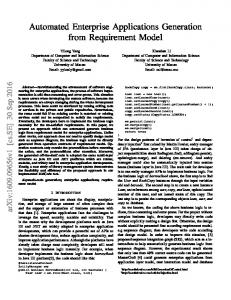
The variability information embedded in use case scenarios can get overloaded and complicated as scenarios contain more and more information. The OVM model collects variability information separately from various artifacts and allows us to manage them effectively. Our approach maps use case scenarios to the OVM, rather than embedding all the variability information in use case scenarios. The approach of Bertlino et al. [5] is complicated by adding several types of tags, such as alternative, parametric, and optional, to the use case scenario. Our idea is to adopt the OVM model to manage variability so that tags become much simpler than before. To make tagged use case scenarios, the inputs in this step are the OVM and the textual description of functional requirements. One of the inputs, the OVM model, needs to be transformed to textual formal description that can be understood by the system. Next, variation points to be mapped to the OVM in the text-based functional requirements should be found. Actually, identifying variabilities from text-based functional requirements involves human intervention. Therefore it is not easy to apply formal methods to variability identification. We suggest the following empirical technique. Figure 1 shows part of textual description of a system that appears in the paper [6]. Because the oven is to be sold around the world, it must be able to vary the display language. The default language is English, but other possible languages are French, Spanish, German, and Italian. The basic oven has a one-line display; more-advanced ovens can have multi-line displays.
Figure 1. System description example
To generate product use case scenarios, valid sets of variants must be selected. This process is performed by ‘Set-Based Selection’. With selected sets, product use case scenarios can be generated.
[Language]
3.1. Basic Concepts for Set-Based Selection
[Display]
Our approach is based on two main concepts. The first one is the tagged use case scenarios, which is described in Section 3.1.1. The second one is the Setbased Variability Expression described in Section 3.1.2. The automated selection algorithm and the product use case scenario generation method will be presented in Section 4 based on the two concepts
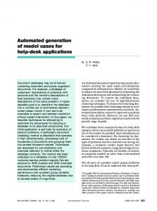
Language1: English Language2: French Language3: Spanish Langauge4: German Language5: Italian Display1: a one-line display Display2: multi-line displays
Figure 2. Two variability examples extracted from requirements specification of Figure 1 On the basis of the variability information in Figure 1, VPs in the common scenario are expressed as in Figure 2. According to Figure 2, the microwave oven displays messages in a variant language of the VP
761 Authorized licensed use limited to: Korea Advanced Institute of Science and Technology. Downloaded on May 12,2010 at 00:48:21 UTC from IEEE Xplore. Restrictions apply.
represented as follows:
[Language]. The display type of microwave oven is indicated through the [Display] VP. In contrast to [4], these tags are used only for marking VPs in use case scenarios of product line. In our approach, we just adopt the basic tag notation from [4] for that purpose. In our usage of tags, it has some variability information and is mapped to the VPs or variants of the OVM model. For this reason, it is not necessary to have all kinds of tags. Furthermore, a complicated logical expression to check conformance as used by Bertilino et al. [5] is not necessary because in our approach the OVM model has all the variability information.
% [1..2] VP = {{v1},{v2},{v3},{v1,v2},{v1,v3},{v2,v3}}
Since this dependency is related to the relationship between VPs or between VP and variant, they do not affect the representation of variability directly. However, this information is critical when a Set-based Variability Expression (SVE) is expanded, which will be explained in Section 3.2. We consider six kinds of constraint dependencies: ‘variant requires variant’, ‘VP requires VP’, ‘variant requires VP’, ‘variant excludes variant’, ‘VP excludes VP’, ‘variant excludes VP’. The constraint relation represents these six kinds of constraint dependencies in the form of a relation. Source and Target are sets of variants which are, respectively, sources and targets of the dependency. Furthermore, in order to represent those constraints with other variants, the ‘!’ operator for excludes is defined. With the standard definitions of dom, we define ‘ !’ operator for exclusion as follows:
3.1.2. Set-Based Variability Expression To handle VPs and variants with an algorithmic way, variability information of the OVM model need be abstracted. Jaring et al. [10] proposed taxonomy of variability dependencies based on a set representation. Mannion [11] showed how to represent features using logic expressions but it is not optimized for the OVM model and did not provide any automated approach. By using Z notation [12], we can represent VPs and variants in a more formal way. OVM contains several notations for representing dependencies between variabilities. When representing VPs and variants with a set-based expression of Z, dependency types must be considered. There are three kinds of dependencies: variability dependency, artifact dependency and constraint dependency. Figure 3 shows an OVM model that has alternative choices. In Figure 3, ‘[1..2]’ means that at least one but no more than two variants need be selected.
o[X]pppppppppppppppppppp c_ !_: %X J (X ({Scenario A,B} , {tag=tag0.2, tag1=tag1.1}) {a2,b2} => ({Scenario A,B,C} , {tag0=tag0.2, tag1=tag1.2}) {a2,b1,b2} => ({Scenario A,B,C}, {tag0=tag0.2, tag1=tag1.1 | tag1=tag1.2})
[vp:core] [v:ws:mandatory] [v:he:mandatory] [v:pl:optional] [v:mp:optional] [vp:wst] [v:analog:alternative0] 1-1 [v:boolean:alternative0] 1-1 [vp:het] [v:one-lh:alternative0] 1-1 [v:multi-lh:alternative0] 1-1 [vp:plt] [v:alternative0:one-lp] 1-1 [v:alternative0:multi-lp] 1-1 [requires] [v:ws] - [vp:wst] [v:he] - [vp:het] [v:pl] - [vp:plt] [excludes][v:multi-lp] - [v:one-lh] [v:analog] - [v:mp]
We represent generated product use case scenarios as X => (a set of scenarios, a set of tags). For example, Scenario A => {(tag0.1)}, means that if a variant ‘a1’ is selected, ‘Scenario A’ is generated by replacing a VP tag ‘tag0’ with the contents of tag0.1.
Figure 8. Textual OVM Figure 9 describes the product line use case scenario mapped to the OVM in Figure 7. For space limitation, some VPs were omitted. The textual use case includes four kinds of tags. Each tag is expanded in the variation section in the use case scenario.
Figure 6. Use case model for the case study [6] Based on the use case model and system requirements in [6], the OVM can be also created as in Figure 7, which can be transformed to the textual representation in Figure 8.
Use case name: Cook Food. ... Description: 1. User opens the door, puts food in the oven, and closes the door. Cooking is prohibited if [WST] detects no items in the oven. 2. User selects power level within [PLT]. {User presses the Cooking Time button following [MP] procedure.} 3. System prompts for cooking time. 4. User enters the cooking time on the numeric keypad and presses Start. ... Variations: [WST] WST1: Analog Sensor WST2: Digital Sensor [PLT] PLT1: One-level PLT2: Multi-level [MP] If selected, then it results in one minute being added to the cooking time. If the cooking time was previously zero, cooking is started. [HET] HET1: One-level HET2: Multi-level
Figure 9. A tagged use case Figure 7. OVM for Cook Food use case
764 Authorized licensed use limited to: Korea Advanced Institute of Science and Technology. Downloaded on May 12,2010 at 00:48:21 UTC from IEEE Xplore. Restrictions apply.
automated. By using a selection algorithm and mapping tags in use case scenarios to the OVM model, generating product use case scenarios becomes very simple and fast because we just choose the appropriate scenario sets for a specific product. Second, the proposed approach helps product use case scenarios represent all the information on variability including the hidden dependencies among scenarios. Because tags in the tagged use case scenario are mapped to the OVM, the tags can be combined with all possible variability sets . Dependency of variants can raise new dependencies among use case scenarios. These hidden dependencies can be caught as early as possible by starting the use case selection with the OVM because the OVM gives the full information on variability dependency.
Based on the tagged use case and the OVM, the initial SVE can be obtained as follows: %* Core = % [2..2] {WS,HE}J%{PL,MP} = {{WS,HE},{WS,HE,PL},{WS,HE,MP},{WS,HE,PL,MP}}
and the relations for PL constraints are represented as: Source = = {WS, HE, PL, Multi-LP, Analog}. Target = = {WST, HET, PLT, One-LH, MP}. requires = { WSU WST, HEU HET, PLU PLT} excludes = { Multi-LPU One-LH, AnalogU MP} The initial SVE is expanded with requires. So {{WS,HE},{WS,HE,PL},{WS,HE,MP},{WS,HE,PL,MP }} $ requires ={{WS,HE}J%[1..1]WSTJ% [1..1]HET,{WS,HE,PL}J% [1..1]WSTJ% [1..1]HETJ% [1..1]PLT,{WS,HE,MP}J% [1..1]WSTJ% [1..1]HET,{WS,HE,PL,MP}J% [1..1]WSTJ% [1..1]HETJ% [1..1]PLT }
After the above process is repeated, 15 sets of variants are finally obtained. Since the variants in SVE were already mapped to tags in the tagged use case scenario, product use case scenario can be automatically generated by replacing variant names with actual tags. For example, the set
References [1] John, I., Muthig, D., "Modeling Variability With Use Cases", Fraunhofer IESE-Report, 063.02/E, Nov. 2002. [2] John, I., Muthig, D., "Product Line Modeling with Generic Use Cases," Proc. Workshop on Techniques for Exploiting Commonality Through Variability Management, 2nd Software Product Line Conf., 2002. [3] Trigaux, J.C., Heymans, P. "Modeling variability requirements in Software Product Lines: A comparative survey," Technical report PLENTY project, Institut d’Informatique FUNDP, Nov. 2003. [4] Bertolino, A., Fantechi, A., Gnesi, S., Lami, G., “Product Line Use Cases: Scenario-Based Specification and Testing of Requirements,” Ch. 11 of Software Product Lines: Research Issues in Engineering and Management, (Eds.) T. Käkölä and J. C. Duenas, Springer, 2006. [5] Bertolino, A., Mantechi, A., Gnesi, S., Lamir, G., Maccari, A., “Use Case Description of Requirements for Product Lines,” Proc. Workshop on Requirements Engineering for Product Lines, 2002. [6] Gomaa, H., Designing Software Product Lines with UML: From Use Cases to Pattern-Based Software Architectures, Addison Wesley, July 2007. [7] Nebut, C., Pickin, S., Le Traon, Y., Jezequel, J.M., "Automated requirements-based generation of test cases for product families," Proc. 18th IEEE Int’l Conference on Automated Software Engineering,, 2003. [8] Biddle, R., Noble, J., Tempero, E., “Supporting Reusable Use Cases, Software Reuse: Methods, Techniques, and Tools,” Proc. 7th Int’l Conf on Software Reuse: Methods, Techniques, and Tools, Springer, LNCS 2319, 2002. [9] Pohl, K., Böckle G., Frank van der Linden. Software Product Line Engineering, Springer, 2005 [10] Jaring, M., Bosch, J. "Variability Dependencies in Product Family Engineering," 5th Workshop on Product Family Engineering, Springer, 2003. [11] Mannion, M., "Using first-order logic for product line model validation," Proc. 2nd Int’l Conf. on Software Product Lines, Springer, 2002. [12] Woodcock, J., Davies J., Using Z Specification, Refinement, and Proof, Prentice Hall Europe, 1996.
{WS,HE,PL,One-LP,Analog,One-LH}
can be represented as actual tags instantiated by 'PLT=PLT1,WST=WST1,HET=HET1'.
The product use case scenario finally derived from this instantiated tags is shown in Figure 10. Use case name: Cook Food. ... Description: 1. User opens the door, puts food in the oven, and closes the door. Cooking is prohibited if [Analog Sensor] detects no items in the oven. 2. User selects power level within [One-level]. 3. System prompts for cooking time. 4. User enters the cooking time on the numeric keypad and presses Start. 5. System shows {[one-level] selection} screen. System starts cooking the food. ...
Figure 10. Product use case scenario
5. Conclusion and Future Works In order to support generating product use case scenarios, we proposed a systematic procedure of automated generation of use case scenarios for product lines. Our approach provided (1) the mapping mechanism with simplified tagged use case scenarios for product lines, (2) automated selection of valid sets of variants, and (3) automated generation of product use case scenarios. Our approach has made two contributions to product use case scenarios derivation: First, this approach makes a product use case selection
765 Authorized licensed use limited to: Korea Advanced Institute of Science and Technology. Downloaded on May 12,2010 at 00:48:21 UTC from IEEE Xplore. Restrictions apply.