Journal of Visualized Experiments
www.jove.com
Video Article
Automated, High-resolution Mobile Collection System for the Nitrogen Isotopic Analysis of NOx 1,2
2,3
1
2,3
Paul K. Wojtal , David J. Miller , Mary O'Conner , Sydney C. Clark , Meredith G. Hastings
2,3
1
Department of Chemistry, Brown University
2
Institute at Brown for Environment and Society, Brown University
3
Department of Earth, Environmental, and Planetary Sciences, Brown University
Correspondence to: Meredith G. Hastings at
[email protected] URL: http://www.jove.com/video/54962 DOI: doi:10.3791/54962 Keywords: Environmental Sciences, Issue 118, nitrogen oxides, isotopes, atmospheric chemistry, vehicles, air quality, mobile Date Published: 12/20/2016 Citation: Wojtal, P.K., Miller, D.J., O'Conner, M., Clark, S.C., Hastings, M.G. Automated, High-resolution Mobile Collection System for the Nitrogen Isotopic Analysis of NOx. J. Vis. Exp. (118), e54962, doi:10.3791/54962 (2016).
Abstract Nitrogen oxides (NOx = NO + NO2) are a family of atmospheric trace gases that have great impact on the environment. NOx concentrations directly influence the oxidizing capacity of the atmosphere through interactions with ozone and hydroxyl radicals. The main sink of NOx is the formation and deposition of nitric acid, a component of acid rain and a bioavailable nutrient. NOx is emitted from a mixture of natural and anthropogenic sources, which vary in space and time. The collocation of multiple sources and the short lifetime of NOx make it challenging to quantitatively constrain the influence of different emission sources and their impacts on the environment. Nitrogen isotopes of NOx have been suggested to vary amongst different sources, representing a potentially powerful tool to understand the sources and transport of NOx. However, previous methods of collecting atmospheric NOx integrate over long (week to month) time spans and are not validated for the efficient collection of NOx in relevant, diverse field conditions. We report on a new, highly efficient field-based system that collects atmospheric NOx for isotope analysis at a time resolution between 30 min and 2 hr. This method collects gaseous NOx in solution as nitrate with 100% efficiency under a variety of conditions. Protocols are presented for collecting air in urban settings under both stationary and mobile conditions. We detail the advantages and limitations of the method and demonstrate its application in the field. Data from several deployments are shown to 1) evaluate field-based collection efficiency by comparisons with in situ NOx concentration measurements, 2) test the stability of stored solutions before processing, 3) quantify in situ reproducibility in a variety of urban settings, and 4) demonstrate the range of N isotopes of NOx detected in ambient urban air and on heavily traveled roadways.
Video Link The video component of this article can be found at http://www.jove.com/video/54962/
Introduction 1,2
Atmospheric nitrogen oxides (NOx = NO + NO2) are important species in the global reactive nitrogen cycle . NOx in the atmosphere is highly reactive and directly contributes to the oxidizing capacity of the atmosphere through its interactions with ozone (O3) and hydroxyl radical (OH). NOx is removed from the atmosphere on the scale of hours to days in the lower troposphere via oxidation to nitric acid (HNO3) or nitrate (NO3 ), both of which are highly soluble and can be dry deposited on surfaces in gaseous and particulate aerosol forms or wet deposited by precipitation 2 (e.g., acid rain) . NOx is emitted from a variety of sources, including fossil fuel combustion, biomass burning, microbial processes in soils, and lightning. Source apportionment is crucial for understanding the impacts of individual sources, but the variety of sources, their variability in space and time, and the relatively short lifetimes of NOx and HNO3 make concentration analyses alone an inadequate metric. Stable isotopes may be useful as a way to better track the spatial patterns and temporal trends of sources and the chemistry of NOx and NO3 in the environment and 3 to add new constraints on atmospheric models . To date, the isotopic signatures associated with different NOx sources remain highly uncertain, 4 particularly because of large uncertainties associated with previous methods . Previous studies represent a number of different active and passive collection methods and yield large ranges in reported isotopic values, even for the same emission source. Fibiger et al. found that previously used methods often varied greatly in terms of their efficiency in capturing NOx, 4 with changes in conditions greatly influencing field collection (e.g., temperature, humidity, flow rates, age of solution) . The inefficient uptake 14 15 of previous NO and NO2 capture methods could lead to fractionations. For example, higher rates of oxidation for N relative to N could yield 15 4,17 low biases in δ N-NOx that are not representative of atmospheric values. In addition to methodological issues , a variety of different types of air sampling may also contribute to differences in the reported ranges for isotope values associated with the same source. For example, 5 6 isotopic signatures associated with vehicle emissions of NOx have been suggested based on collections at near-road sites , in traffic tunnels , 7,8 and directly from the tailpipes of vehicles . Furthermore, previous methods have time resolutions of 24 h at best, and significant changes in 9 ambient NOx concentrations are observed on hourly (or shorter) timescales , potentially limiting the application of isotopic detection for different sources. Many of the NOx collection methods require very strong oxidizing solutions capable of oxidizing NOx, but also other collected reactive nitrogen species (e.g., ammonium), to nitrate over time, potentially contributing an isotopic measurement interference. Some previous methods Copyright © 2016 Creative Commons Attribution-NonCommercial-NoDerivs 3.0 Unported License
December 2016 | 118 | e54962 | Page 1 of 13
Journal of Visualized Experiments
www.jove.com
are also limited to collecting NO2 in solution, which provides only a limited understanding of NOx isotopes, as it does not collect NO (the primary emission). Thus, there is a need to capture NOx from different emissions sources using a consistent, validated method to better constrain whether the variability in isotopes of NOx (and NO3 ) in the environment can be used to directly track sources and chemistry. This paper reports on a field-based NOx collection technique for isotopic analysis with the requisite time resolution, collection efficiency (100%), 4 and reproducibility (≤1.5‰) for application in multiple field environments. The method, originally described by Fibiger et al. , is further validated through the demonstration of its collection efficiency under changing NOx and meteorological conditions in the field, the test of solution stability and ammonia interferences, and the substantiation of its reproducibility in urban environments. Spatial and temporal differences in isotopic values are investigated using a single laboratory- and field-verified method that can capture NOx in solution at high efficiency. This paper demonstrates the application of the method for near-road, on-road, and ambient urban air collections at time resolutions of 30 to 120 min. -
In brief, NOx (NO and NO2) is collected from the atmosphere in a highly oxidizing solution as NO3 . At the same time, ambient NOx, NO2, and CO2 concentrations and other relevant data, such as GPS location and time of collection, are recorded. After a sample is collected, the solution is processed in the laboratory, which involves reducing the solution to stop the reaction, then neutralizing the solution pH for subsequent NO3 concentration and isotopic analyses. The NO3 concentration is determined here by an automated spectrophotometric (i.e., colorimetric) process. The nitrogen isotopic composition is determined using the denitrifier method, which quantitatively converts the NO3 in solution to gaseous N2O that is subsequently measured on an isotope ratio mass spectrometer. Laboratory and field blanks are also collected and measured as part of the collections to ensure the sample integrity. Below is a detailed step-by-step protocol.
Protocol
1. Solution Preparation 1. Before sampling, prepare the solutions, calibrate the NOx analyzer (either luminol or chemiluminescence), and check that the system is working properly and that new filters are installed. 10 2. Make sampling solutions using 1 M potassium permanganate (KMnO4) stock solution and 10 M sodium hydroxide (NaOH) , and then dilute the solution with ultrapure water to the correct volume. 4 NOTE: Purchase premade solutions because they tend to contain lower "blank" NO3 concentrations than other forms. 1. Prepare 10 M NaOH. 1. Weigh out 200 g of solid NaOH and pour it into a 500 ml volumetric flask. Add ultrapure water (18.2 MΩ·cm at 25 °C) to the meniscus line of the volumetric flask and allow the NaOH to dissolve. 2. Because this process exudes heat, place the volumetric flask in a room-temperature (~22 °C) water bath and allow it to cool as it dissolves, usually taking 1-2 hr. Store 10 M NaOH in 500 ml amber plastic bottles for up to 1 month. 3. Prepare a sampling solution of 0.25 M KMnO4 and 0.5 M NaOH in a 500 ml graduated cylinder (450 ml solution volume). 1. Add 112.5 ml of 1 M KMnO4 and then fill with ultrapure water up to 405 ml. 2. Add 22.5 ml of the 10 M NaOH solution prepared in step 1.2.1 to the graduated cylinder and fill to the 450 ml line with ultrapure water. 4. Store the solutions in 500 ml amber glass bottles and label each solution with the date (use letters to distinguish each bottle). 5. Once the solution is made, take a laboratory blank. Remove 25 ml of the solution and record from which solution bottle it came. Store blanks in 60 ml amber glass bottles. NOTE: Each solution bottle should yield 8-11 samples (35-50 ml each) and one field blank (25 ml) after the laboratory blank is taken.
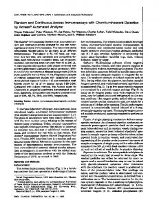
2. Field Setup 1. Choose a sampling location (such as a rooftop) and install the system (if using the stationary system). For the mobile laboratory, pack all instrumentation into a typical passenger vehicle. See Figure 1 for a diagram of the automated system. 2. Change all filters labeled in Figure 1 before sampling to ensure that they are working most effectively and efficiently. NOTE: There are three types of filters in the system: a PTFE particle filter (1.0 µm; 47 or 25 mm use the larger surface area in more polluted air) to remove particles that may contain NO3 , a nylon membrane filter (1.0 µm) for removal of HNO3 gas, and a hydrophobic filter (10.0 µm) to protect the vacuum pump and the critical orifice from solution droplets. With new filters at the start of a sampling period, the particulate filter and the NO3 filter will not need to be changed for a couple of days, except in highly polluted or dusty conditions. The hydrophobic filter should be changed every 4-6 hr for as long as sampling is continuously done. 3. For installation of the system, connect the system and the instruments to polytetrafluoroethylene (PTFE) tubing (1/4-inch outer diameter) and aim the inlet, also PTFE tubing, in the direction of the desired air collection. NOTE: The mobile laboratory is for taking on-road measurements, whereas the stationary laboratory is for taking ambient urban air and nearroad measurements. 4. Set up the 'mobile laboratory', consisting of the NOx collection system, an NOx box, a CO2 analyzer, a global positioning system (GPS) unit, and a marine battery. 1. Pack the system and all instrumentation into the car. Power the system with a 12 V marine deep-cycle battery for ~12 hr, similar to the maximum duration of one day of mobile measurements. Recharge the battery at the end of the sampling day to prepare for the next day. NOTE: Use a separate battery so that there is no need to hardwire to the car battery nor to keep the car running to make measurements. Use two batteries if sampling will be close to or more than 12 hr in order to avoid stopping for a few hours to recharge the battery.
Copyright © 2016 Creative Commons Attribution-NonCommercial-NoDerivs 3.0 Unported License
December 2016 | 118 | e54962 | Page 2 of 13
Journal of Visualized Experiments
www.jove.com
2. Connect the instruments to the PTFE inlet tube closer to the inlet than to the collection system, because the vacuum pump for the system operates at flow rates of 3-5 L/min, much larger than the flow rates for the NOx box (~1.5 L/min) or the CO2/H2O analyzer (30 sec), which is better for ambient air measurements. 1. Calibrate based on the manufacturer's instructions using a gas dilution calibrator. Dilute a standard of 25 ppmv NO in N2 with zero air to achieve approximately seven calibration points between 0-200 ppbv NO. Using an ozone titrator, calibrate the NO2 concentrations across the same range (0-200 ppbv NO2). 11
6. If using the mobile laboratory, calibrate the NOx box-a luminol-based NO2/NO analyzer and a differential, non-dispersive infrared (NDIR) CO2/H2O analyzer using a commercial gas dilution calibrator and following the manufacturer's instructions. The NOx box has a response time of ~5 sec, which is better equipped to resolve on-road NOx emission plumes.
3. Sample Collection 1. Perform tests on the system to ensure that the flow meter, the syringe pump, the computer software, and the vacuum pump are all working. Turn on each component and check that it is working properly. With the computer software, complete the sampling protocol once or twice to make sure that everything is working properly. 2. Turn on the system so that air is bubbling through the solution and bubbles are visible. NOTE: The computer program automates the movement of the solutions throughout the system, but the diaphragm pump and the vacuum pump are operated manually. The user must select the amount of time for the collection of a sample (between 30 and 120 min) that collects enough NOx for the concentration of the sample to be above the blank nitrate concentration of the solution. Atmospheric NOx concentrations of 50-100 ppbv near sources such as vehicles require only a 30 min collection time. For ambient urban NOx concentrations (5-30 ppbv), samples should be collected for up to 120 min. Using the equations provided in steps 6.5 and 6.5.1, the user can back-calculate the collection time to achieve the desired sample concentration in solution. 1. Use a collection system with a syringe pump to automatically move the solution from the reservoirs into the gas-washing bottle and from the gas-washing bottle to the waste. The four electronically actuated valves and the syringe pump are controlled by a computer program specifically written for the collection system, which has four modes: 1) dispense new solution, 2) clean the tubing, 3) collect the sample, and 4) clean the gas-washing bottle, as follows: 2. To automatically dispense new solution, aspirate 35 ml of solution (VS) into the syringe pump from the solution reservoir and dispense it into the gas-washing bottle. The gas-washing bottle frit causes the solution to bubble when the vacuum pump is turned on and the gas sample is introduced. NOTE: Choose a solution volume between 25-35 ml based on the NOx concentrations sampled and the collection times desired. 3. Clean the tubing between the syringe pump and the gas-washing bottle by automatically pulling the residual solution in the tube back into the syringe and depositing it into the waste container. 4. Once the sampling solution is in the gas-washing bottle, manually turn on the pump. When the desired amount of time for sampling has been achieved, manually turn off the pump. 5. After sampling is done, collect the solution by opening the automated valve under the gas-washing bottle to drain the solution into a collection vial and cap via gravity. When the sample is done collecting NOx, collect the solution in a 60 ml amber glass bottle and manually remove the bottle. The program waits ~2 min for the solution to fully drain and then automatically moves on to the next step. 6. Once the sample is done draining, automatically close the valve and clean the gas-washing bottle by aspirating ultrapure water into the syringe pump and dispensing it into the gas-washing bottle via a spray nozzle to clean the sides of the gas-washing bottle. Extract this wastewater from the gas-washing bottle by aspirating it into the syringe pump and discard it into the waste reservoir. Store the frit with 25 ml of nanopure water. Copyright © 2016 Creative Commons Attribution-NonCommercial-NoDerivs 3.0 Unported License
December 2016 | 118 | e54962 | Page 3 of 13
Journal of Visualized Experiments
www.jove.com
7. Repeat steps 3.2.2 to 3.2.6 to dispense the next solution sample. 3. Take field blanks during the collection for each solution bottle (labeled with the letters A-Z before the beginning of collection) that is used by sending 25 ml of solution through the system without turning on the vacuum pump to collect air. Collect the solution immediately after it is put into the system. 4. Record the volumetric flow rate every 5 min using a flow meter during each collection, along with the air temperature (T) and pressure (P) on the flow meter, to derive the standard flow rate. Flow rates of 3-5 L/min are achieved with a diaphragm pump (30 L/min capacity) and a critical orifice to reduce the flow rate. 1. Set the flow rate at the beginning of sampling to measure the flow approximately every 1 sec. After 5-10 sec, change the flow measurement frequency to 5 min. 2. Collect the flow-rate data every 5 min for the duration of the sampling period. NOTE: If the flow rate drops significantly, the sample should be collected for longer than initially expected. Small changes (