Automated Real-Time Control of Fluidic Self-Assembly of Microparticles Massimo Mastrangeli1,2 , Felix Schill1 , Jonas Goldowsky3 , Helmut Knapp3 , Juergen Brugger2 and Alcherio Martinoli1 Abstract— Self-assembly is a key coordination mechanism for large multi-unit systems and a powerful bottom-up technology for micro/nanofabrication. Controlled self-assembly and dynamic reconfiguration of large ensembles of microscopic particles can effectively bridge these domains to build innovative systems. In this perspective, we present SelfSys, a novel platform for the automated control of the fluidic selfassembly of microparticles. SelfSys centers around a waterfilled microfluidic chamber whose agitation modes, induced by a coupled ultrasonic actuator, drive the assembly. Microparticle dynamics is imaged, tracked and analyzed in real-time by an integrated software framework, which in turn algorithmically controls the agitation modes of the microchamber. The closed control loop is fully automated and can direct the stochastic assembly of microparticle clusters of preset dimension. Control issues specific to SelfSys implementation are discussed, and its potential applications presented. The SelfSys platform embodies at microscale the automated self-assembly control paradigm we first demonstrated in an earlier platform.
I. INTRODUCTION Self-assembly (SA) is an autonomous process whereby ordered structures are formed out of the coordinated spatial organization of their components [1]. In SA information to build structures is mostly intrinsic, distributedly encoded in the properties of the agents and in their local interactions with other agents and with the environment. SA is a form of chemistry, and it can be effectively described and modeled using chemical analogies and formalisms [2], [3], [4]. Given proper boundary conditions, it can produce structures and patterns at all physical scales [1]. SA plays a fundamental role in advanced technology, as well. Particularly, in microand nanotechnology it enables the fabrication [5], [6] and packaging [7], [8] of hybrid multifunctional systems in novel, massively parallel and scalable ways. At scales dominated by surface forces and Brownian motion, SA can represent the only way to achieve controlled deposition [9] and organization [10] of nanoparticles. At macroscopic scales, SA is a scalable coordination mechanism for distributed systems of robotic agents. In these systems, redundant local information and interactions enable robots with limited resources to *This work was funded by the SelfSys project within the framework of the Nano-Tera.ch research initiative. 1 Distributed Intelligent Systems and Algorithms Laboratory (DISAL), ´ School of Architecture, Civil and Environmental Engineering, Ecole Polytechnique F´ed´erale de Lausanne (EPFL), Lausanne, Switzerland 2 Microsystems Laboratory (LMIS1), Institute of Microengineering, ´ School of Engineering, Ecole Polytechnique F´ed´erale de Lausanne (EPFL), Lausanne, Switzerland 3 Swiss Center for Electronics and Microtechnology (CSEM), Alpnach, Switzerland
[email protected]
perform non-trivial collective tasks robustly and without centralized supervision [11]. Active agents such as robotic or M/NEMS modules are extensions of passive agents such as particles. Beside having internal states, active agents can program their interactions, i.e. take decisions about them, as opposed to only and necessarily yielding to hard-coded physical interactions, as for instance atoms do. On the other hand, robotic minimalism aims at achieving the same type of performance of distributed robotic systems through lesser sophisticated agents. The scavenging of propulsion from the environment, the minimization of internal logic states and their embodiment into mechanically switchable states [12] are primary instances of this trend. Adopting SA as collective organization mechanism, these tendencies posit a convergence between robotics and micro/nanotechnology toward an extended conception of self-assembling systems across physical scales [2]. Within this perspective we aim to show that, through specific embodiments, a single control approach can direct the SA of passive interactive agents both at macro- and microscales. In a previous work [3] we presented a centimetric platform (Lily) for the controlled SA of water-floating, magneticallylatching modules. The formation of target structures out of non-autonomous passive modules was modeled and bangbang controlled automatically and in real-time by the M3 framework [3]. The work evidenced how the interplay of assembly and disassembly in distributed systems of reversiblybonding agents is functional to efficient SA. Conversely, in microscopic assembling systems the control of position and motion of microagents is normally open-loop and not automated. For instance, Tolley described the directed fluidic assembly of micromachined, mechanically-locking tiles into irreversible multimeric structures [13]. Donald demonstrated the use of a single global control signal to drive microassembly of stress-engineered MEMS robots [14]. A magnetofluidic apparatus for the directed reconfiguration of sets of millimetric, water-floating magnetic modules was developed by Miyashita [15]. By externally switching the magnetic moment of the modules, akin to an internal module state, the ensuing perturbation of the magnetic field prompted a predictable system rearrangement. Here we present SelfSys, a novel platform for controlled fluidic SA of microparticles (Fig. 1). SelfSys is built around a water-filled microfluidic chamber whereby SA is driven by competitive agitation modes induced by a coupled ultrasonic actuator (Sect. II-A). Three-dimensional polymeric microparticles (Sect. II-B) scavenge their motion from the acousto-
Fig. 1: The automated, closed control loop of the SelfSys platform.
(a) Microfluidic chamber
(b) Acousto-fluidic field
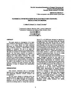
Fig. 2: (a) The SelfSys microchamber, evidencing the air sockets, the access channels and the load (yellow arrow) and unload (blue) flow configurations. (b) CFD simulation of the acousto-fluidic flow field.
fluidic flow field of the microchamber. Their dynamics is imaged, tracked and analyzed in real-time by an integrated software framework (Sect. II-C) which in turn algorithmically switches the agitation modes in the microchamber through the actuator (Sect. II-D). The closed control loop in SelfSys is fully automated, and can direct the stochastic assembly of microparticle clusters of preset dimension (Sect. III). II. EXPERIMENTAL SETUP A. Acousto-Fluidic Microchamber SelfSys centers on a water-filled microfluidic chamber hosting the microparticles SA [16] (Fig. 2a). The 1 cmlong, centro-symmetric chamber is molded in a 400 µm-thick layer of polydimethylsiloxane (PDMS) sealed between two glass slides (Fig. 1a). A motorized pump controls the water flow through three access microchannels, used to respectively input, output and store the microparticles. The flow configuration is set by the state of pneumatic PDMS valves [17] that can be switched to open or close the microchannels. Flow through the lateral (output) microchannel allow the
loading (unloading) of the microparticles in (from) the chamber. The bottom side of the microchamber—which has an acoustic resonance frequency of 40 kHz—is in contact with an ultrasonic piezoelectric actuator with nominal resonance frequency of 60 KHz. A symmetrical array of 20 air-filled, 500 µm-long sockets is patterned along the PDMS sidewalls. The cross-section of the sockets (100 by 100 µm) tunes the resonance frequency of the embedded air bubbles to that of the piezoelectric actuator. The acousto-fluidic actuation of the microchamber is mediated by secondary streaming patterns. The patterns are produced by the oscillation of the water/air interfaces. Thus the symmetrical arrangement of the air bubbles generates a central, laminar flow field (Fig. 2b) dragging the immersed microparticles. Efficient mixing is thus obtained in spite of the chamber’s low Reynolds number (Re, ranging from 12 to 112 according to actuation conditions). By tuning the actuation frequency to the resonance of either the bubbles or the chamber at maximum amplitude, the assembly or disassembly mode of agitation can be respectively incepted. The assembly mode promotes the aggregation and coordination of the microparticles in the center of the chamber. The disassembly mode induces dispersion of the clusters in proximity of the sidewalls. The duality between the microchamber modes is analogous to that embodied in our aforementioned macroscopic Lily platform [3]. Such duality is similarly exploited hereby— i.e. at microscale—to implement a bang-bang control of the stochastic dynamics of the system (Sect. II-D). B. Polymeric Microparticles We fabricated three-dimensional polymeric microparticles as vehicles to investigate the dynamics of fluidic SA in our microchamber [18]. We aimed for microtiles, i.e. passive agents reversibly assembling into planar ordered structures of arbitrary dimension, yet simple enough to be easily batch
interplay makes the assembly of the microtiles reversible. Moreover, upon close packing the chosen geometry enhances the hydrophobic interaction between the microtiles, since the latter is proportional to the contact area and the microtiles can adhere vertically in addiction to laterally. Finally, the microtiles feature a central bichromatic marker—in the form of a pair of steps—to ease their optical tracking, as described in the next Section. C. Particle Tracking (a) Microtile design
(b) Microtiles in water
Fig. 3: (a) 3D design of the microtiles for fluidic SA. (b) Microfabricated SU-8 microtiles in water.
fabricated and tracked during assembly. We referred to the Lily modules for the profile [3] (Fig. 3a), as it enables the self-alignment of the tiles upon coordination into closepacked square lattice. The Lily modules can preserve an imposed vertical orientation while floating at the water/air interface. However, this condition cannot be met in the microchamber. In fact, though the microparticles stand at the chamber’s bottom, they are immersed in bulk water and can move along all spatial degrees of freedom1 . Consequently, the initial vertical orientation of the microparticles cannot be imposed, nor is it likely to be preserved during the assembly process. Given the microtile shape, this would result in the formation of two subpopulations of microtiles with opposite chirality. The subpopulations would not interact tightly because of their unfitting geometry. To face this issue, we designed the microtiles as the superposition of the chiral copies of the original shape (Fig. 3a). Such 3D geometry allows microtiles with either vertical orientation to tightly pack into square lattice patterns. The microtiles (Fig. 3b) were fabricated through the deposition and patterning of two 50 µm-thick layers of SU-8 using thick electroplated copper as sacrificial layer [18]. The SU-8 surfaces are coated with a fluorinated silane-based selfassembled monolayer to increase their hydrophobicity. When in water, hydrophobic surfaces in close proximity interact by short-ranged hydrophobic effects [19]. This interaction and the inter-particle secondary radiation forces produced by the ultrasonic field can be overcome by fluidic drag forces. Such 1 For fabrication and feeding reasons, the height of the microchamber needs to be larger than the width of the microparticles [16].
To track the dynamics of the microtiles, a computer vision solution was implemented coping with the challenges posed by our microfluidic environment. As the microchamber’s bottom side is in direct contact with the piezoelectric actuator, the vision system is limited to reflected-light microscopy. The small depth of field of microscope optics is comparable to the size of the microtiles and the thickness of the microchamber. Thus the microtiles appear blurred as they transiently move out of the focal plane. Though the depth of field can be altered by optical means, the computer vision system needs nonetheless to be robust to blur. The transparency of the microtiles produces low optical contrast, especially when using white omnidirectional lighting. Monochromatic green and unidirectional lighting improved contrast and sharpness as it avoided chromatic aberration and added shadowing underneath the particles. Furthermore, the visibility of the microtiles is mostly due to reflection and refraction of light on their edges. This results in significant changes of appearance dependent on their spatial orientation; besides, lighting conditions can significantly vary when many particles cluster together. Lastly, upon ultrasonic actuation the fast motion of the microtiles (up to 26.6 and 250 mm/s in assembly and disassembly mode, respectively) requires the vision system to capture and process images at frame rates higher than 100 Hz. A high-speed GigE camera (Fastec HighSpec 1) with a microscope lens assembly was mounted above the chamber (Fig. 1b). The camera can capture thousands of frames per second in an internal buffer; yet in real-time streaming mode the capture rate is limited by the bandwidth of the Gigabit Ethernet interface; i.e. for a reduced region of interest of 512 x 512 pixels to 150 frames per second. In summary, our vision tracking system needed to be 1) robust to blur and varying appearance and lighting of particles, 2) able to track multiple objects simultaneously, and ideally 3) able to process images at rates above 100 Hz. Our particle tracking system is represented in Fig. 4. The open source tracking software SwisTrack [20] was extended with new modules for pattern-based particle tracking. An approach based on the cross-correlation of a template pattern against a captured image was chosen and implemented in the Fourier domain. Thus after applying a 2D-FFT, the cameracaptured system image is multiplied with the 2D-FFT of the pattern, i.e. a prepared image of a microtile. To finetune the system to varying blur and lighting conditions, a bandpass filter is applied to the pattern in the Fourier domain at initialisation. Bandpass filtering and pattern matching can therefore be done in a single point-wise multiplication, and
input video
patterns
FFT
FFT
Correlation
filter pattern
inv. FFT
X bandpass
Probabilistic filter
graph clustering
Piezo control
Fig. 4: Diagram of the particle tracking system. The generation of the filter pattern is run only once, thus it does not contribute to the total processing time during operation.
allows to reduce global lighting variations (low frequencies) as well as image noise and specular reflections (high frequencies). After an inverse FFT, the resulting cross-correlation amplitudes can be searched for maxima, which correspond to the best matches of the input pattern. To improve the tracking performance, a Bayesian filter is applied which combines a Gaussian probability distribution of previous matches with the current observation to obtain a new estimate. The filter utilises elements from Monte-Carlo methods to track multiple particles (randomised generation of hypotheses) and histogram methods by representing hypotheses as gaussianblurred points in the image domain. This allows the use of optimised, efficient whole-image operations from the OpenCV library. Steps of the algorithm are shown in Fig. 5. The pattern matching and tracking algorithm was implemented within SwisTrack using the OpenCV library. On an Intel i7 CPU a frame processing rate of 45 Hz was achieved. To further improve the speed, the FFT and multiplication operations were ported to a GPU, using CUDA and OpenCV. As the FFT and pointwise multiplication lend themselves to parallel processing, significant speed-up was possible. Running on a system with a GeForce Titan GPU, the processing time of the whole pipeline per image was less than 5 ms— fast enough to run the tracking system including image capture at the maximum camera capture rate of 150 Hz. The measured execution times for each module are shown in the following table (the Pattern Tracker module combines correlation, inverse FFT and filtering): Speed CPU/GPU FFT Pattern tracker Graph clustering
512x512 4.9 ms / 1.3 ms 8.1 ms / 2.9 ms 0.05 ms
720x720 12.2ms / 2.6 ms 19.2 ms / 5.3 ms 0.05 ms
D. Control Algorithm In this study, we aimed at directing the stochastic assembly of clusters of microtiles with user-defined size. The tracking algorithm provides the instantaneous position of the particles
Algorithm 1 Tracking and control algorithm. It : input image, IT : pattern template of microtiles, Fbp (fc , σ, gain): 2D bandpass filter, Pt : set of points representing tracked tiles. Parameters: β: balance between previous prediction and current matching step, s: radius of microtiles in pixels, θ: matching threshold, γ: desired cluster size. Require: T := FFT(IT - Blur(IT , r=15)) * Fbp (fc , σ, gain) for It : do Iˆt := F F T (It ) ˆ t := Iˆt · T M ˆ t )| Mt := |F F T −1 (M Rt := Blur( {[p.x][p.y]:=1.0} for p in Pt−1 , r=15) Mt0 := ((1.0 − β)Mt + β) · RT Pt ← Pt−1 + 50 randomly distributed points for p in Pt do p := argmax(q in Mt0 | |p − q| < 2s ) if Mt0 (p) < θ then delete(p) end if end for for p, q in Pt | |p − q| < 2s do if Mt0 (p) < Mt0 (q) then delete(p) else delete (q) end if end for Gt := Graph (V = Pt , E = (p, q) in Pt | |p − q| < √s2 ) ct :=LargestClusterSize(Gt ) if ct < γ then set piezo to assembly mode else if ct = γ then switch piezo off else if ct > γ : then set piezo to disassembly mode end if end for
in the field of view of the camera. This information is used to automatically select the actuation mode required to promote the formation of the target structure in the shortest time. A graph G(V, E) is constructed from the output of the microparticle tracker. Each microparticle tracked within a central, user-defined circular area defines a vertex V of G. An edge E is inserted in G for each connected pair of microtiles, i.e. closer than a preset range derived from the microtile size s. A breadth-first clustering algorithm is applied to the adjacency matrix of G to determine the size of its largest connected cluster ct . A control strategy is implemented based on the comparison between ct and the desired cluster size γ. If ct has lower or larger value than γ, the piezoelectric actuator is set to excite the assembly or disassembly mode of the microchamber, respectively. In presence of at least one cluster of the desired size (i.e., for ct = γ), the actuation is arrested—and the microtiles stop their motion almost istantaneously given the low Re of the
Fig. 5: Image processing steps. a) captured input image, b) bandpass-filtered cross correlation (Fourier domain), c) matching result after inverse Fourier transform and probabilistic filtering, d) final tracking displayed on input image.
microchamber (Sect. II-A). The rationale for such bang-bang control law is discussed in the following section. III. RESULTS AND DISCUSSION The combination of the tracking and decision components described above results in Algorithm 1 able to close the control loop of the SelfSys platform. The fully automatic evolution of the system of microparticles from a sparse initial state to one with connected clusters of desired size is thus enabled. Evidence from numerous realizations of the assembly process support the validity of our control approach. It can successfully direct in real-time the formation of target structures in spite of the fast and highly stochastic dynamics of the microtiles in the acousto-fluidic field. Fig. 6 and 7 show excerpts from two different assembly realizations. The driving circuitry of the actuator has negligible latency, and the high sampling rate of the control software allows for system’s response times much shorter than human reaction times. Reaction of microtiles to switches in actuation modes are not istantaneous. They follow from the relatively slow reconfiguration of the flow field. The reconfiguration of the microtiles upon mode swtiching is not predictable, because it can be accompanied by subtle rearrangements of the air bubbles which in turn affect the instantaneous flow field and thus the microtile dynamics. Fine parameter tuning makes the optical real-time tracking of the microparticles robust against accidental light reflections, microtile misorientations and shadows. Occasional glitches appear, particularly in presence of crowding at the center of the microchamber. Peculiarities of the microchamber and of the vision system—particularly, the sticky sidewalls, the erratic motion of the tiles combined with the limited field of view of the
optics—make the gathering of statistically significant data on system performance challenging. The PDMS sidewalls of the microchamber need to be hydrophobic to localize the air bubbles within the sockets. Yet, the ultrasonic field induces mild cavitation in the chamber, which tends to accumulate tinier air bubbles along the sidewalls, as well. As a consequence, when immersed in the water of the microchamber the hydrophobic microtiles tend to stick to the sidewalls by the same hydrophobic interaction that bonds them together when clustered. The microtiles can be detached from the sidewalls by the strong secondary streaming flows originating from the air bubbles in assembly mode. Upon such actuation, the microtiles tend to leave the periphery of the microchamber to aggregate at its center. As a corollary, all assembly realizations start with the assembly mode. Conversely, the disassembly mode scatters the microtiles away from the center toward the sidewalls, dispersing the undesired aggregates but also inducing the eventual adhesion of the microtiles to the sidewalls. Since the sidewalls are outside the field of view of the camera—as mentioned in Sect. II-C—sidewallstuck microtiles cannot be tracked by the dedicated software. As microtiles can enter and exit the field of view, the number of tracked microtiles is generally not constant in time. This makes the system only partially observable—in contrast to its macroscopic counterpart [3]. The time-varying population size makes 1) the accumulation of statistics on the performance of the system harder, and 2) the dynamics of the system not respecting conservation laws in terms of number of units in the system. As a consequence, control strategies based on, for instance, the computation of the reaction rates of the assembling system and expectation/maximization algorithms [3] were not hereby applicable. This motivated the bang-bang control strategy adopted (Sect. II-D) which, being independent on the number of microtiles active in the field of view, overcomes the partial observability issue. IV. CONCLUSION AND FUTURE WORK SelfSys is a novel platform for automatic, real-time closedloop control of self-assembling systems of microparticles. In its ultrasonically-actuated microfluidic chamber the stochastic reconfiguration of the assembling units follows from directed changes of the boundary conditions in the form of global flow fields. A bang-bang control law was shown to direct the formation of target clusters of microparticles from initially sparse states and out of noisy dynamics. An enhanced control strategy accounting for the topology of the target structures is currently being developed. SelfSys enables contactless manipulation and automatic SA of sophisticated functional micro/nanosystems, particularly liquidfilled MEMS capsules [21], [22] embedding transducers [23]. ACKNOWLEDGMENTS The authors thank the SelfSys team and the Center of Micronanotechnology (CMI) of EPFL for constant support. R EFERENCES [1] G. M. Whitesides and B. Grzybowski, “Self-assembly at all scales,” Science, vol. 295, pp. 2418–2421, 2002.
(a) 2.00 s, assembly mode
(b) 2.80 s, disassembly mode
(c) 3.92 s, target structure achieved
Fig. 6: Self-assembly sequence for a small microtile set. Dimension of target cluster: 3.
(a) 7.04 s, assembly mode
(b) 7.24 s, disassembly mode
(c) 7.68 s, target structure achieved
Fig. 7: Self-assembly sequence for a large microtile set. Dimension of target cluster: 5.
[2] M. Mastrangeli, G. Mermoud, and A. Martinoli, “Modeling selfassembly across scales: The unifying perspective of smart minimal particles,” Micromachines, vol. 2, pp. 82–115, 2011. [3] G. Mermoud, M. Mastrangeli, U. Upadhyay, and A. Martinoli, “Realtime automated modeling and control of self-assembling systems,” in IEEE Int. Conf. Robotics and Automation (ICRA), 2012, pp. 4266– 4273. [4] G. Mermoud, Stochastic Reactive Distributed Robotic Systems: Design, Modeling and Optimization, ser. Springer Tracts in Advanced Robotics. Springer, 2014. [5] T. G. Leong., A. M. Zarafshar, and D. H. Gracias, “Three-dimensional fabrication at small size scales,” Small, vol. 6, pp. 792–806, 2010. [6] M. Mastrangeli, S. Abbasi, C. Varel, C. van Hoof, J.-P. Celis, and K. F. B¨ohringer, “Self-assembly from milli- to nanoscales: methods and applications,” J. Micromech. Microeng., vol. 19, pp. 083 001– 083 037, 2009. [7] R. J. Knuesel and H. O. Jacobs, “Self-assembly of microscopic chiplets at a liquidliquidsolid interface forming a flexible segmented monocrystalline solar cell,” Proc. Natl. Acad. Sci., vol. 107, pp. 993– 998, 2010. [8] W. Zheng and H. O. Jacobs, “Fabrication of multicomponent microsystems by directed three-dimensional self-assembly,” Adv. Funct. Mater., vol. 15, pp. 732–738, 2005. [9] T. Kraus, L. Malaquin, H. Schmid, W. Riess, N. D. Spencer, and W. H., “Nanoparticle printing with single-particle resolution,” Nature Nanotech., vol. 2, pp. 570–576, 2007. [10] M. Grzelczak, J. Vermant, E. M. Furst, and L. M. Liz-Marz´an, “Directed self-assembly of nanoparticles,” ACS Nano, vol. 4, pp. 3591– 3605, 2010. [11] G. Mermoud, A. Prorok, L. Matthey, C. M. Cianci, N. Correll, and A. Martinoli, Handbook of collective robotics: Fundamentals and challenges. Pan Stanford Publishing, 2012, ch. Self-Organized Robotic Systems: Large-Scale Experiments in Aggregation and SelfAssembly using Miniature Robots. [12] K. Saitou, “Conformational switching in self-assembling mechanical systems,” IEEE Trans. Robot. Autom., vol. 15, pp. 510–520, 1999. [13] M. T. Tolley, M. Krishnan, D. Erickson, and H. Lipson, “Dynamically
[14] [15] [16]
[17] [18] [19] [20]
[21]
[22]
[23]
programmable fluidic assembly,” Appl. Phys. Lett., vol. 93, p. 254105, 2008. B. R. Donald, C. Levey, I. Papronty, and D. Rus, “Planning and Control for Microassembly of Structures Composed of Stress-Engineered MEMS Microrobots,” Int. J. Robot. Res., vol. 32, pp. 218–246, 2013. S. Miyashita, E. Diller, and M. Sitti, “Two-dimensional magnetic micro-module reconfigurations based on inter-modular interactions,” Int. J. Robot. Res., vol. 32, pp. 591–613, 2013. J. Goldowsky, M. Mastrangeli, L. Jacot-Descombes, M. R. Gullo, G. Mermoud, J. Brugger, A. Martinoli, B. J. Nelson, and H. Knapp, “Acousto-fluidic system assisting in-liquid self-assembly of microcomponents,” J. Micromech. Microeng., vol. 23, p. 125026, 2013. J. Goldowsky and H. Knapp, “Gas penetration through pneumatically driven PDMS micro valves,” RCS Adv., vol. 3, pp. 17 968 – 17 976, 2013. M. Mastrangeli, A. Martinoli, and J. Brugger, “Three-dimensional SU8 microtiles for fluidic self-assembly,” in 39th Int. Conf. on Micro & Nano Engineering (MNE), London (UK), 2013. E. E. Meyer, K. J. Rosenberg, and J. Israelachvili, “Recent progress in understanding hydrophobic interactions,” Proc. Natl. Acad. Sci., vol. 103, pp. 15 739–15 746, 2006. T. Lochmatter, P. Roduit, C. Cianci, N. Correll, J. Jacot, and A. Martinoli, “SwisTrack - a flexible open source tracking software for multiagent systems,” in 2008 IEEE/RSJ Int. Conf. on Intelligent Robots and Systems (IROS), 2008, pp. 4004–4010. L. Jacot-Descombes, C. Martin-Olmos, M. R. Gullo, V. J. Cadarso, G. Mermoud, L. G. Villanueva, M. Mastrangeli, A. Martinoli, and J. Brugger, “Fluid-mediated parallel self-assembly of polymeric microcapsules for liquid encapsulation and release,” Soft Matter, vol. 9, pp. 9931–9938, 2013. M. Mastrangeli, L. Jacot-Descombes, M. R. Gullo, and J. Brugger, “Liquid-filled sealed MEMS capsules fabricated by fluidic selfassembly,” in IEEE Int. Conf. on Micro Electro Mechanical Systems (MEMS), 2014, pp. 56–59. L. Jacot-Descombes, M. R. Gullo, M. Mastrangeli, V. J. Cadarso, and J. Brugger, “Inkjet printed SU-8 hemispherical microcapsules and silicon chip embedding,” Micro & Nano Letters, vol. 8, pp. 633–636, 2013.