REVIEW OF SCIENTIFIC INSTRUMENTS
VOLUME 74, NUMBER 12
DECEMBER 2003
Automated spectro-goniometer: A spherical robot for the field measurement of the directional reflectance of snow Thomas H. Paintera) Institute for Computational Earth System Science, University of California, Santa Barbara, California 93106
Brad Paden Department of Mechanical and Environmental Engineering, University of California, Santa Barbara, California 93106
Jeff Dozier Donald Bren School of Environmental Science and Management, University of California, Santa Barbara, California 93106
共Received 3 April 2003; accepted 21 September 2003兲 We describe an automated spectro-goniometer 共ASG兲 that rapidly measures the spectral hemispherical-directional reflectance factor 共HDRF兲 of snow in the field across the wavelength range 0.4⭐⭐2.5 m. Few measurements of snow’s HDRF exist in the literature, in part caused by a lack of a portable instrument capable of rapid, repeatable sampling. The ASG is a two-link spherical robot coupled to a field spectroradiometer. The ASG is the first revolute joint and first automated field goniometer for use over snow and other smooth surfaces. It is light enough 共⬃50 kg兲 to be portable in a sled by an individual. The ASG samples the HDRF at arbitrary angular resolution and 0.5 Hz sampling rate. The arm attaches to the fixed-point frame 0.65 m above the surface. With vertical and oblique axes, the ASG places the sensor of the field spectroradiometer at any point on the hemisphere above a snow target. In standard usage, the ASG has the sun as the illumination source to facilitate in situ measurements over fragile surfaces not easily transported to the laboratory and to facilitate simultaneous illumination conditions for validation and calibration of satellite retrievals. The kinematics of the ASG is derived using Rodrigues’ formula applied to the 2 degree-of-freedom arm. We describe the inverse kinematics for the ASG and solve the inverse problem from a given view angle to the necessary rotation about each axis. Its two-dimensional hemispheric sampling space facilitates the measurement of spectral reflectance from snow and other relatively smooth surfaces into any direction. The measurements will be used to validate radiative transfer model results of directional reflectance and to validate/calibrate directional satellite measurements of reflectance from these smooth surfaces. © 2003 American Institute of Physics. 关DOI: 10.1063/1.1626011兴
I. INTRODUCTION
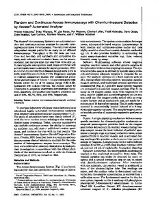
The assumption of isotropic reflectance will frequently produce errors in quantitative retrievals of snow physical properties.3,4 Recent increases in computational power and data storage have enabled scientists to develop and refine quantitative retrievals of snow properties by incorporating the anisotropic reflectance distribution of snow. Existing models for the HDRF of snow2,5,6 have not been compared with a comprehensive sampling of the HDRF and its dependence on solar geometry, wavelength, grain size distribution, grain morphology, liquid water content, and impurities. To meet this need, we have developed an automated spherical robot for use with a high spectral resolution field spectroradiometer 共Fig. 1兲. We describe the automated spectro-goniometer 共ASG兲 in terms of its constraints, spectral range and resolution, kinematics, sampling protocols, and specifications. The ASG is unique in that it is the first revolute joint goniometer and the first automated field goniometer for snow measurements. It is light enough 共⬃50 kg兲 to be portable by an individual via sled. In this section, we define the hemispherical-directional
Distributed snowmelt models use snow-covered area, grain size, albedo, and snow water equivalent for input and validation. Estimates of all but snow water equivalent are available from optical 共solar兲 remote sensing. Algorithms for retrieving these snow properties have been based on the simplifying assumption that snow reflects solar radiation isotropically. We know that snow has an anisotropic reflectance distribution that depends on wavelength, grain size, and grain morphology,1,2 but our understanding is hampered by the lack of measurements that cover the full spectral and angular distribution. Satellites sample only a part of this spectral hemispherical-directional reflectance factor 共HDRF兲 that has been convolved with interactions on heterogeneous terrain. a兲
Author to whom correspondence should be addressed. Now at the National Snow and Ice Data Center, 449 UCB, University of Colorado, Boulder, CO 80309-0449; electronic mail:
[email protected]
0034-6748/2003/74(12)/5179/10/$20.00
5179
© 2003 American Institute of Physics
Downloaded 17 May 2004 to 128.111.111.217. Redistribution subject to AIP license or copyright, see http://rsi.aip.org/rsi/copyright.jsp
5180
Rev. Sci. Instrum., Vol. 74, No. 12, December 2003
Painter, Paden, and Dozier
FIG. 1. Automated spectro-goniometer on snow, Mammoth Lakes, Sierra Nevada, CA.
reflectance factor 共HDRF兲 and the hemispherical-directional reflectance distribution function 共HDRDF兲, review previous measurements of snow HDRF, and review other available goniometers for field measurements of angular reflectance. In Sec. II, we present system constraints and the spectrometer specifications. Section III describes the kinematics of the automated spectro-goniometer and their closed-form inversion. In Sec. IV, we describe the motion control configuration. In Sec. V, we describe the angular calibration of the ASG. Section VI presents the calculation of HDRF from the ASG. Preliminary results and discussion are given in Sec. VII. A. Hemispherical-directional reflectance factor
The commonly used, dimensionless form of the angular distribution of reflectance is the hemispherical-directional reflectance factor 共HDRF兲7,8 HDRF 共 0 , 0 ; r , r 兲 ⫽
⫽
冉
L 共 r , r 兲 0 E dir共 0 , 0 兲 ⫹E diff共 2 兲
L 共 r , r 兲 , 0 E dir共 0 , 0 兲 ⫹E diff共 2 兲
冊 共1兲
where L is spectral radiance 共W m2 sr⫺1 m⫺1兲, E dir is spectral irradiance 共W m⫺2 m⫺1兲 onto a plane normal to the beam of the Sun, E diff is diffuse spectral irradiance 共W m⫺2 m⫺1兲 from the overlying hemisphere 共solid angle of 2 steradians兲 less the solid angle containing the solar disk, 0 is the zenith angle of direct beam irradiance, 0 is the azimuth angle of direct beam irradiance, r is the zenith angle of reflected radiance, r is the azimuth angle of reflected radiance, and 0 is the cosine of 0 . The HDRF is the ratio of radiance reflected into the direction r , r to the radiance that would be reflected into any direction by a perfectly reflecting Lambertian 共i.e., isotropically reflecting兲 surface for the given direct and diffuse irradiance. The hemispherical-directional reflectance distribution function 共HDRDF兲 of a surface describes the magnitude of reflected radiance into a direction relative to the irradiance from a given direction plus the hemispherical diffuse irradiance 共Fig. 2兲
FIG. 2. Representation of hemispherical-directional reflectance.
HDRDF 共 0 , 0 ; r , r 兲 ⫽
HDRF共 0 , 0 ; r , r 兲 .
共2兲
The HDRDF has units of inverse steradians 共sr⫺1兲 and is analogous to the bidirectional reflectance distribution function.7 B. Previous snow HDRF measurements
The literature describing the HDRF of snow is sparse. Previous efforts to characterize the HDRF of snow have been limited with respect to one or more of angular resolution and range, spectral resolution and spectral range, speed of acquisition, and quantitative documentation of snow properties.9–11 Steffen10 measured the HDRDF of snow for the wavelength range 0.5 m⭐⭐0.6 m for a suite of solar zenith angles and view geometries. Dozier et al.12 addressed deficiencies of previous experiments with greater angular sampling and resolution, greater spectral resolution, and more detailed snow characterization. However, the spectrometer they used was sensitive only to the range 0.4⭐⭐1.0 m, up to the shorter wavelength end of the spectral region in which the reflectance of snow is most sensitive to grain size. Leroux et al.2 compared a model with measurements of snow HDRF accompanied by detailed quantification of grain size distribution and grain morphology, but they reported measurements only for ⫽1.68 m. C. Goniometers
Goniometers are instruments that measure angles. The word ‘‘goniometer’’ is derived from the Greek word ‘‘gonia’’ meaning angle. Remote sensing-specific field goniometers have been developed primarily for the study of the HDRF of vegetative covers. Other fields such as optical properties of materials,13 computer graphics modeling,14 and colorimetry15 use goniophotometers in a variety of configurations. Because the ASG is specifically a field goniometer, we review the field goniometers used in remote sensing applications and refer the reader to more comprehensive works describing goniophotometry in other fields.16 The first goniometric field instrument regularly used for remote sensing and radiative transfer analysis of vegetation
Downloaded 17 May 2004 to 128.111.111.217. Redistribution subject to AIP license or copyright, see http://rsi.aip.org/rsi/copyright.jsp
Rev. Sci. Instrum., Vol. 74, No. 12, December 2003
was the portable apparatus for rapid acquisition of bidirectional observations of the land and atmosphere 共PARABOLA兲.17 The PARABOLA, a dual-axis up-anddown-looking three-band radiometer, rides a tram cableway over a target such as a vegetation canopy. In geometric terms, PARABOLA looks from the center of a hemisphere out to discrete points on the hemisphere. This geometry dictates that PARABOLA views different targets at each pair of zenith and azimuth view angles and so configured, relies on the assumption that the surface cover is spatially homogeneous. The latest version of PARABOLA is the PARABOLA III, described by Bruegge et al.18 The Remote Sensing Laboratories at the University of Zu¨rich developed the field goniometer system 共FIGOS兲 for hyperspectral measurement of the hemispherical-directional reflectance distribution of vegetation and soils.19 FIGOS has a 2 m radius zenith arc with a tram that carries a GER Corporation GER-3700 spectroradiometer, and an azimuth support track. FIGOS can cover the hemisphere at 15° angular sampling in approximately 18 min, making 66 measurements. While the FIGOS weighs 230 kg and requires two technicians for assembly and operation, it has advantages over PARABOLA in that it measures the complete optical spectrum at high spectral resolution and views the same target for all spectra. Aoki et al.20 sampled snow HDRF and albedo with a goniostage coupled to a tripod. This instrument is similar to PARABOLA in that it views the surface from the center of the hemisphere and assumes spatial homogeneity. While this instrument is inexpensive to manufacture and deploy, the occultation of many view zeniths and azimuths by the tripod prevents complete HDRF sampling. Of these goniometric instruments, the PARABOLA and FIGOS are automated. The ASG described here simplifies the mechanism design by employing revolute joints with a relatively inconsequential increase in computational complexity of the kinematics.
Robot for directional reflectance of snow
5181
TABLE I. Specifications for Analytical Spectral Devices FR FieldSpec Spectroradiometer. Parameter
Value
Spectral range Spectral resolution
0.35–2.5 m 0.003 m 共0.35⭐⭐1.0 m兲 0.010 m 共1.0⭐⭐2.5 m兲 10 spectra/s 1 spectrum/s 共max. rate兲 9.2 kg 2.5 m 1°, 4°, 8° 3.7⫻10⫺10 W/cm2/nm/sr @ 700 nma
Spectrum sampling rate Spectrum recording rate Weight Optic cable length Fore optics Noise-equivalent change in reflectance 共NE⌬L兲 a
Provided on the Analytical Spectral Devices webpage www.asdi.com.
GaAs photodiodes to cover the wavelength range 1.0–2.5 m. We show the specifications for the ASD-FR in Table I and the reader may find further specifications at http:// www.asdi.com. Of note here are the complete spectral range 共0.35–2.5 m兲, high spectral resolution 共0.003–0.010 m兲, and the rapid spectrum acquisition 共10 spectra/s and an average spectrum automatically recorded at 1 Hz兲. With the rapid spectrum acquisition, the ASG may access a dense grid of points on the hemisphere above the snow target with little change in solar geometry.
B. Configuration
The ASG has two independently controlled motorized arms serially attached to a boom that extends from a circular base 共Fig. 3兲. The boom has an attachment point for the first motor and the upper joint housing that encloses a radially pre-loaded anti-backlash worm wheel, worm shaft, and ball bearing assembly 共Fig. 4兲. Two ball bearings support the worm wheel. The second motor attaches to the end of the
II. SYSTEM DESCRIPTION
A comprehensive characterization of snow HDRF must address two sets of parameters, one set corresponding to instrumentation and the other corresponding to snow and atmospheric characterization. The instrument parameters are spectral range and resolution, acquisition speed, angular range and resolution, angular accuracy, and acquisition speed 共if using the sun as an illumination source兲. Characterization of the snow and atmosphere includes the spectral ratio of diffuse to direct irradiance, grain size distribution, grain morphology and its distribution, snow liquid water content, density, and impurities. This section discusses the instrumentation. A. Field spectrometer
The automated spectro-goniometer manipulates the sensor of an Analytical Spectral Devices FieldSpec FR spectroradiometer21 共ASD-FR兲. The ASD-FR has a 512 element Si photodiode array to cover the wavelength range 0.35–1.0 m, and two separate TE-cooled, graded index In-
FIG. 3. Geometry for the automated spectro-goniometer. The elbow axis k 0 , lies in the x-z plane, with a zenith angle of ⫽46.5° off of the z axis. The three vectors z 共vertical axis兲, k 0 共the oblique axis兲, and u 共the view vector兲 intersect at the hemisphere origin, 1 and 2 are the rotations about z and k 0 , respectively. The elbow axis k 0 lies in the x-z plane when 1 ⫽0.
Downloaded 17 May 2004 to 128.111.111.217. Redistribution subject to AIP license or copyright, see http://rsi.aip.org/rsi/copyright.jsp
5182
Rev. Sci. Instrum., Vol. 74, No. 12, December 2003
FIG. 4. ASG upper joint assembly. The joint housing and upper motor housing 共right兲 are suspended from the ASG boom. A worm shaft 共threaded兲 extension to the motor shaft drives the anti-backlash worm gear 共center兲. The upper arm extends off to the left from the upper shaft.
Painter, Paden, and Dozier
FIG. 6. ASG fore-optic mount. The mount is threaded to accept Analytical Spectral Devices fore optics 共black cylinder with white band兲.
III. KINEMATICS
first arm in a lower joint housing 共Fig. 5兲. This housing contains the second worm gear, worm shaft, and a single ball bearing. The ASD-FR optic cable end point attaches to the end of the lower arm of the ASG 共Fig. 6兲. The optic cable points at the center of the base circle from the scanning space of the hemisphere above this center 共discussed in Sec. III兲. Brushless servomotors drive rotation about the vertical and oblique axes, placing the optic cable end point at any point on the hemisphere. Hence, the ASG has arbitrary angular range. In design and manufacture, we specified angular accuracy of 2°. The Pittman motor/encoders described below have 2000 counts per revolution which, combined with 72 and 95 teeth worm gears, provide potential angular resolutions of 0.0025° and 0.0019°, although joint flexibility and friction prevent the attainment of these resolutions.
In this section, we present the kinematics of the mechanism. The kinematics of the 2 degree-of-freedom robot describe the view vector, u, as a function of the joint angles 1 and 2 共Fig. 3兲. The fore-optic mount moves in the hemisphere of constant radius 共0.65 m兲 about the target. The kinematics of the ASG are derived using Rodrigues’ formula22 for a spherical displacement of a rigid body. The protocol for use of the ASG is determined by a prescribed set, U, of viewing angles or view vectors u. Hence, we must solve the inverse kinematics problem: given u, find 1 , 2 which are the respective rotations about ⫺z and k 0 . Except at full reach and full retraction of the ASG arms, there are two solutions to the inverse kinematics problem. All joint rotations are about axes that pass through the center, O, of the hemisphere which is coincident with the target. If k is an axis of rotation, the 3⫻3 rotation matrix R k that represents the rotation about k by an angle is given by R k 共 兲 ⫽ 共 1⫺cos 兲 kk T ⫹cos I⫹sin 关 k⫻ 兴 , where 关 k⫻ 兴 ⬅
冋
0
⫺k 3
k3
0
⫺k 2
k1
k2
册
⫺k 1 , 0
共3兲
共4兲
k T is the transpose of k, and is the angle of rotation about k. Equation 共3兲 is known as Rodrigues’ formula. Figure 3 depicts the ASG in a general position. However, when both joint angles are zero, the spectrometer fore-optic points in the ⫺z direction and the second joint axis k 0 lies in the x-z plane. From Fig. 3, FIG. 5. ASG lower joint housing. The lower joint assembly is similar to that of the upper motor but uses fixed mounts rather than the suspended mounts found on the upper joint assembly. The far housing shown contains the lower motor and the near housing contains the lower anti-backlash worm gear and lower shaft. The lower motor, to the end of which the fore optic mounts, extends out of the photograph to the right.
k 0⫽
冉 冊
sin  0 . cos 
共5兲
When the ASG elbow rotates 2 , the new orientation of the fore-optic is
Downloaded 17 May 2004 to 128.111.111.217. Redistribution subject to AIP license or copyright, see http://rsi.aip.org/rsi/copyright.jsp
Rev. Sci. Instrum., Vol. 74, No. 12, December 2003
Robot for directional reflectance of snow
R k 0 共 2 兲共 ⫺z 兲 ,
共6兲
where R k 0 ( 2 ) is the rotation about k 0 by 2 . When the ASG shoulder rotates 1 about ⫺z, the orientation becomes u⫽R z 共 1 兲 R k 0 共 2 兲共 ⫺z 兲 ,
共7兲
where the rotation matrices can be computed from Eq. 共3兲. We must now solve Eq. 共7兲 for 1 and 2 given u. Multiply Eq. 共7兲 on the left by z T to get z T u⫽z T R z 共 1 兲 R k 0 共 2 兲共 ⫺z 兲
TABLE II. ASG geometric parameters. Parameter
z T u⫽z T R k 共 2 兲共 ⫺z 兲
冋
冋 冉 冊 冉 冊 冉 冊册 冉 冊冉 冊 冉 冊
sin  0 ⫽⫺ 共 1⫺cos 2 兲 cos  cos  0 0 0 ⫹ ⫹sin 2 ⫺sin  cos 2 0
sin  cos  0 0 0 ⫺ cos 2 cos2 
0
⫺ sin 2 sin  . 0
共10兲
Combining Eqs. 共7兲 and 共10兲 gives u z ⫽cos 2 共 cos2  ⫺1 兲 ⫺cos2 
cos 1
⇒
冋
2 ⫽cos
冉
u z ⫹cos  共 cos2  ⫺1 兲
冊
and solve
0
1
册冋 册
⫺sin 1 w x . cos 1 w y
sin 1
␣ ⬅arctan2
共14兲
冉 冊
共13兲
共15兲
so that w x ⫽r cos ␣ , 共16兲
w y ⫽r sin ␣ . Combining these definitions with Eq. 共14兲 yields
冋册冋 冋
cos 1 ux ⫽ uy sin 1 ⫽
共11兲
共12兲
wy , wx
r⬅ 冑w 2x ⫹w 2y ,
⫽r
where u z ⫽z T u. Since there exist two branches to the cos⫺1, there exist generally two solutions to choose from at this point in the calculation. A single branch is used throughout a scan except when occlusion by the arm forces a switch to a different branch. Given 2 , we now solve for 1 . We define w as w⫽R k 0 共 2 兲共 ⫺z 兲
0
wx wy wz
册冋 册
cos 1
册冋 册
⫺sin 1 r cos ␣ cos 1 r sin ␣
r cos 1 cos ␣ ⫺r cos 1 sin ␣ r sin 1 cos ␣ ⫹r cos 1 sin ␣
冋
册
册
冉 冊
uy cos共 1 ⫹ ␣ 兲 ⇒ 1 ⫹ ␣ ⫽arctan2 . sin共 1 ⫹ ␣ 兲 ux
1 ⫽arctan2 ,
cos 1
ux uy
Therefore,
⫺1
0
冋册
and, in turn 2
⫺sin 1
We define a and r as follows:
⫹sin 2 关 k 0 ⫻ 兴共 ⫺z 兲兴
⫽ 共 cos 2 ⫺1 兲
冋册
⫽ sin 1 0
⫽
R k 0 共 2 兲共 ⫺z 兲 ⫽⫺ 关共 I⫺cos 2 兲 k 0 k T0 z⫹cos 2 z
46.5° 关sin 46.5°,0,cos 46.5°兴⇒关0.725, 0.0, 0.688兴 0.65 m
ux u⫽R z 共 1 兲 w⇒ u y uz
共9兲
which may be solved for 2 . Substituting Eq. 共5兲 into Eq. 共3兲 gives
Value
 k0 Hemisphere radius
共8兲
and since z T R z ⫽z T 共z is a left eigenvector of a rotation about z兲, we have
5183
冉 冊
uy ⫺␣. ux
共17兲
共18兲
For each solution for 1 , there exists a corresponding solution to Eq. 共18兲. Hence, there are two solutions overall for the pair 1 , 2 . The above parameters for the ASG are given in Table II. For a given set U of view angles, we then calculated the necessary rotations 1 , 2 . We chose ⫽46.5° so that the arm would be bent when at the largest view zenith angle 共80°兲. This prevents occultation of the sun at the maximum extension of the arm. At the scale of field instrumentation, occultation of the sun by the instrument must occur when the view zenith and view azimuth angles match those of the sun. Occultation
Downloaded 17 May 2004 to 128.111.111.217. Redistribution subject to AIP license or copyright, see http://rsi.aip.org/rsi/copyright.jsp
5184
Rev. Sci. Instrum., Vol. 74, No. 12, December 2003
Painter, Paden, and Dozier
FIG. 8. ASG system signal flow. FIG. 7. Motor counts for complete ASG acquisition, relative to the r ⫽80° in the backscattering half of the solar principal plane.
occurs with the ASG when the fore-optic mount 共the end of the robotic arm兲 aligns with the sun and the target center. For a prescribed set of view zenith and view azimuth angles, we solved for the necessary relative 1 and 2 in terms of motor counts 共Fig. 7兲. Rotations about 1 and 2 are translated to digital motor counts 1,MC and 2,MC , respectively, by the following relationships:
1,MC⫽
1 共 N wg1 兲共 C rev兲 , 360
2,MC⫽
2 共 N wg2 兲共 C rev兲 , 360
共19兲
where N wg1 and N wg2 are the respective numbers of teeth on the worm gears and C rev is the number of motor counts per motor axle revolution. For the ASG, N wg1 and N wg2 are 95 and 72, respectively, and C rev is 2000. IV. CONTROL HARDWARE
A summary of the specifications of the ASG is shown in Table III. Pittman Series 3400 brushless servomotors drive rotation about the axes of the ASG. A Galil Motion Control DMC-2400 motor controller and two Advanced Motion Control B12A6 amplifiers control the motors. The integrated system draws 110 V ac power. An autonomous laptop drives the motor controller via a universal serial bus 共USB兲 interface TABLE III. ASG specifications. Parameter
Value
Angular range Angular accuracy Degrees of freedom Motors
Full hemisphere 2° 2 Pittman 3400 series brushless servomotors Advanced Motion Control B12A6 Trapezoidal velocity profile Galil DMC-2400 0.65 m 49 kg
Amplifiers Motor controller ASG hemisphere radius Total weight
and communicates via a nine-pin RS-232 interface with a laptop that is integrated with the ASD-FR spectroradiometer 共Fig. 8兲. The ASD-FR runs in automatic regular acquisition and sends a pulse to the serial port upon completion of spectrum sampling. This pulse initiates a discrete motion of the ASG arm to the next node on the sampling grid. The ASD-FR can sample automatically at a 1 s interval. However, running the ASD-FR at a 2 s 共0.5 Hz兲 interval allows the time needed for ASG arm movement 共⬃600 ms for 15° rotation兲 and vibration settling. The ASG has three fundamental sampling protocols: hemisphere at 10° zenith and azimuth sampling, hemisphere at 15° zenith and azimuth sampling, and 1° zenith sampling in the solar principal plane. The respective sampling times for these protocols are 5:40 共mm:ss兲, 2:36, and 5:42, assuming symmetry across the solar principal plane. The greatest limitation of using the sun as an illumination source in the field is change in illumination geometry (⌬ 0 ,⌬ 0 ). However, the ASG size and speed facilitate rapid acquisitions that minimize the effects of changes in solar geometry. Figure 9 shows that in the winter and spring months, a 6 min sampling interval results in solar geometry change less than the 2° angular accuracy specification for the ASG. Hence, changes in solar geometry should have negligible effect on the HDRF results. During summer months, the changes in solar geometry are more pronounced at midday. However, the small solar zenith angles at these times result in a more radially symmetric HDRF. Nonetheless, we change to the 15° sampling grid to decrease the sampling time and in turn decrease the change in solar geometry. The ASG base lies fixed in a north-south orientation for each sample. The plane that bisects the frame symmetrically lies coincident with the north-south plane. Sampling begins with a real-time determination of the solar azimuth angle. A graphical user interface 共GUI兲 for the motion control software on the autonomous laptop calls subroutines for solar ephemeris 共given input date, time, and geographic location兲 and for the axis rotations 共Fig. 10兲. The solar ephemeris subroutines 共FORTRAN77兲 come from the Naval Research Laboratory ftp site and we modified them with FORTRAN90 calling functions. We coded the inversion algorithms 共Sec. III兲 for motor rotations in FORTRAN90. The ASG collects spectra from a
Downloaded 17 May 2004 to 128.111.111.217. Redistribution subject to AIP license or copyright, see http://rsi.aip.org/rsi/copyright.jsp
Rev. Sci. Instrum., Vol. 74, No. 12, December 2003
Robot for directional reflectance of snow
5185
FIG. 11. 共Color兲 ASG ground instantaneous fields of view 共GIFOV兲 for the range of view zenith angles. The dashed ellipses represent the GIFOVs for r ⫽60° for other view azimuth angles.
plete sampling then follows. The sampling path fixes view zenith angle and passes through all view azimuth angles, steps to the next smaller view zenith and repeats through to the nadir 共vertical兲 view. The threaded fore-optic mount at the end of the lower arm can accommodate any of the standard ASD fore optics 共1°, 4°, and 8° field of view兲. Figure 11 shows the theoretical sampling footprint of the ASG with the 4° field-of-view fore optic relative to view zenith r . FIG. 9. Changes in solar zenith and azimuth angles in a 6 min period for different seasons and times of day at Mammoth Mountain, CA 共37°37⬘N, 119°02⬘W兲.
near-perfect reflecting white panel. The ASG arm then unfolds to full extension ( r ⫽80°, r ⫽0°) and rotates about ⫺z until u is in the solar principal plane, where the target, sun, and fore optic are coplanar in a vertical plane. A com-
V. ANGULAR CALIBRATION
The angular accuracy of the ASG was evaluated through a laser pointing experiment. We attached the fiber optic cable of a laser to the optic mount of the ASG. In this configuration, the laser could point with each view vector u. We centered two grids with cell spacing of 0.375 cm under the vertical axis ⫺z at the base plane of the ASG and height 1.15 cm above the base plane of the ASG. The ASG was then run through a complete 10° protocol, noting the Cartesian coordinates of the interception points of the laser with both grids. We then solved for the view zenith and azimuth of each view vector with the following relationships: ⫺1
r ⫽cos
r ⫽tan⫺1
冉
冑x 2 ⫹y 2 冑x 2 ⫹y 2 ⫹h 2
冉冊
冊
,
x . y
共20兲
The results of this experiment are shown in Fig. 12. The root mean squared error for zenith and azimuth were 1.3° and 2.2°, respectively, and the mean errors were 0.7° and ⫺0.1°, respectively. VI. HDRF COMPUTATION AND DATA FORMATS A. Calculation of HDRF FIG. 10. Graphical user interface 共GUI兲 for ASG.
Measuring HDRF with the ASD-FR consists of sampling spectra from a calibrated, near-Lambertian Spectralon panel
Downloaded 17 May 2004 to 128.111.111.217. Redistribution subject to AIP license or copyright, see http://rsi.aip.org/rsi/copyright.jsp
5186
Rev. Sci. Instrum., Vol. 74, No. 12, December 2003
Painter, Paden, and Dozier
FIG. 13. Spectral digital numbers 共DN兲 for ASG acquisition in February, 2001, at Sherwin Meadows, CA. The solid spectrum shows the DN for the Spectralon reflectance panel and the dashed spectrum shows the DN for the snow target for the view geometry 共0°,0°兲.
FIG. 12. Results from angular calibration experiment. The ASG angles represent the zenithally averaged and azimuthally averaged results for the azimuth and zenith accuracy, respectively.
and sampling spectra from the snow target. The HDRF for the geometry ( 0 , 0 ; r , r ) is given by HDRF 共 0 , 0 ; r , r 兲
冉
to 10% away from Lambertian reflectance depending on the viewing and illumination geometry. We correct for this anisotropy using C ,BRFគSpectralon for varying solar zenith angles.24 Bruegge, Chrien, and Haner8 demonstrated that the anisotropic reflectance of Spectralon panels is invariant from panel to panel. The Spectralon calibration spectrum, C ,Spectralon , is provided by the manufacturer25 and represents directionalhemispherical reflectance of the panel for an 8° illumination zenith angle, lying near 0.98 –0.99 across most of the spectrum. Dark current is the digital number recorded by the ASD-FR when the fore optic is completely occulted and represents the inherent instrument noise. B. Data formats
冊
DN 共 r , r 兲 ⫺DC ⫽ . DN ,Spectralon共 0,0兲 ⫺DC C ,HDRFគSpectralonC ,Spectralon
共21兲
DN ( r , r ) is the spectral digital number recorded by the ASD-FR for the view zenith r and view azimuth r from the snow surface, DC is the spectral dark current measurement, DN ,Spectralon(0,0) is the spectral digital number recorded by the ASD-FR for the nadir view r ⫽0°, r ⫽0° from the Spectralon panel, C ,HDRFគSpectralon is the spectral correction factor for the hemispherical-directional reflectance of the Spectralon panel, and C ,Spectralon is the spectral calibration coefficient provided by the manufacturer that accounts for subunity directional-hemispherical reflectance of the Spectralon panel. Dark current is the digital number recorded by the ASD-FR when the fore optic is completely occulted and represents the inherent instrument noise. The HDRDF is given by scaling Eq. 共21兲 by 1/. DN ( r , r ) and DN ,Spectralon(0,0) for an ASG acquisition in February, 2001, are shown in Fig. 13. Sandmeier et al.23 demonstrated that the hemisphericaldirectional reflectance of the Spectralon panel itself varies up
ASD-FR files are stored as 2151-band floating-point binary files with a 484 byte data header that describes instrument dynamic range, time of acquisition, and instrument configuration. With a suite of Interactive Data Language programs, we calculate the HDRF for the complete spectral 共0.35⭐⭐2.5 m兲 and geometric space (0°⭐ r ⭐80°, 0° ⭐ r ⭐180°) for each ASG acquisition. Each ASG HDRF set is stored as an ENVI spectral library, a format used in the ENVI image processing software 共Research Systems, Inc., Boulder, CO兲. The ENVI spectral library format is a floatingpoint image with the number of samples equal to the number of spectral bands and the number of lines equal to the number of angular spectra. Each ENVI spectral library file has an associated header file that contains information such as data type, instrument configuration, wavelengths, and viewing geometry. VII. RESULTS
The respective snow HDRF spectra and angular distributions of spectral HDRF at distinct wavelengths are shown in Figs. 14 and 15, respectively. These data are the best available for snow hemispherical-directional reflectance because
Downloaded 17 May 2004 to 128.111.111.217. Redistribution subject to AIP license or copyright, see http://rsi.aip.org/rsi/copyright.jsp
Rev. Sci. Instrum., Vol. 74, No. 12, December 2003
Robot for directional reflectance of snow
5187
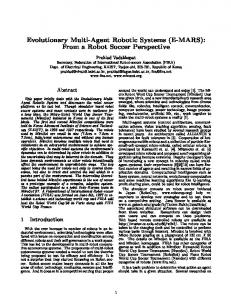
FIG. 15. 共Color兲 Polar plots of the snow HDRF shown in Fig. 14 for all view angles for six wavelengths across the solar spectrum. The radial distance from the center of each plot represents the view zenith angle. Rotation about the center represents a change in azimuth. The azimuth angle of 0° is the forward reflectance half of the solar principal plane and illumination comes from an azimuth angle of 180°.
FIG. 14. Snow HDRF spectra 共left兲 collected with the ASG with 0 ⫽47° at 10° angular resolution. The top plots correspond to a view azimuth of r ⫽0°, the middle plots correspond to a view azimuth of 90°, and the bottom plots correspond to a view azimuth of 180°. The surface grain size, estimated with stereological analysis, was ⬃240 m.
of the speed of acquisition, the fine angular resolution, and the spectral range and resolution of the spectrometer. The HDRF of snow is largest in the forward reflectance direction ( r ⫽0°), increasing with view zenith angle r 共Fig. 14兲 due to strong forward single scattering by snow grains. The relative increase in HDRF with r increases with wavelength. Figure 15 shows the angular structure of the HDRF at distinct wavelengths. The HDRF structure changed from convex about the forward reflectance direction at shorter wavelengths 共⫽0.55 m兲 to concave about the for-
ward direction at longer wavelengths 共⫽2.25 m兲. This change with wavelength is due to the change in the reflectance properties of snow from multiple scattering at shorter wavelengths to single scattering 共in turn due to the several order of magnitude increase in the imaginary part of the complex refractive index兲 and the structure of the singlescattering phase function of the snow grains 共which depends on the shape and size distribution of the snow particles兲.1 Measurements of the HDRF with the ASG are accompanied by measurements of the atmospheric optical properties from a sun photometer 共optical depths of Rayleigh scattering, oxygen, aerosols, and water vapor兲 and measurements of the snow physical properties 共grain size, grain morphology, snow liquid water content, temperature, snow depth, and snow density兲. The HDRF measurements represent the reflected radiance field at the bottom of the atmosphere, whereas a satellite measures one direction in this radiance field convolved with transmission through and scattering and
Downloaded 17 May 2004 to 128.111.111.217. Redistribution subject to AIP license or copyright, see http://rsi.aip.org/rsi/copyright.jsp
5188
Rev. Sci. Instrum., Vol. 74, No. 12, December 2003
absorption by the atmosphere. Therefore, the ASG HDRF measurements are used as a validation or boundary condition for an atmospheric transmission model coupled with a remote sensing inversion model. Laboratory measurements of directional reflectance lack a diffuse irradiance component 共that is, they are truly bidirectional reflectance measurements兲 and are therefore one step removed from the radiance field sampled by the satellite. It should be noted though that in alpine terrain, atmospheric optical depths are small, and therefore diffuse irradiance decreases with increasing wavelength. At wavelengths greater than ⬃1.0 m, the HDRF and bidirectional reflectance factor are nearly identical.7 Coupling these data with measurements of snow properties in the field facilitates improvements to radiative transfer models of snow optical properties and ultimately models that invert remotely sensed data for spatial distributions of snow properties. For example, Leroux et al.2 made measurements of the directional reflectance of snow in the near infrared. They demonstrated that results from their radiative transfer model26 better matched the directional reflectance measurements if hexagonal particles were used for single-scattering calculations rather than spheres. Furthermore, Painter et al.27 used a similar radiative transfer model to generate a spectral library of snow spectral directional reflectance to invert imaging spectrometer data for fractional snow cover, grain size, and albedo in alpine drainage basins. The improvements in physical property retrievals provided by the incorporation of knowledge of the directional reflectance of snow will ultimately improve snow hydrologic modeling in rough terrain.4,28 The scale of the ASG permits application to other smooth surfaces such as desert, soil, tundra, and pavement. The authors are currently generating a database of high angular and spectral resolution HDRF measurements with the ASG. The data can also be made available to incorporation into databases such as the Columbia-Utrecht Reflectance and Texture Database29 and that being provided with a coming text on field measurements of directional reflectance.30 ACKNOWLEDGMENTS
The authors thank Mark Shier and Hamid Baheri for their assistance with the design of the automated spectrogoniometer. They also thank Paul Ricchiazzi, William O’Hirok, James Wilson, and Michael Colee for discussion and suggestions. Rincon Engineering of Carpinteria, CA, machined the components of the ASG.
Painter, Paden, and Dozier S. G. Warren, Rev. Geophys. Space Phys. 20, 67 共1982兲. C. Leroux, J. L. Deuze, P. Goloub, C. Sergent, and M. Fily, J. Geophys. Res., 关Atmos.兴 103, 19721 共1998兲. 3 Z. H. Jin and J. J. Simpson, IEEE Trans. Geosci. Remote Sens. 37, 543 共1999兲. 4 T. H. Painter and J. Dozier, Remote Sens. Environ. 共in press兲. 5 K. Stamnes, S.-C. Tsay, W. J. Wiscombe, and K. Jayaweera, Appl. Opt. 27, 2502 共1988兲. 6 M. Mishchenko, J. M. Dlugach, E. G. Yanovitskij, and N. T. Zakharova, J. Quant. Spectrosc. Radiat. Transf. 63, 409 共1999兲. 7 F. E. Nicodemus, J. C. Richmond, J. J. Hsia, I. W. Ginsberg, and T. Limperis, Report No. 160 共1977兲. 8 C. Bruegge, N. Chrien, and D. Haner, Remote Sens. Environ. 76, 354 共2001兲. 9 H. O’Brien and R. H. Munis, Report No. 332 共1975兲. 10 K. Steffen, in Large Scale Effects of Seasonal Snow Sever, edited by B. Goodison, R. G. Barry, and J. Dozier 共IAHS Publication 166, Wallingford, UK, 1987兲, pp. 415– 425. 11 T. C. Grenfell, S. G. Warren, and P. C. Mullen, J. Geophys. Res., 关Atmos.兴 99, 18669 共1994兲. 12 J. Dozier, R. E. Davis, A. T. C. Chang, and K. Brown, in The Spectral Bidirectional Reflectance of Snow 共Aussois, 1988兲, pp. 87–92. 13 Optronik Goniophotometers, http://www.pro-lite.uk.com/Optronik/ optronik.htm, 2003. 14 S. C. Foo, Master’s thesis, Cornell University, 1997. 15 D. L. MacAdam, Color Measurements Theme and Variations 共Springer, Berlin, 1981兲. 16 S. R. Marschner, E. O. F. Lafortune, S. H. Westin, K. E. Torrance, and D. P. Greenberg, Report No. PCG-99-1, 1999. 17 D. Deering and P. Leone, Remote Sens. Environ. 19, 1 共1986兲. 18 C. Bruegge, M. C. Helmlinger, J. E. Conel, B. J. Gaitley, and W. A. Abdou, Remote Sens. Rev. 19, 75 共2000兲. 19 S. R. Sandmeier and K. I. Itten, IEEE Trans. Geosci. Remote Sens. 37, 978 共1999兲. 20 T. Aoki, M. Fukabori, A. Hachikubo, Y. Tachibana, and F. Nishio, J. Geophys. Res., 关Atmos.兴 105, 10219 共2000兲. 21 Analytical Spectral Devices, Inc., http://www.asdi.com/, 2003. 22 L.-W. Tsai, Robot Analysis The Mechanics of Serial and Parallel Manipulators 共Wiley, New York, 1999兲. 23 S. Sandmeier, C. Muller, B. Hosgood, and G. Andreoli, Remote Sens. Environ. 64, 176 共1998兲. 24 R. O. Green 共Jet Propulsion Laboratory, Pasadena, CA兲. 25 Labsphere, Incorporated 共X-rite Incorporated兲, www.labsphere.com, 2003. 26 C. Leroux, J. Lenoble, G. Brogniez, J. W. Hovenier, and J. F. De Haan, J. Quant. Spectrosc. Radiat. Transf. 61, 273 共1998兲. 27 T. H. Painter, J. Dozier, D. A. Roberts, R. E. Davis, and R. O. Green, Remote Sens. Environ. 85, 64 共2003兲. 28 N. Molotch, T. H. Painter, R. Bales, and J. Dozier, Geophys. Res. Lett. 共2003兲. 29 Columbia-Utrecht Reflectance and Texture Database, http:// www1.cs.columbia.edu/CAVE/curet/.index.html, 2003. 30 C. J. Bruegge, M. Schaepman, G. Strub, U. Beisl, A. Demircan, B. Geiger, T. H. Painter, B. E. Paden, and J. Dozier, Outdoor Measurements of BRDF, in Reflection Properties of Vegetation and Soil—with a BRDF Data base 共Wissenschaft and Technik, Berlin, 2003兲. 1 2
Downloaded 17 May 2004 to 128.111.111.217. Redistribution subject to AIP license or copyright, see http://rsi.aip.org/rsi/copyright.jsp