tems: reactive control systems, and web applications. A subset of ... Our aim is automate development steps as far as possible, to reduce developer effort and the ...
Automated Synthesis of High-Integrity Systems using Model-Driven Development K. Lano, K. Androutsopolous Dept. of Computer Science, King’s College London, Strand, London, WC2R 2LS, UK
Abstract. Model-driven development (MDD) is the construction of software systems using formal or semi-formal design models as the basis. One potential benefit of MDD is that the construction of software from models can be automated, to reduce development costs and errors. We describe the application of MDD to two areas of high-integrity systems: reactive control systems, and web applications. A subset of UML with a precise semantics is used to support analysis and verified model transformations.
Keywords: Model-driven development; UML; MDA; Verification
1
Introduction
The Model Driven Development (MDD) concept envisages a future where software systems are increasingly developed as higher-level models rather than lowlevel code. This vision intends to make the production of software systems more reliable and efficient by freeing developers from the complexity of implementation details on particular platforms. One approach to MDD is the Object Management Group’s (OMGs) Modeldriven Architecture (MDA) initiative [27], which aims to improve portability and reusability of software systems by creating platform-independent models (PIMs) from which versions of the system appropriate to particular technologies/languages can be generated, semi-automatically, via platform-specific models, PSMs. One common notation used to express MDA models is the Unified Modelling Language (UML) [25]. Here we will use a subset, UML-RSDS (Reactive System Development Support), of UML which is sufficiently expressive for many purposes, and which also has a precise semantics [20, 18]. UML-RSDS combines formal and object-oriented approaches to software development, providing the benefits of formal development without requiring formal methods expertise. As with U2B [28], UML-RSDS can be used as the starting point of a fully formal development using the B language. In conventional UML development, constraints in the OCL notation1 are mainly used as class invariants and as operation pre and post conditions. How1
OCL is a functional language, formally adopted as part of the UML 2.0 standard.
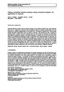
ever there is also a need to specify the global behaviour of a system in an abstract declarative manner, and UML-RSDS uses an adaption of OCL to define constraints relating several classes. Finally, the formal semantics of UML-RSDS can be used to justify PIM to PIM transformations and PIM to PSM refinements, providing a rigorous basis for an MDA approach. Figure 1 summarises the development process supported by UML-RSDS and its accompanying toolset. A developer can construct PIM or PSM class diagrams and state machines using the tool, analyse these for conformance to the UML or platform-specific metamodel (currently only Java and Java-based web applications are supported), transform models to improve their quality or refine them, translate to B [1] or SMV [12] for semantic analysis, and generate Java code from a Java PSM. A specific tool for generating web applications (using Servlets or JSPs in an MVC architecture) from class diagrams is also provided. Our aim is automate development steps as far as possible, to reduce developer effort and the risk of error introduction in manual processes. A PIM may need to
Consistency, Completeness checking
UML−RSDS Specifications PIM level
Proof, animation B Synthesis
Refinement transformations
Quality improvement transformations
SMV Synthesis
B Specification
UML−RSDS Specifications PSM level
SMV Specification Model checking
Synthesis of Java
Testing
Automated step Semi−automated step Manual step
Java Code
Fig. 1. UML-RSDS Development Steps
be transformed into a PSM before code generation can be applied, for example, to eliminate multiple inheritance or (for a relational database implementation) many-many associations. Section 2 defines the UML-RSDS notation, Section 3 describes the UMLRSDS tools. Section 4 describes the UML-RSDS process for synthesis of reactive systems, and Section 5 describes the process for synthesising web applications. Section 6 describes some related work.
2
Specification in UML-RSDS
UML-RSDS specifications consist of:
1. A UML class diagram, including constraints (expressed in a subset of OCL [20]) attached to operations, classes and (sets of) associations; 2. State machine models attached to classes in the class diagram, or to use cases. 3. Use cases, describing the operations which a user of the system described by the specification can perform on it. Attributes of a class can be stereotyped as input , internal , derived or output . Derived attributes are prefixed by / as usual. The prefix ? indicates an input attribute and ! an output. These stereotypes are applicable for many different kinds of system, for example, an input field on a web page, or a sensor in a process control system, could both be represented as input attributes. 2.1
Specification Example
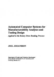
An example of a UML-RSDS specification, of part of a robot control system [23], is shown in Figure 2.
FeedBelt
ERTable 1
*
? fbsw: State ? fbend: State ! fbm: State
belts
*
? ertblank: State ? ertts: State ? ertbs: State ! ertrm: RotMovement ! ertvm: VertMovement
C3, C4 1
1
C1, C2
1
ProductionCell ok: Boolean
State Off On
RotMovement Off Clockwise Anticlockwise VertMovement Off Up Down
Fig. 2. Class Diagram of Production Cell System
The FeedBelt class represents feed belts, which move work pieces (such as car bodies) into the robot production cell. These have a motor fbm to move the belt, a switch fbsw to switch the belt on and off, and a sensor fbend to detect if a piece has reached the end of the belt, ready for unloading into the next component of the cell.
One such component is an ‘elevating rotating table’, represented by the ERTable class. These tables have two motors ertvm for vertical movement and ertrm for rotary movement, and two sensors ertts and ertbs to detect if the table is at its top or bottom position, respectively. The sensor ertblank detects if there is a work piece in the table. Normally one or more feed belts may feed blanks into a given table. belts gives, for each table, the set of belts that feed that table. Some example constraints in this system are: – C 1 “If the belt switch is off, the motor is off”: fbsw = Off ⇒ fbm = Off – C 2 “If there is no blank at the end, the belt keeps moving”: fbsw = On & fbend = Off ⇒ fbm = On These are local invariants of the FeedBelt class. Constraints which link the feed belt and table classes are: – C 3 “If a belt is ready to unload, and its table is ready to receive a blank, then unloading may proceed”: fbsw = On & fbend = On & ertblank = Off & ertts = On ⇒ fbm = On – C 4 “If a belt is ready to unload, and its table is not ready to receive a blank, then unloading may not proceed”: fbsw = On & fbend = On & ertblank = On ⇒ fbm = Off fbsw = On & fbend = On & ertts = Off ⇒ fbm = Off C 3 and C 4 are constraints on the association between FeedBelt and ERTable: they specify that, for any pair of feed belt and table objects linked by this association, that the given invariants must hold true. In this system the association represents the physical connection between the robot system components: that the belt is positioned to feed blanks to the table. 2.2
UML-RSDS Constraints
OCL can be used to define constraints in a UML-RSDS model. The significant extension of UML-RSDS over standard UML class diagrams is that constraints may be attached to associations. Association constraints permit a more abstract and less implementation biased specification of properties than OCL navigation expressions: which always express a property starting from the context of a
< value >
::= < ident > | < number > | < string > | < boolean > < objectref > ::= < ident > | < objectref >.< ident > | < objectref > |( < expression > ) < arrayref > ::= < objectref > | < objectref >[< value >] < factor > ::= < value > | { < valueseq > } | Sequence{ < valueseq > } | < arrayref > | < factor > op1 < factor > < expression1 > ::= < factor > op2 < factor > < expression > ::= < expression1 > | ( < expression > ) | < expression1 > op3 < expression > < invariant > ::= < expression > | < expression > => < expression >
Variable expression. Primitive literal expressions. Navigation call expression. Select expression. At expression. Collection literal expressions. Infix binary operation call (1) Infix binary operation call (2)
Infix binary operation call (3)
Table 1. UML-RSDS Constraint Syntax
particular class, so biasing the specification towards implementations in which that class is responsible for maintaining the constraint. Table 1 shows the syntax of OCL expressions currently accepted in UMLRSDS constraints, within the UML-RSDS tools. A valueseq is a comma-separated sequence of values. A factor level operator op1 can be: 1. +, −, ∗, /, div , mod 2. \/, /\ (also written as ∪ and ∩), a. A comparator operator op2 is one of =, /=, , =, :, < expression > | < modalops > (< modalops >< expression > ⇒ < modalops >< expression >)
where < modalops > is a (possibly empty) sequence of modal operators. Table 3 explains the meaning of these operators. Operator Meaning AX ψ ψ holds in all immediate next states of the current state. EX ψ ψ holds in at least one immediate next state. AGψ ψ holds in all future states. EGψ ψ holds in all future states of some path from the current state. AF ψ For each path from the current state, ψ holds in some future state of that path. EF ψ There is a future state satisfying ψ. Table 3. Temporal logic operators of CTL
An automated translation from UML-RSDS to SMV provides a means for verification of such properties of a specification [3]. This translation maps each class into a SMV module, with arrays being used in SMV to model the collection of objects of each class, and to model associations between classes. Modules are parameterised by an object identifier. Only systems with a bounded number of objects can be translated to SMV: each class must have a cardinality constraint defining the maximum number of objects of the class that can exist. An example of translation to SMV is a translation of a simplified FeedBelt class, which has only the fbend attribute ([3]): MODULE FeedBelt(C,id) VAR fbend : {Off, On}; alive : boolean; ASSIGN init(fbend) := Off; next(fbend) := case C.event = setfbendOn & alive & C.feedbeltId = id : On; C.event = setfbendOff & alive & C.feedbeltId = id : Off; 1 : fbend; esac; init(alive) := 0; next(alive) := case C.event = newFeedBelt & C.feedbeltId = id : 1;
C.event = killFeedBelt & C.feedbeltId = id : 0; 1 : alive; esac;
C is a parameter which will be instantiated with the controller module of the system, which holds a variable event denoting the current input event detected by the system: creation or deletion of a feed belt, or a change of attribute state. Also in the controller is a variable feedbeltId which identifies which feed belt object is the target of the event. The parameter id denotes the actual identity of a specific feed belt object, and the variable alive indicates if the object exists or not. It is 0 (false) initially. To create an SMV model with five feed belts, the following main module would be defined: MODULE main VAR MFeedBelt0 : FeedBelt(C,0); MFeedBelt1 : FeedBelt(C,1); MFeedBelt2 : FeedBelt(C,2); MFeedBelt3 : FeedBelt(C,3); MFeedBelt4 : FeedBelt(C,4); C : Controller; SPEC // properties to be proved
Predicates in CTL syntax can be written in the SPEC clause of this module. A predicate which in UML-RSDS implicitly constrains the state of several objects (all instances of a class, or all objects connected by an association) must be explicitly expanded to refer to specific objects. For example, a temporal class invariant “if the feed belt end is occupied then eventually it will become unoccupied”: AG(fbend = On ⇒ AF (fbend = Off )) would be encoded as AG(MFeedBelt0.fbend AG(MFeedBelt1.fbend AG(MFeedBelt2.fbend AG(MFeedBelt3.fbend AG(MFeedBelt4.fbend
= = = = =
On On On On On
-> -> -> -> ->
AF(MFeedBelt0.fbend AF(MFeedBelt1.fbend AF(MFeedBelt2.fbend AF(MFeedBelt3.fbend AF(MFeedBelt4.fbend
= = = = =
Off)) Off)) Off)) Off)) Off))
& & & &
Running the SMV tool on such a specification will either confirm that these predicates hold over all the possible traces of behaviour of the model, or will produce counter-example traces for which they fail. The correctness of the translation to SMV is verified by providing a common semantics for SMV and UML, and demonstrating that the SMV translation T (e) of any UML element e has the same semantics as e [3].
4.5
Production of a PSM
Once the PIM models have been verified as consistent, complete and valid, transformations can be applied to refine the PIM towards a PSM for a particular platform. In UML-RSDS this is performed by selecting an appropriate transformation and applying it to a model. The application of the transformation is carried out automatically by the UML-RSDS toolset. Each transformation is proven to preserve the semantics of the model, so that a correct PIM yields a correct PSM. Examples of transformations for a Java PSM are [22]: 1. Removing multiple inheritance, either by amalgamation of classes and subclasses, or replacing inheritance by an association. 2. Removing association classes, replacing them by two many-one associations and a new constraint. Other transformations can be used to improve the quality of a model (PIM or PSM) by refactoring/restructuring. For example, the introduction of a Template Method pattern structure. It is also possible to introduce new transformations, and to verify the correctness of these by using the B translation, and refinement proof in B [21]. 4.6
Generation of Java
Java code can be generated automatically from a Java PSM, using the same algorithm for converting constraints into explicit update operations as is used in the translation to B. However the structuring of Java is closer to UML than is B, resulting in a very close correspondence between the specification and implementation: each UML class becomes a Java class, each data feature of the UML class becomes a corresponding instance variable of the Java class, etc.
5
Development Process for Web Applications
In contrast to the usual ‘fine grain’ functional specification for which formal methods are usually applied, with web applications formal specification can be used to ensure the data integrity and consistency of the system at a large scale. For web applications, the development process consists of the following steps: 1. Identification of logical data model of system, expressed as a PIM class diagram. 2. Identification of use cases of system. 3. Transformation of data model into a platform-specific (usually relational data storage) data model. 4. Selection of required architecture: Servlet-based, JSP-based, or J2EE. In each case a model-view-controller separation of the components of the system is used.
The following transformations are used to convert the PIM data model into one suitable for implementation in a relational database: – – – –
Removing inheritance. Removing many-many associations. Introducing primary keys (for persistent classes). Replacing many-one associations by foreign keys.
A UML profile for web applications is used to guide the use of these transformations and the code generation process (Figure 3). Form Class
Explicit
Implicit
Persistent Association
Identity
Attribute
ForeignKey
Add Remove
Create
Operation
List Edit
Get
Delete
Fig. 3. Profile for Web Applications
For example, an implicit association is implemented using SQL queries, not by a physical database table. The OCL predicate defining membership of the association can be directly used as the predicate of the SQL SELECT statement which identifies the current members of the association according to the database data. Automatic generation of web applications can ensure that the visual presentation and interaction style of the system to clients is consistent across all web pages, and that standards for accessibility and usability are met. It also ensures a consistent internal design for the system, and that good design practices are followed. This is particularly important when complex frameworks such as J2EE are used [13]. Finally, the generated code can be guarenteed to be functionally correct.
Three alternative code-generation strategies can be used to generate the web pages, server-side processing components and database management components of a web application from PSMs: 1. JSP-based architecture: JSPs are used as view components to produce client input forms and query result web pages. Beans are used to process requests and perform database interaction. 2. Servlet-based architecture: specialised Java classes are used to generate web pages, these pages are returned as the result of servlet doGet or doPost operations. Servlets coordinate request handling and database interaction. 3. J2EE-based architecture: entity beans are used to provide an object-oriented wrapper for database data, and session beans are used to encapsulate transactions and other operations on this data. Presentation functionality is handled by a combination of servlets and JSPs.
6
Related Work
Related work on UML is the U2B tool of Butler [28], and translations [15] from UML to Object-Z. Other approaches that use model-checking for UML are the system of [14] for property checking of statecharts using SPIN, and the Hugo tool of [17]. A general problem with UML model checking is the semantic gap between the UML languages and the (typically very restricted) language of the model checker. To reduce the size of the generated SMV, we use a two-level semantic approach for state machines, a coarse-grain semantics, which abstracts from the order of actions within an event reaction (as in the B translation), and a fine-grain semantics, which includes the ordering information (as in the Java translation) [3]. We have also used mappings from UML to SMV which reduce model size: for example, representing associations as single two-dimensional arrays instead of as one-dimensional arrays embedded in each object. UML-RSDS is similar in intent to pragmatic formal approaches such as SCR [7]. However, instead of inventing a new diagrammatic formal method, we make precise an existing widely-used semi-formal method. Some related UML tools are: (i) The KeY System. This toolkit [2] provides facilities for verifying object-oriented applications against OCL specifications. In contrast to KeY, UML-RSDS is intended to be used by developers as an OO formal method, and to generate applications from high-level models according to the MDA [27] concepts. UML-RSDS has also established a modular design methodology including modular verification, which is lacking in KeY. (ii) Executable UML [24]. UML-RSDS has a similar motivation to Executable UML, but uses more abstract specifications as its starting point, instead of the operational statechart-based models of Executable UML. This has the advantage of providing analysis and error-detection at an earlier development stage.
7
Conclusion
We have introduced a notation and process, supported by tools, for the application of MDD and MDA concepts to critical systems, starting from highly abstract and declarative UML specifications. UML-RSDS enhances the benefits of UML as a notation for expressing requirements, and enables communication between customers and developers of a system, by allowing behavioural specifications to be defined at an early development stage (in PIMs or CIMs in MDA terms), whilst providing verification, transformation, error detection and code generation capabilities at this level.
References 1. J-R Abrial. The B Book: Assigning Programs to Meanings. Cambridge University Press, 1996. 2. Ahrendt, W., Baar, T., Beckert, B., Giese, M., Habermalz, E., Hahnle, R., Menzel, W., Schmitt, P., The KeY approach: Integrating object oriented design and formal verification. Technical Report 2000/4, University of Karlsruhe, Department of Computer Science, Jan. 2000. 3. Androutsopoulos, K., Verification of Reactive System Specifications using Model Checking, PhD thesis, King’s College, 2004. 4. ClearSy System Engineering, Atelier B, http://www.atelierb.societe.com/, 2004. 5. B4Free, http://www.b4free.com, 2006. 6. B. Berard et al, Systems and Software Verification: Model-Checking Techniques and Tools, Springer-Verlag, 1999. 7. Bharadwaj, R., Heitmeyer, C., Model checking complete requirements specifications using abstraction. In Proceedings of Automated Software Engineering, 6, 37–68, 1999. 8. Patrick Behm, Paul Benoit, Alain Faivre, Jean-Marc Meynadier, Meteor: A Successful Application of B in a Large Project, in Proceedings of FM’99: World Congress on Formal Methods in the Development of Computing Systems, Toulouse, France, September 1999. Jeannette Wing, Jim Woodcock and Jim Davies (Editors). 9. Bicarregui, J., Lano, K., Maibaum, T., Objects, Associations and Subsystems: a hierarchical approach to encapsulation, ECOOP 97, LNCS, 1997. 10. B-Core UK Ltd., The BToolkit, 2005. 11. Borland Com, http://www.borland.com/, 2006. 12. Burch, J., Clarke, E., McMillan, K., Dill, D., Hwang, J., Symbolic Model Checking: 1020 States and Beyond, Proceedings of the Fifth Annual Symposium on Logic in Computer Science, 1990. 13. J Crupi, D Alur, and D Malks. Core J2EE Patterns. Prentice Hall, 2001. 14. M. del Mar Gallardo, P. Merino, E. Pimentelis, Debugging UML designs with model checking, Journal of Object Technology, vol. 1, no. 2, July-August 2002. 15. Kim, S., Carrington, D., A Formal Mapping Between UML Models and Object-Z Specifications, in ZB2000, LNCS Vol. 1878, Springer-Verlag, 2000. 16. T. King (1995), Formalising British Rail’s Signalling Rules, Praxis Plc, Bath. 17. A. Knapp, S. Merz, Model checking and code generation for UML state machines and collaborations, TOOLS 2002, Institut f¨ ur Informatik, Universit¨ at Augsburg. 18. Lano, K., Logical Specification of Reactive and Real-Time Systems, Journal of Logic and Computation, Vol. 8, No. 5, pp 679–711, 1998.
19. Lano, K., Clark, D., Androutsopoulos, K., Formalising Inter-model Consistency of the UML, UML 2002, Workshop on Consistency Analysis of UML. 20. Lano, K., Clark, D., Androutsopoulos, K., UML to B: Formal Verification of Object-oriented Models, IFM 2004. 21. Lano, K., Using B to verify UML Transformations, MODEVA workshop, MODELS 2006. 22. Lano, K., Catalogue of Model Transformations, http://www.dcs.kcl.ac.uk/staff/kcl/tcat.pdf, 2006. 23. C. Lewerentz, T. Lindner, Formal Development of Reactive Systems. Case Study Production Cell, LNCS Vol. 891. Springer-Verlag, 1995. 24. S Mellor, Agile MDA, http://www.omg.org/agile/, 2004. 25. OMG, UML 2.0 Specification, http://www.omg.org/uml/, 2005. 26. OMG, UML OCL 2.0 Specification, ptc/2005-06-06, http://www.omg.org/uml/, 2005. 27. OMG, Model-Driven Architecture, http://www.omg.org/mda/, 2005. 28. Snook, C., Butler, M., U2B – A tool for translating UML-B models into B, in Mermet J., (Ed.), UML-B Specification for Proven Embedded Systems Design, Chapter 6. Springer-Verlag, 2004.