... or UDP, the port information (operator, port number or a port number range) is manda- ... Example Rule 2 If the protocol used in an access list is TCP or UDP,.
Automated Validation of Service Configuration on Network Devices Sylvain Hall´e, Rudy Deca, Omar Cherkaoui, and Roger Villemaire Department of Computer Science Universit´e du Qu´ebec ` a Montr´eal C.P. 8888, Succ. Centre-ville Montr´eal (Canada) H3C 3P8 {halle,deca,cherkaoui.omar,villemaire.roger}@info.uqam.ca
Abstract. Due to the significant development of network services in the past few years, their validation has become increasingly difficult. The advent of novel approaches to the issue of validation is therefore vital for keeping services manageable, safe, and reliable. We present a model for the validation of service configurations on network devices. A service configuration is modelled by a tree structure, and its properties are described by validation rules expressed in terms of these tree elements. By using an existing logical formalism called TQL, we have succeeded in expressing complex dependencies between parameters, and in automatically checking these dependencies against real-world network descriptions in feasible time. Keywords: network service management, automated configuration validation Topic: policy-based management
1
Introduction
The recent years have seen significant development occurring in the domain of network services. In parallel to the creation of new services spreading in increasingly more diverse areas, the networks that support them have become integrated, leading to an increased heterogeneity in topologies, technologies, protocols, and vendors. Consequent to this booming, the validation of network services has become increasingly difficult: existing validation solutions haven been struggling to keep the pace but barely suffice anymore, and new solutions have been proposed, but are partial. The advent of novel approaches to the issue of validation is therefore vital for keeping services manageable, safe, and reliable. Some partial validation solutions have been proposed in different areas. For example, the authors in [2], [13] formally verify policy anomalies in distributed firewall rules. [3] develops a set of formal constraints under which a given Virtual Private Network is safe and properly working, but does not mention concrete implementations of the presented approach. J. Vicente and D. Hutchison (Eds.): MMNS 2004, LNCS 3271, pp. 176–188, 2004. c IFIP International Federation for Information Processing 2004 �
Automated Validation of Service Configuration on Network Devices
177
In this paper, we present a general-purpose model for the validation of integrity rules in service configurations on network devices. A service configuration is modelled by a tree structure, and its properties are described by validation rules expressed in terms of these tree elements. This allows efficient service validation on the managed network devices, minimises the effort, the errors and the cost for maintenance, consistency checking, and other stages of the service life cycle. Moreover, by using an existing logical tool called TQL [5], we have succeeded in expressing complex dependencies between parameters, and in automatically checking these dependencies against real-world configurations in feasible time. In sect. 2, we give a brief overview of typical network service properties and of their modelling in tree structures. Section 3 introduces the TQL tree logic and shows how service properties become validation rules expressed in this formalism, while sect. 4 presents the results of the validation of several configuration rules related to the Virtual Private Network service on multiple devices. Section 5 concludes and indicates further directions of research.
2
Service Configuration Properties
A service usually requires underlying services or sub-services, such as network connectivity, and has a life cycle starting from the customer’s demand and followed by negotiation, provisioning, up to utilisation by the customer and management of the service. Many steps of this life cycle, such as provisioning, entail the manipulation of configuration information in the devices involved in the service offering. The configuration information consists of parameters that can be created or removed and whose values can be changed according to a goal. The configuration process is hierarchical. Several parameters that logically belong together can be grouped together by means of configuration statements, such as commands or menu windows with buttons and choices. Thus, several parameters can be affected by means of a single command, and conversely, several commands can compose a single feature or a service, in the same way that several services can compose a higher-level service. Consequently, a provider of a higher level service can be a customer of a lower level service. 2.1
Dependencies at Service Configuration Level
The parameters and components of the configuration affected by a service are in specific and precise dependencies. All those dependencies must be studied and captured by the management models, in order to provide effective solutions. We will show some of those dependencies and a methodology for their modelling. For each of the examples presented, we will deduce a configuration rule formalising the dependencies. Example 1: IP Addresses. The existence or the possible state of a parameter may depend on another such parameter somewhere else in the configuration. The simplest example of such dependency can be seen in an IP address following the Classless Inter-Domain Routing (CIDR) scheme [10], [16], whose two
178
Sylvain Hall´e et al.
components, the value and the subnet mask, are linked by a simple relationship: an address like 206.13.01.48/25, having a network prefix of 25 bits, must carry a mask of at least 255.255.255.128, while the same address with a network prefix of 27 bits must not have a subnet mask under 255.255.255.224. From this example, we could deduce a simple rule ensuring the validity of all IP addresses used in a given configuration: Example Rule 1 The subnet mask of an IP address must be consistent with its CIDR network prefix. Example 2: Access Lists. Access lists show another example of a generic dependency. Network devices use access lists to match the packets that pass through an element interface and block or let them pass, according to packet information. The configuration of such extended IP access lists has a variable geometry: if the type of protocol used for packet matching is TCP or UDP, the port information (operator, port number or a port number range) is mandatory. If the protocol used is different (e.g. ICMP), there is no port information required. From this example, we could deduce another rule relating to proper use of access lists: Example Rule 2 If the protocol used in an access list is TCP or UDP, then this access list must provide port information. Access lists illustrate yet another parameter relationship: once an access list is created, an identifier is provided for it. This identifier must then be used to attach the access list to a specific interface. Example 3: Virtual Private Networks. More complex situations can be encountered, in which the parameters of several devices supporting the same service are interdependent. An example is provided by the configuration of a Virtual Private Network (VPN) service [15], [17], [18]. A VPN is a private network constructed within a public network such as a service provider’s network. A customer might have several sites, which are contiguous parts of the network, dispersed throughout the Internet and would like to link them together by a protected communication. The VPN ensures the connectivity and privacy of the customer’s communications between sites. The establishment and validation of VPN is a particularly interesting example that has already spawned many books and papers. In particular, [3] develops a set of formal constraints under which a given VPN is safe and properly working. [6] also uses the VPN as an example to present a formal method of validation. Some part of the connections and communications is realised between the routers at the edge of the provider’s network, called provider edge or PE-routers, and routers at the edge of the customer’s sites (customer edge routers or CErouters). Another part of the connections is made among the PE-routers of the provider’s network.
Automated Validation of Service Configuration on Network Devices
179
One of the many implementations of the VPN is based on Multi-Protocol Label Switching (MPLS), in which the connectivity and communications inside the provider’s network are ensured by the Border Gateway Protocol (BGP) processes. A simple way to realise it is by direct neighbour configuration. Among other requirements of this method, an interface on each PE-router (for example, Loopback0), must have its IP address publicised into the BGP processes of all the other PE-routers’ configurations using the neighbor command [15]. If one of these IP addresses changes the connectivity is lost and the VPN service functioning is jeopardised. Thus, Example Rule 3 In a VPN, the IP address of the Loopback0 interface of every PE-router must be declared as a neighbour in every other PErouter. Some of the dependencies might be specific to the vendor implementation of the configuration interface. Such dependencies are of a low level and more difficult to model, because of the diversity of the vendor solutions. For instance, the configuration commands in Cisco’s IOS are different from those in Juniper’s JunOS, not to mention the different versions of the same vendor’s commands. In the following sections, we rather focus on generic dependencies. 2.2
Configuration Management Approaches
The International Telecommunications Union (ITU) defines a management model called TMN [12] based on the OSI management framework. Three logical layers of this model are involved in network service management: – the service-management layer (SML) – the network-management layer (NML) – the element-management layer (EML) The service-management layer takes charge of the connections to the users and the underlying connectivity between users and the provider (e.g. transmitting a video image to the customer). The network-management layer deals with the topology, the technology (IP, ATM, FR, ...), the protocols (ISDN, BGP, OSP, RIP, ...) and the devices (number, type, and role) used in the network. The element-management layer deals with the network elements, the configuration parameters (bandwidth, packet size, error rate, IP addresses, routing tables, access lists, etc.) and commands that describe or implement the service. Network service management can be done by various means: text-based commands, graphical user interfaces, menus, wizards. Routers and switches, like other equipment working in IP networks, are mostly configured by means of commands (around 90%, according to some estimates) running under an operating system, such as NetBSD, Cisco’s IOS, and Juniper’s JunOS. In this case, configuration files contain sequences of text commands. Usually, with some exceptions, the default information present in the routers and switches is not recorded in configuration files, but only the alterations of this information.
180
Sylvain Hall´e et al.
Configuration files are an important mean for service configuration on network elements. The manipulation of the configuration files contributes to the quick and easy configuring of the routers and switches. Given the important role played by the commands in the service configuration on equipments, it is important to study their properties and particularities in order to draw network element management solutions. 2.3
Modelling the Service Configurations
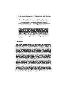
In this section, we describe how to model service configurations. All properties of a given configuration are described by attribute-value pairs. However, these pairs are organised in a hierarchy that will be represented by a tree structure. The tree representation is a natural choice, since it reflects dependencies among components, such as the parameters, statements and features. Moreover, trees are simple and handy for defining and performing various operations required by service management tasks. We will see that trees can also be put into direct correspondence with XML files for a better and easier manipulation. Tree Structures. The basic element of our tree structure is the configuration node which implements the concept of attribute-value pairs. A configuration node is in itself a small tree having a fixed shape. Its root is labelled node, and it has three children: – name, which itself has a single child of variable label, the name of the attribute – value, which also has a single child of variable label, the value of the attribute – child, which can have as many other node structures as desired Thus, if we are to speak of the IP address of a given component, we use the tree depicted in fig. 1.
Fig. 1. A simple configuration node
Were we to consider separately the value and the subnet mask of a given address, we could model it in the way represented by fig. 2. As one can see, our model puts the parameters as children configuration nodes. This approach enables to model simple dependencies among service configuration components, in which the existence of a component is conditioned by the existence of another. These dependencies are modelled by the ancestordescendent relationship.
Automated Validation of Service Configuration on Network Devices
181
Fig. 2. A configuration node with two children containing additional attributes
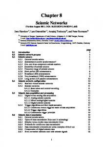
Fig. 3. Partial configuration tree structure for the access list example
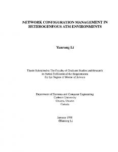
To illustrate this concept, let us examine fig. 3, which represents a sample tree for the access list presented in example 2 of section 2.1. In this tree, if the protocol parameter of an extended IP access list has the value TCP or UDP, it is the parent or ancestor node of the associated port node. The standard IP access lists do not have the protocol parameter and thus cannot have the port either. Under some systems, the access list number, stored at the root node of the access list tree, enables us to tell the difference between the two types. If the number is comprised between 1 and 99, the access list is a standard one; if the number is comprised between 100 and 199, the access list is of the extended type. Taking the concept of hierarchy further, we illustrate in fig. 4 by a larger tree the last example in section 2.1. Each router has a device name, an interface Loopback0 whose address is defined, and some number of neighbor attributes declaring the IP addresses of the neighbouring PE-routers. Figure 4 shows a portion of a tree for a single device named router\_1.
182
Sylvain Hall´e et al.
Fig. 4. Partial configuration tree structure for the VPN example
All our Example Rules given in sect. 2 can be translated into the new terminology of trees. Thus, Example Rule 3 becomes the following Tree Rule: Tree Rule 3 The value of the IP address of the interface Loopback0 in the PE router_i is equal to the IP address value of a neighbour component configured under the BGP process of any other PE router_j. This “tree-form” acts an an intermediate step between the English-like rules of sect. 2.1 and the formal syntax that will be introduced in sect. 3. To handle multiple devices in a same description, we can top all individual trees by a global common node, called network for instance. XML Schema Trees. XML (eXtensible Markup Language) is a universal format for structured documents over the web. XML is a widely used standard developed and maintained by the World Wide Web Consortium (W3C). Over the years, XML has gained in popularity and is becoming a standard way of representing virtually any data. There is a straightforward correspondence between labelled trees like the ones presented in sect. 2.3 and XML files. Any label in such a tree becomes an XML “tag”, and all children of that label are enclosed between its opening and closing tag. Hence, one configuration node produces many XML tags. The small tree of fig. 1 can be easily translated into this piece of XML code:
Automated Validation of Service Configuration on Network Devices
183
ip address 10.0.0.0 We do not include the XML versions of the other trees shown previously, as the translation is direct. XML is a natural choice of building and manipulating trees, because of its flexibility and the availability of a wide range of features and tools handling XML files. As shown in the first example of the previous paragraph, some complex dependencies cannot be seized by sole parent-children relationship. We hence need to introduce some kind of formalism and express rules applying to the tree elements (nodes, branches, values, root, etc.). This is what we do in the following section.
3
Modelling the Service Configuration Rules
With configurations described as trees, in order to verify configuration rules, we need a formalism to express properties of trees. Many such formalisms have been developed in recent years [1], [4], [9], [11], [14], [21]. In particular, [5] introduced a logic called TQL (Tree Query Logic), which supports both property and query descriptions. Hence one can not only check if a property is true or false, but also extract a specific subtree that makes that property true or false. We show in this section how TQL can be used to perform validation tasks on the XML network descriptions modelled in sect. 2. 3.1
A Formalism for Expressing Configuration Rules
Simply put, TQL is a description language for trees. We say that a tree t matches a given TQL expression e and we write t |= e when e is true when it refers to t. We also say that e describes t. The two main constructs in this logic are the edge ([ ]) and the composition (|). Any TQL expression enclosed within square brackets is meant to describe the subtree of a given node. For example, the expression root[child] indicates that the root of the current tree is labelled root, and that this root has only one child, labelled child. The composition operator joins two tree roots; hence, the expression node[name | value] describes a tree whose root is node, and whose two children are the nodes name and value. These operators can be nested at need; thus, the tree depicted in fig. 1 is described by the following TQL expression: node[name[ip address] | value[10.0.0.0] | child] Edge and composition alone can describe any single tree. To express properties about whole classes of trees, other operators are added to the syntax, whose intuitive meaning is given here:
184
Sylvain Hall´e et al.
– ¬A (negation): if a tree does not match A, then it matches ¬ A – A ∨ B (disjunction): if a tree matches A ∨ B, then either it matches A or it matches B (or both) – A ∧ B (conjunction): if a tree matches A ∧ B, then it must match both A and B – . (existence of a child): .x matches any tree whose root has a child labelled x These operators allow us to express, for example, the fact that a given access list has a port node if its protocol is TCP or UDP: TQL Query 2 node[name[protocol] | value[TCP ∨ UDP] | child[ .node.child.node[.name[port]]]]] ∨ It actually tells that the root node of the tree is labelled node, whose name branch leads to protocol, whose value branch leads to either TCP or UDP and whose child branch spawns another node leading to port. If not, then the root node has a protocol name different from TCP and UDP. A similar argument allows us to check that the tree shown in fig. 5 also verifies the property.
Fig. 5. Another access list tree with no port information
Furthermore, one can extract the protocol name in fig. 3 with the query node[.value[$P]] expressing the fact that the root node has a child labelled value having its child label assigned to variable $P. TQL rules are instantiated in a Prolog-like fashion. Let us also mention that TQL contains a fix-point operator which can be used to recursively express properties at any depth in a tree [4], [5]. This makes TQL suitable for any configuration property.
Automated Validation of Service Configuration on Network Devices
185
For more information related to TQL and its syntax, the reader is referred to [4] and [5]. 3.2
Applying TQL to Validate Service Configuration File Properties
Each of the Tree Rules to be checked on a given description can be translated into TQL queries by using the operators described above. For example, the VPN Tree Rule 3 now becomes: TQL Query 3 network[ .node[.name[device name] | .value[$N] | .child.node[ .name[interface type] | .value[loopback] | .child.node[ .name[interface number] | .value[0] | .child.node[ .name[ip address] .value[$A]]]]] ∧ .node[.name[device name] | .value[¬ $N] ∧¬ .child.node[ .name[bgp] | .value[100] | .child.node[ .name[neighbor] | .child.node[ .name[ip address] | .value[$A]]]]]] The first half of the query fetches all tuples of values of device_name and ip_address for the Loopback0 interface and binds them to the variables $N and $A. From all these tuples, the second half asks TQL to keep only those for which there exists a device different than $N where $A is not listed as a neighbour. The query returns all addresses of interfaces Loopback0 not declared as a neighbour in at least one other device. Therefore, if an inconsistency is detected, the set of faulty parameters is returned, thus helping to pinpoint the location of the error in the configuration and eventually correct it. On the other hand, an empty result indicates the property is verified for all addresses and all devices. The structure and syntax of these rules is straightforward, but cumbersome. However, the advantage of TQL over other tree logics is the availability of a software tool that automatically verifies TQL queries on XML files. This tool is freely available from TQL’s site [20]. The TQL tool takes as input an XML file containing the tree we want to check and TQL properties to be verified on that tree. The program performs the verification, and for each of the queries, outputs the portions of the tree that match the given property, if any. Moreover, once a TQL property is built to check a given rule, it does not need any modification to be checked against any schema tree following the same conventions.
4
Experimental Results
We processed real world XML network descriptions with the following 5 sample properties modelling the MPLS VPN service. Remark that property P4 is the VPN rule we have used as an example throughout this paper.
186
Sylvain Hall´e et al.
P1 If two sites belong to a single VPN, they must have similar route distinguisher and their mutually imported and exported route-targets must have corresponding numbers. P2 The VRF name specified for the PE-CE connectivity and the VRF name configured on the PE interface for the CE link must be consistent. P3 The VRF name used for the VPN connection to the customer site must be configured on the PE router. P4 The interface of a PE router that is used by the BGP process for PE connectivity, must be defined as BGP process neighbor in all of the other PE routers of the provider. P5 The address family vpnv4 must activate and configure all of the BGP neighbors for carrying only VPN IPv4 prefixes and advertising the extended community attribute. All these properties were translated into tree rules, and then into TQL queries in the same fashion as described in sect. 3. These queries were then verified sample XML schema trees of a network composed of 2 to 20 routers. These sample schema trees were automatically generated by a parameterisable script, and then directly fed to TQL. For some of the descriptions we used, one or many of the 5 rules were false. Since rules were processed separately, it was always possible to know which rule failed. The results, summarised in table 1, suggest a validation time roughly polynomial in the size of the configuration to check. Table 1. Results of TQL query validation for 5 VPN rules
Routers Config. nodes XML tags 2 56 413 4 224 1639 6 504 3681 8 896 6539 10 1400 10213 20 5600 40823
P1 0,04 0,06 0,09 0,12 0,15 0,52
Checking time (s) P2 P3 P4 P5 0,04 0,06 0,06 0,04 0,12 0,09 0,08 0,12 0,24 0,18 0,13 0,20 0,38 0,28 0,19 0,32 0,54 0,41 0,29 0,48 2,17 1,52 0,96 1,86
All results have been obtained on an AMD Athlon 1400+ system running Windows XP. As one can see from the previous results, validation time for all rules is quite reasonable and does not exceed 10 seconds for the largest data set. In all these sets, TQL correctly validated the rules that were actually true, and spotted the ones that did not apply.
5
Conclusions
We have shown how network configuration can be modelled first by using tree structures, and then by standard XML files. By using an existing logical formalism called TQL, we have succeeded in expressing complex dependencies between
Automated Validation of Service Configuration on Network Devices
187
parameters, and in automatically checking these dependencies against real-world network descriptions in feasible time. The results obtained suggest that this framework could be extended to model all kinds of dependencies in network descriptions for different classes of services. A subset of TQL could even be implemented in existing network management tools to perform background validation tasks and provide insightful messages to an administrator. The ability of TQL to formally detect and prove tautologies and contradictions could also be used to eventually discover conflicting rule sets. The scalability of our approach over networks of hundreds or thousands of devices must also be assessed. More experiments have to be done to ensure that validation time of larger descriptions remains in practical bounds. Further work towards a standardisation of descriptions of service configurations is also needed. The Common Information Model (CIM) [8] and Directory Enabled Networking (DEN) [19] initiatives developed by the Distributed Management Task Force (DTMF) [7] are two examples of an XML modelling of all components of network activity that opens the way to a normalisation of their behaviour.
References 1. Alechina, N., Demri, S., De Rijke M.: A modal perspective on path constraints. Journal of Logic and Computation, 13(6) (2003) 939–956. 2. Al-Shaer E., Hamed H.: Discovery of Policy Anomalies in Distributed Firewalls. Proc. IEEE INFOCOM (2004) 3. Bush, R., Griffin, T.: Integrity for Virtual Private Routed Networks. Proc. IEEE INFOCOM (2003) 4. Cardelli, L.: Describing semistructured data. SIGMOD Record, 30(4) (2001) 80–85 5. Cardelli, L., Ghelli, G.: TQL: A query language for semistructured data based on the ambient logic. Mathematical Structures in Computer Science (to appear). 6. Deca, R., Cherkaoui, O., Puche, D.: A Validation Solution for Network Configuration. Communications Networks and Services Research Conference (CNSR 2004), Fredericton, N.B. (2004) 7. Distributed Management Task Force. http://www.dmtf.org/ 8. DSP111, DMTF white paper, Common Information Model core model, version 2.4, August 30, 2000. 9. Fournet C., Gonthier G., L´evy J.-J., Maranget, L., R´emy, D.: A Calculus of Mobile Agents. Proc. CONCUR’96 (1996) 10. Fuller, V., Li, T., Yu, J., Varadhan, K.: Classless Inter-Domain Routing (CIDR): an Address Assignment and Aggregation Strategy. RFC 1519 (1993) 11. Gottlob G., Koch, C.: Monadic queries over tree-structured data. LICS’02 (2002) 189–202 12. ITU Recommendation M.3000, Overview of TMN Recommendations. February 2000. 13. Mayer, A., Wool, A., Ziskind, E.: Fang: A Firewall Analysis Engine. Proc. IEEE Symposium on Security and Privacy (2000) 14. Miklau G., Suciu, D.: Containment and equivalence for an Xpath fragment. Proc. PODS 2002 (2002) 65–76 15. Pepelnjak, I., Guichard, J.: MPLS VPN Architectures, Cisco Press (2001)
188
Sylvain Hall´e et al.
16. Rekhter, Y., Li, T.: An Architecture for IP Address Allocation with CIDR. RFC 1518 (1993) 17. Rosen, E., Rekhter, Y.: BGP/MPLS VPNs. RFC 2547 (1999) 18. Scott, C., Wolfe, P. Erwin, M.: Virtual Private Networks, O’Reilly (1998) 19. Strassner J., Baker F.: Directory Enabled Networks, Macmillan Technical Publishing (1999) 20. TQL web site, Universit` a di Pisa. http://tql.di.unipi.it/tql/ 21. Vitek, J., Castagna, G.: Seal: a framework for secure mobile computations. Internet Programming Languages, LNCS 1686 (1999) 44–77