e-mail: awf,az¡ @robots.ox.ac.uk. ABSTRACT. We describe a method to completely automatically ... plied to the automated recovery of VRML 3D textured mod-.
AUTOMATIC 3D MODEL ACQUISITION AND GENERATION OF NEW IMAGES FROM VIDEO SEQUENCES Andrew Fitzgibbon and Andrew Zisserman Dept. of Engineering Science, University of Oxford, 19 Parks Road, Oxford OX1 3PJ, UK awf,az � @robots.ox.ac.uk e-mail:
�
ABSTRACT
08
We describe a method to completely automatically recover 3D scene structure together with 3D camera positions from a sequence of images acquired by an unknown camera undergoing unknown movement. Unlike “tuned” systems which use calibration objects or markers to recover this information, and are therefore often limited to a particular scale, the approach of this paper is more general and can be applied to a large class of scenes. It is demonstrated here for interior and exterior sequences using both controlled-motion and handheld cameras. The paper reviews Computer Vision research into structure and motion recovery, providing a tutorial introduction to the geometry of multiple views, estimation and correspondence in video streams. The core method, which simultaneously extracts the 3D scene structure and camera positions, is applied to the automated recovery of VRML 3D textured models from a video sequence.
�
24
Through
Feature extraction
Through
Core: Simultaneous feature matching and geometry estimation
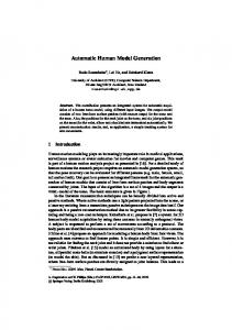
1 INTRODUCTION As virtual worlds demand ever more realistic 3D models, attention is being focussed on systems that can acquire graphical models from real objects. This paper describes a method for processing a sequence of images acquired by an unknown camera undergoing unknown movement to completely automatically recover 3D scene structure together with 3D camera positions. We employ Structure and Motion recovery results from the photogrammetry and computer vision literature, where it has been shown that there is sufficient information in perspective projections of a static cloud of 3D points and lines to determine the 3D structure as well as the camera positions from image measurements alone. The core system is an automatic process which can be thought of, at its simplest, as converting a camcorder to a sparse range sensor. Together with more standard graphical post-processing such as triangulation of sparse 3D point and line sets, and texture mapping from images, the system becomes a “VHS to VRML” converter — to acquire a realistic model of a 3D scene, a user must simply video it. The primary application is as a simple, automatic, accurate, and quick means of model acquisition to populate virtual worlds. Figure 1 shows a schematic overview of the system.
Matched features;
�����
projection matrices; 3D structure Through
Postprocessing: Triangulation / Plane fitting / Photogrammetry software
Figure 1: Overview of the system. Four frames from the 32frame input video sequence are shown at the top; views of the automatically acquired VRML model are shown at the bottom.
The key advantage of the approach we adopt is that no information other than the images themselves is required a priori: the camera pose is computed automatically from texture in the viewed 3D scene, so that neither calibration patterns nor 3D control points are required.
1.1 Background Although the general framework for uncalibrated structure from motion has been in place for some time [6, 14, 17] only recently have general acquisition systems come near to becoming a reality. This is because a combination of image processing, projective geometry for multiple views [13, 23, 25], and robust statistical estimation [28, 29] has been required in order to succeed at automating structure and motion algorithms [1, 16]. Tomasi and Kanade’s acquisition system [26] has much in common with ours, taking uncalibrated views and converting them to 3D structure. However there are several important differences: first, a simplified projection model is used, in our case the most general projection model applies. Significant perspective effects in the Kanade system (giving rise to vanishing points etc) will degrade the results. Second, their system uses a simple point tracker to find matches and does not employ robust statistics and rigid geometry for tracking—this severely limits camera motions and the type of acquisition scenes.
1.2 The scope of the approach The limitations of the approach of this paper can essentially be summarized by saying that the images must be sufficiently “interesting”—if the scene has no significant texture (to be defined more precisely later), then the feature based methods we use will have too few 2D measurements to work with; and second, that the camera motion between images needs to be relatively small, in particular rotation about the optical axis should be limited—otherwise the cross-correlation techniques used to match the features between images will fail. Happily, this restricted motion is the typical motion between frames of a video sequence, and the system is tuned for such data. We also require that the 3D scene be largely static, although smaller independently moving objects—shadows, highlights, passing cars and the like—are tolerated because of the use of robust statistics. The advantage of a video sequence, where the distance between camera centres (the baseline) for successive frames is small, is that correspondence between successive images is simplified because the images are similar in appearance. The disadvantage is that the 3D structure is estimated poorly due to the small baseline. However, this disadvantage is ameliorated by tracking over many views in the sequence so that the effective baseline is large. The accurate position of the 3D point or line is then computed by a bundle adjustment [24] over all views in which it appears.
2 THE CORE METHOD: CAMERAS FOR EACH FRAME, AND 3D POINTS AND LINES The core method is now described—the uncalibrated structure and motion algorithm. The core method is automatic, requiring no manual intervention at any stage. The house sequence of figure 1 will be used to illustrate the method throughout this paper. The key ideas are that the images of 3D entities (points, lines) satisfy relationships which are induced by the geometry of cameras viewing a rigid scene [7, 15]. These relationships are represented by tensors; in the two-view case the tensor is the fundamental matrix. These tensors can be computed from the image coordinates of a sufficient number of corresponding entities alone. The camera positions are then determined from the tensors, and given the cameras and correspondences the 3D structure can be recovered. Sections 3 to 5 describe the core system: the 2D feature extraction process, the geometry of multiple-view tensors, and the statistical estimation of the tensors from the 2D features. 3 FEATURE EXTRACTION In order to recover the 3D entities, their 2D images must be extracted from the input sequence. Two types of image primitives are used—interest points (“corners”) and line segments—extracted independently in each frame of the sequence using standard computer vision algorithms. These algorithms have the desirable property that the features they produce are generally the images of real 3D point and line features in the scene. Corners are detected to sub-pixel accuracy using the Harris corner detector [12]. Line segments are detected by: Canny edge detection at sub-pixel accuracy[4]; edge linking; segmentation of the chain at high curvature points; and finally, straight line fitting to the resulting chain segments. The straight line fitting is by orthogonal regression, with a tight tolerance to ensure that only actual line segments are extracted, i.e. that curves are not piecewise linear approximated. Further implementation details are given in [1], and examples are shown in figure 2b. 4 THE GEOMETRY OF MULTIPLE VIEWS: REVIEW We work in projective 2- and 3- space, representing geometric objects in homogeneous coordinates. In general bold uppercase is used for homogeneous 4-vectors and bold lowercase for image 3-vectors . Note that equations involving homogeneous primitives are defined only up to scale. This review is based on the following papers and books [2, 6, 9, 13, 14, 15, 18].
��
� ���������������� ������!�#"����
Perspective Projection A camera maps a point in 3D to a 2D image plane. The mapping is perspective (or central) projection, and is represented by a projection matrix, P, which projects a 3D point to its 2D image :
�& P
�$�%�
�
(1)
'
(
02
Reconstructed 3D point
03
Know these rays in 3D
(a)
Figure 3: The principle of triangulation. The known projection matrices P and P back project image points to 3D rays on which the 3D point lies. The 3D point position is recovered by intersecting the rays.
:
(b)
2. Know it must be on this ray
1. See this point
3. So it must be on this line
(c)
Figure 4: The epipolar line of a point (in the first view) is the image (in the second view) of the ray passing through the point in the first. The two images from the example sequence show a point selected in the first generating the line F in the second. The epipolar line of the 2D point in the first view passes through the image of the 3D point in the second view. The F matrix for these two views was computed automatically by the algorithm described in section 5.1.
�
(d) Figure 2: Image triplet processing: The workhorse of the system, converting a passive, uncalibrated, camera into a sparse range sensor. (a) The first three images of a 32-image sequence where the camera circumnavigates a toy house. (b) Point (white) and line (grey) features extracted from the sequence. (c) features matched across these three views. (d) Visualization of the recovered 3D structure and cameras.
�)�*�
The projection matrix has 12 elements but is only defined up to an overall scale (because it appears in homogeneous equations), and so has only 11 degrees of freedom. It may be computed from the correspondence of 6 or more 3D points and their images. The null-space of P, i.e. such that P , is the centre of projection of the camera.
+
+, .-
/
�
and these four constraints (over-) determine . This is triangulation, and is illustrated in Figure 3. It is the basis for all algorithms which recover 3D structure from 2D images. Epipolar Geometry and the Fundamental Matrix The images of a 3D point in two views obey a simple linear relationship. As shown in figure 4, corresponding points must lie on each other’s epipolar lines. This constraint is represented in homogeneous coordinates using the fundamental matrix:
�=�>�
� : � F& �