Automatic Image-Based Scene Model Acquisition and Visualization C. Vogelgsang, B. Heigl, G. Greiner, H. Niemann Informatik 5 and 9 – University of Erlangen – Nuremberg LGDV, Am Weichselgarten 9, 91058 Erlangen, Germany LME, Martensstr. 3, 91058 Erlangen, Germany Email: fVogelgsang,Heigl,Greiner,
[email protected]
Abstract In this paper we present the design and realization of an integrated automatic framework for capturing, reconstructing and rendering real world scenes with image-based techniques. We use uncalibrated 2D video streams from a consumer video camera recording the scene data in an overlapping move pattern and reconstruct a calibrated view sequence from it. This view data is then compressed and transformed to a lightfield representation used for storage and rendering. The system design allows the usage of different compression techniques and lightfield parameterizations. We show the different steps of the process chain and describe the details of the underlying system architecture and its modular design which is capable of transparently supporting various different file formats and data representations required at different stages. As a result we present the application of the framework with a sample scene. Finally we outline current limitations and possibilities for future extensions of the system.
1
Introduction
In the last years, image based techniques have been successfully applied in a lot of different task domains. These applications are mainly found in Computer Vision and Computer Graphics but also in disciplines like Information Coding or Image Communications. All of them have in common the usage of image information as a
primary source for the data derivation process. They share some common approaches, like the use of lightfield models but often differ in subtle details which were relevant for their specific work. As a consequence, all of these imagebased applications are derived from a common methodology but their applications differ too much, to be able to work in a combined framework. The development in the application-oriented field of image analysis and synthesis has shown that all involved disciplines have to work together and have to contribute their knowledge to achieve the common goal of creating automated systems for image analysis and synthesis. This synergetic process has worked out well in the section of pure abstract studies. In the next stage the unification must evolve to the level of application design and development. To support this evolution we have developed a common structure for the design of imagebased applications. The proposed framework tries to unify as many approaches as possible and provides a complete and extensible framework which should be well suited for a wide range of applications in the given task domain. In the following sections of this paper we start of (Section 2) by first describing common structures which proved to be useful in image-based modeling and offer a foundation for the further work. The components given there are fitted together in section 3 to form a general framework for image application tasks. In the next section 4 we show results which were achieved on a ref-
erence implementation of the proposed system. Finally we conclude (Section 5) and mention the future possibilities and current limitations of our work.
2
f t n l
Image-Based Structures
2.1 Image Data and Views The most important structure in the field of image-based rendering is the image itself. So the basis of our framework is a flexible description of image data. A first assumption is made about the layout of image information. We focus on a rectangular array of pixel information. This seems reasonable since most cameras capture rectangular pictures and in synthetic image generation this format is the only popular one. For other types of image data (e.g. spherical maps used in spherical lightfields [6]) the proposed structure can be easily adapted. The rectangular images are called maps and can store different information per pixel cell. Most common is a radiance map which stores samples of incoming radiance in physical quantities or in color (RGB) values. Other important per-pixel information is kept in a depth map where each cell contains depth information about the scene geometry at the given ray direction through the center of the cell. To successfully apply common image-based techniques like warping or lightfield rendering [2, 8] a geometric context for the image data is required. The map itself does not contain information about the camera which took the image. Therefore we introduced another structure called a view. A view combines a camera model with images taken by this camera at a given location and orientation. In the current realization of the system we focused on a simple pin-hole camera model with a freely defined viewing frustum. We found out that this model greatly matches a lot of commonly used cameras in image vision and synthetic rendering. Nevertheless this system is not limited to the proposed model and can easily be adapted to more elaborate camera models which use other types of projection (e.g. cylindrical maps [12, 1]).
r d
v
b
u
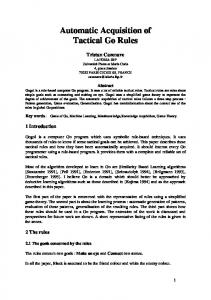
Figure 1: Parameters of a view.
A view is located at a given origin and oriented by a orthonormal coordinate system spanned by the vectors u, v and d (see Figure 1 for details). The perspective frustum is defined by (l; b) and (r; t) which are coordinates in the image plane parallel to u and v and that is located at distance 1 in direction d. The captured range of the scene is denoted by two distance parameters n (near plane) and f (far plane). All recorded depth information lies inside this range. A view holds any number of radiance and depth maps. The maps are stored in a map array and can have different image resolutions. This simplifies the usage of hierarchical techniques. It is required that all maps fill the whole region of the defined image plane. The implementations of the map type allow sparse maps so the size is no actual limitation to the concept and partial image information can be handled, too. Maps can also capture different depth ranges of the scene and layered depth images can also be realized [15]. Dynamic images (movies) are embedded by packing the individual frames into different radiance maps of a single view. To clarify geometric issues, we require the sample information to be taken at the center of each map cell. Another issue is the orientation of the map cell data in the camera image plane. The map pixel cells are numbered by tuples (i; j ) and running with increasing index from top to bottom and left to right. The vectors u and v define the right and up direction.
2.2 Lightfield and Scene A dataset of image-based information normally consists of hundreds or thousands of pictures. In our model we have the same number of associated view structures. The next step in our development was to organize this amount of data in a versatile way. The starting point was the existing description of the lightfield and the lumigraph (see [2, 8]). These structures can be interpreted as a regular grid of views with sheared frustum, aligned at the camera plane. Some remarkable features of this model are the simple addressing scheme of camera views by grid cell indices and the implicit topology information given in the grid. Other approaches [14, 3] extended this concept by introducing camera plane meshes which only require the camera origins to lie in a common 2D plane. To support other parameterizations like spherical [6] or free placement of cameras [4] the structure has to be extended even further. We finally defined the lightfield as a simple collection of views with additional structure information. This information is stored in a view mesh which describes the topology of the camera origins and the parameterization which maps parameter space coordinates to views. An implicit grid mesh is used for two-plane-parameterized lightfields, a 2D Delaunay triangulated mesh for sparse plane-to-plane lightfields and a 3D mesh for various free-form applications. To support hierarchies in the camera level we allow an array of different view meshes in each lightfield. So a detailed mesh can be used for exact reconstruction and coarser meshes are useful for far distance or real-time approximations. Finally, a complete scene is described as a collection of lightfields. The lightfields of a scene can describe different portions of the whole plenoptic function. It is not restricted to the spatial parameters of the function. This means that also dynamic aspects for future applications can be modeled. As an addition, the scene structure can contain some purely geometric information about the scene. These models may be required for special synthesis or analysis techniques. For example the lumigraph [2] requires depth informa-
Scene Geometry
Lightfield
View Mesh
View
Radiance Map
Depth Map
Figure 2: Components of the image-based foundation structure. Every arrow denotes a “maycontain-one-or-more” relationship between the objects. tion which can be extracted either from local depth maps stored in a view or from a coarse mesh approximation of the available objects in the scene. These meshes are kept in the global scene structure. Additional geometric data (e.g. detailed scene models) can be added to support the development of mixed geometric and imagebased applications, which combine best methods of both worlds. This allows for example the combination of fast image-based reconstruction with hardware-accelerated geometric rendering techniques. In the current implementation of the scene model, we only support simple triangle meshes as a coarse approximation of the scene where rays can be cast through to obtain depth information. As an extension to the framework, we think about adding lighting or object information to the scene, which can be reconstructed from the lightfields. So the scene structure initially stores only image-based information and can be gradually extended by higher level information which is reconstructed by special analysis modules of the system. In Figure 2 all components of the system’s foundation are presented.
3 System Design 3.1 Overview We investigated different applications of imagebased techniques and modeled a process chain
Scene
Capture
Registration
Remap
Codec
Codec
Render Analyse
Figure 3: Schematic overview of the proposed Framework. that encompasses most cases that occurred. All systems capture a given scene, transform the information into image-based structures and use them to analyze and visualize the data. The process uses a scene existing in reality or a pure virtual one as a starting point (see Figure 3). The visual appearance of this scene is captured in a set of images. They store different physical quantities like incoming radiance or local depth information. This is the basic set of image-based information. Then this recorded data is placed in a geometric context. This process is called calibration. In this process the radiance and depth maps are associated to their view structures. Also a lightfield is created which encapsulates the parameterization of the capturing setup. This also requires the definition of the view meshes. The next step in the process chain is called reparameterization. This step is optional but often required to get better performance for the further processing stages. The reparameterization transforms the captured lightfield data to a new parameter space with new view locations and/or map orientations. For example, fast rendering can be achieved with a two-plane-parameterized lightfield structure and so the commonly captured free form views are often remapped to this format. At the end of the process chain the system displays the lightfield data from new virtual camera positions. Here a new view from the scene is rendered very fast to give the user the impression of
free movement in the real scene. Another task is the analysis of the lightfield data. This step tries to reconstruct parameters of the visible objects out of the image data. Common methods extract object surface structures, material parameters including surface models or 3D voxel representations. A very important intermediate step between single modules of the system are the compression and decompression stages of the lightfield data. Since we handle image sets of hundreds or even thousands of images it is very important to keep this information very compact. Codec modules are placed in the process chain to handle automatic compression and decompression of map data. The data reduction techniques are mainly focused on maps since these data components require most space. The other structures describing geometry and lightfield layout are very small and usually need no special treatment. The codec modules are designed to act transparently between different “working” modules.
3.2 System Realization This described process chain has been applied to a specific system which first captures lightfields with a commercial hand-held video camera. Then a free form lightfield is reconstructed. The data is remapped to a two-planeparameterized lightfield and this is finally used for rendering to allow the user free navigation in the virtual scene model. 3.2.1 Capturing The capturing stage is a fairly easy process. We use a standard DV-Video camera to record a sequence of several hundred frames from the given scene. While recording, the camera is waved along a zig-zag pattern, so visible point features are trackable along consecutive frames and also between more distant frame numbers. Figure 4 shows a typical path of the camera. ¿From this procedure we get a fully uncalibrated image stream. This approach requires no special calibration setups or other preprocessing steps. So
Figure 4: Views of a captured free form lightfield. A line shows the connection between the recorded source frames. the user-involved part of the system is kept quite easy to handle and this is an important prerequisite for its widespread use. After capturing, a sequence of single RGB image frames in JPEG format is available. This is raw image information without the geometric context required for image-based rendering. So in the next step, the calibration tries to reconstruct this data. 3.2.2 Calibration The goal of calibrating the image stream is on the one hand to determine the position and orientation of the camera for each frame. On the other hand the goal is to retrieve its internal projection parameters like focal length and principal point. These are assumed to be varying because of the auto-focus mechanism of usual video cameras. To solve this problem many computer vision algorithms have been invented. One class of algorithms are those which determine the epipolar geometry between adjacent frames of the image stream by estimating the Fundamental matrix (see [9]). This is done by extracting point features and finding corresponding matches in other views by applying appropriate methods for finding outliers. In [7] we have adapted this approach for the special demands while calibrating extended image sequences taken by a handheld camera. By considering spatial neighborhoods of frames which are not neighboring in the
stream, the accumulation of small errors can be avoided and the calibration results are improved substantially. This method was used to achieve the results which are given in section 4. Another class of algorithms for calibrating image streams are the so-called factorization methods. The main idea is to build a matrix which contains all projections of scene points into all frames and factorize this matrix into one matrix containing all the pose and projection parameters of the camera and into another matrix containing all 3D coordinates of the scene points. When applying the projective factorization method [17] to real image sequences, the problem arises that not all feature points are visible in all frames because of occlusions and because they get lost during tracking them automatically. To solve this problem, we apply the method to partial sequences within whom enough points are fully visible and finally fuse the partial reconstructions [5]. Both of these methods result in a reconstruction of camera motion and scene points up to an unknown projective transformation. To calculate this transformation, so-called selfcalibration techniques are necessary, which assume that the image axes are orthogonal to each other. We use the method shown in [13]. After the calibration stage a free form lightfield structure has been created. Every image frame is assigned to a view with distinct orientation and location, an estimated pin-hole frustum and a dense depth map in image resolution. Additionally the reconstructed sparse depth maps can be stored in another layer of the view. 3.2.3 Reparameterization In the reparameterization module two lightfield structures are present, a source and a target lightfield. They are described by different geometries and view meshes. A conversion process then transforms the radiance and depth map information from the source lightfield to the target. The methods applied here are warping [14, 3] and rebinning techniques [2]. In our system we have to transform the free form views of the captured lightfield to a twoplane-parameterized lumigraph which can be
rendered with standard techniques. The first step in the conversion is the determination of suitable parameters for the target lightfield. In this case the two planes of the lightfield have to be specified. A placement is chosen which resembles the captured free form data, so as much information as possible can be reused. We use the following heuristic to choose suitable target planes: Find center of camera plane. This is done by finding the centroid of all view origins in the source lightfield. Find camera and image plane normal. Simply average all direction vectors d of all views in the source lightfield. Find camera plane dimensions. Project all source view origins on the camera plane and fit a 2D rectangle around the projected points. Make sure that the rectangle is centered around the chosen camera plane origin. Place image region. Since each source view has a depth range given by the “near” and “far” parameters, a suitable range for the image plane must be found there. We introduced a user controllable parameter called depth ratio ranging from 0 to 1, which denotes where to place the new image plane according to the source view frustums. 0 means placement at the near plane and 1 places the requested image plane at the far side of the frustum. With a given depth parameter a slice is cut out of each source view frustum. Then all four corners of each slice are projected on the camera plane and an average orthogonal distance is determined. This value is used for the image plane distance. The dimension of the image plane is the rectangle fitted around the projected four corner points of all source views. After calculating the geometric orientation and location of the target lightfield the user has to supply map sizes for the image and depth maps and a grid size for the camera plane. Since the system works fully automatically, these parameters must be directly deduced from the source lightfield parameters. As a heuristic, the map target size should be about half the source map di-
mensions, so artifacts caused by undersampling while reprojecting the views are tolerable. A good estimate for the camera grid size is the square root of the total view number in the source lightfield. This gives good results if the source views are distributed nearly uniformly in an area around the view rectangle on the target camera plane. The current implementation of the reparameterization module assumes that the source lightfield only captures frames which are suitable for a single two-plane-parameterized target lightfield. This is not always the case. If an object is captured from different directions it is necessary to use more slabs which are placed around the scene. Each slab then contains a single lightfield. To handle this case, we think about a preprocessing step in the reparameterization module which tries to split up source view clusters and then calculates the geometric parameters for a lightfield positioned in every cluster with the heuristic given above. After setting up both the source and target lightfield the remapping step begins. Every pixel cell of the source map has to be remapped to the target cells. We applied three different approaches here. The first method uses traditional warping techniques and first projects every pixel of a source map into the scene and then reprojects this one onto the target maps. The second module directly uses every ray through the source map cells and fills this information into the 4D structure of the target lightfield. No depth information is necessary in the second approach, however it can be used to improve interpolation quality (see [2] for details). We finally used an approach which uses warping techniques to change the projection center of each single camera such that it lies on the common plane of projection centers. This approach does not require an interpolation between different views. Both techniques can use hierarchical image maps to further improve quality by filling gaps and applying radiance interpolation of nearby mapped pixels or rays to better reconstruct the target map data. After the reparameterization step the newly created maps of the target lightfield are implic-
itly stored with a codec module to save space. 3.2.4 Rendering The final stage of the current system is the rendering module which allows the visualization of new virtual views of the captured scene. The applied techniques are based on the hardwareaccelerated rendering methods proposed for twoplane-parameterized lightfields and lumigraphs described in [2]. We additionally apply acceleration techniques specified in [16, 18] to fullfill real-time requirements (i.e. more than 10 frames per second) which are essential for a responsive system. The supplied view meshes of a lightfield structure can be directly used for fast textured triangle rendering. Different layers of radiance and depth maps are used for distance dependent resizing of the image maps and view mesh layers are applied to select the appropriate camera mesh resolution. Furthermore depth maps are directly used to improve the interpolation process. 3.2.5 Compression The codec module encapsulates the storage and restore process required for map handling. This flexible concept allows the implementation of different compression strategies without changing anything in the process chain. A codec is queried for specific maps of a view and has to load the requested portions from a coded stream and supplies decompressed data. On the other side, if a view is no longer necessary the data of the modified maps must be stored in the compression stream. A very important design issue derives from this handling concept: A codec must deliver a map at any position of the stream requested. This can be easily realized in single frame storage or movie frame sequences but may pose a problem for more efficient 4D compression schemes. The codec module has access to all parameters of the view and the containing lightfield. So besides well known per image compression techniques for the maps, more elaborate schemes can be applied which use coherence information provided by the view mesh structures of the light-
field. For two-plane-parameterized lightfield several approaches are described in [11, 10]. For the first stages of the system where free form lightfields are used, the geometric context is not so useful when coding maps. So we implemented a “movie stream” coder which stores every map layer in a separate one-frame-perview image stream. Standard movie compression techniques like M-JPEG and MPEG are applied and result in compact data files. This technique can be applied to both radiance and depth maps if the cell values are discretized and converted to a supported image format. Since the region of depth values is available for every view frustum, depth packing can be achieved easily. In the rendering module fast map retrieval is an important factor for real-time visualization. Since most map codec modules cannot decompress maps in real-time, the render module has to load the complete set of maps in a preprocessing step and then directly render from this data. This is not feasible for large lightfields and introduces delays in the setup of the rendering engine. So we developed a special codec module which uses hardware-accelerated movie decompression capabilities available on some platforms (e.g. SGI O2) to decompress map information in real-time. This codec does not use coherence information available in the lightfield and therefore the compressed data streams are not so small, but on the other hand, standard hardware can be applied to achieve the necessary real-time performance. Due to the modular design of the system the replacement of the codec module for the renderer requires no change in the implementation of the render code.
4 Results We illustrate the different steps of our system with a small example scene. It is called “desk” and shows some detailed objects lying on an office desk. We want to thank Reinhard Koch (University Kiel, Germany) and Marc Pollefeys (University Leuven, Belgium) for making this sequence and the automatically recovered calibration data available to us. The calibration method was the one mentioned in section 3.2.2. The
Figure 5: The first 25 frames of the “desk”sequence captured with a hand-held DV-camera.
Figure 6: The reconstructed view positions resulting from the calibration process. scene was filmed with a DV hand-held camera and it took 180 frames for capturing a slightly rectangular area. The DV movie was then transfered and the single frames were extracted as 720 by 576 PAL true color images in JPEG format (Figure 5 shows the beginning of the sequence). This picture stream is the input for the first module of the system which automatically builds a free form lightfield from the picture stream. The resulting calibrated views of the sequence are visualized in Figure 6. Every source view is drawn with a unit frustum and the image plane is textured with the corresponding image. In the reparameterization module the free form lightfield is transformed into a two-plane-
Figure 7: Placement of a coarse 3x3 two-planeparameterized lightfield in the free form lightfield with the described heuristic.
Figure 8: Rendered view of the two-planeparameterized lightfield with superimposed camera grid. The 4x4 grid cameras are required for the interpolation at the visible view point. parameterized lightfield suitable for rendering. Figure 7 shows the location of a coarse new lightfield after applying the heuristic plane placement method described above. Finally the scene description is available as a two-plane-parameterized lightfield which is passed to the rendering module. Figure 8 shows a new virtual view reconstructed from this data.
5 Conclusion We presented a system for the design of imagebased applications and demonstrated its abilities
for automated application for image acquisition and visualization. First we defined some basic components which represent the scene and its entities. Well known structures like lightfields and lumigraphs are embedded in this approach. Then a survey over the process chain of an imagebased system is presented. This general model is suitable for a wide range of applications. Then we applied this model on our automated system and described the relevant modules. Finally we illustrated the different steps with an example by processing a realistic test scene. The proposed system shows the advantages of a unification process. Different image-based methods from various fields of research can be combined by introducing a common, flexible and extensible foundation which presents a base for all applications. The algorithms of different research departments are encapsulated in special modules, like the calibration module from the Computer Vision Group or the rendering stage developed in the Computer Graphics Group. The whole structure is linked together by an input/output layer encapsulated in codec modules which transparently handles the important task of lightfield map compression and decompression. This strategy helps simplifying the design of new systems, since all basic tools are already available and one can concentrate on new algorithms in the new modules. Future development includes the implementation of various known techniques in special modules for the system. Another important task will be the transfer of the system model to other image-based applications and the evaluation of the design aspects in the new environment.
[3]
[4]
[5]
[6]
[7]
[8]
References [1] Shenchang Eric Chen. QuickTime VR — an image-based approach to virtual environment navigation. Computer Graphics, 29(Annual Conference Series):29–38, November 1995. [2] Steven J. Gortler, Radek Grzeszczuk, Richard Szeliski, and Michael F. Cohen. The lumigraph. In Computer Graphics Proceedings, Annual Conference Se-
[9]
[10]
ries (Proc. SIGGRAPH ’96), pages 43–54, 1996. Wolfgang Heidrich, Hartmut Schirmacher, Hendrik K¨uck, and Hans-Peter Seidel. A warping-based refinement of Lumigraphs. In Vaclav Skala, editor, Proceedings of the 7th International Conference in Central Europe on Computer Graphics, Visualization and Interactive Digital Media (WSCG99), pages 102–109, Plzen, Chech Republic, February 1999. University of West Bohemia. B. Heigl, R. Koch, M. Pollefeys, J. Denzler, and L. Van Gool. Plenoptic modeling and rendering from image sequences taken by a hand–held camera. In W. F¨orstner, J.M. Buhmann, A. Faber, and P. Faber, editors, Mustererkennung 1999, pages 94–101, Heidelberg, September 1999. Springer. B. Heigl and H. Niemann. Camera calibration from extended image sequences for lightfield reconstruction. In Workshop Vision, Modeling and Visualization, pages 43–50, Erlangen, Germany, Nov. 1999. Insung Ihm, Sanghoon Park, and Rae Kyoung Lee. Rendering of spherical light fields. In Proceedings of Pacific Graphics ’97, pages 59–68, 1997. R. Koch, M. Pollefeys, B. Heigl, L. Van Gool, and H. Niemann. Calibration of hand-held camera sequences for plenoptic modeling. In Proceedings of the 7th International Conference on Computer Vision (ICCV), pages 585–591, Corfu, September 1999. IEEE Computer Society Press. Marc Levoy and Pat Hanrahan. Light field rendering. In Computer Graphics Proceedings, Annual Conference Series (Proc. SIGGRAPH ’96), pages 31–42, 1996. Q.-T. Luong, R. Deriche, and O. Faugeras. On determining the fundamental matrix: Analysis of different methods and experimental results. Technical report, INRIA, Sophia Antipolis, 1993. technical report. M. Magnor and B. Girod. Adaptive blockbased light field coding. Proc. International Workshop on Synthetic-Natural Hybrid Coding and Three Dimensional Imag-
[11]
[12]
[13]
[14]
[15]
[16]
[17]
[18]
ing (IWSNHC3DI’99), Santorini, Greece, pages 140–143, September 1999. M. Magnor and B. Girod. Hierarchical coding of light fields with disparity maps. Proc. International Conference on Image Processing (ICIP-99), Kobe, Japan, pages 334–338, October 1999. Leonard McMillan and Gary Bishop. Plenoptic modeling: An image-based rendering system. In Computer Graphics Proceedings, Annual Conference Series (Proc. SIGGRAPH ’95), pages 39–46, 1995. M. Pollefeys, R. Koch, and L. Van Gool. Self–calibration and metric reconstruction in spite of varying and unknown internal camera parameters. In Proceedings of the 6th International Conference on Computer Vision (ICCV), pages 90–95, Bombay, January 1998. IEEE Computer Society Press. Hartmut Schirmacher, Wolfgang Heidrich, and Hans-Peter Seidel. Adaptive acquisition of Lumigraphs from synthetic scenes. In Pere Brunet and Roberto Scopigno, editors, Proceedings of the 20th Annual Conference ot the European Association of Computer Graphics (Eurographics-99), volume 18 of Computer Graphics Forum, pages C–151–C–160, Milano, Italy, 1999. Eurographics Association, Blackwell. Jonathan W. Shade, Steven J. Gortler, LiWei He, and Richard Szeliski. Layered depth images. Computer Graphics, 32(Annual Conference Series):231–242, August 1998. Peter-Pike Sloan, Michael F. Cohen, and Steven J. Gortler. Time-critical lumigraph rendering. In 1997 Symposium on Interactive 3D Graphics. ACM SIGGRAPH, April 1997. B. Triggs. Factorization methods for projective structure and motion. In Proceedings of Computer Vision and Pattern Recognition, pages 845–851, San Francisco, CA, June 1996. IEEE Computer Society Press. Christian Vogelgsang and G¨unther Greiner. Hardware accelerated lumigraph rendering. Technical Report 11, Universit¨at Erlangen-
N¨urnberg, 1999.