Automatic Business Process Pattern Matching for Enterprise Services Design Veronica Gacitua-Decar and Claus Pahl Lero, School of Computing - Dublin City University Glasnevin, Dublin 9, Ireland vgacitua|
[email protected]
Abstract Designing the adequate scope and granularity of services is critical for their effective reuse. Patterns at business process level are abstractions of common and reusable designs to operate businesses. Business Process (BP) patterns can capture expert process design knowledge and greatly benefit the design of new enterprise services by guiding the definition of their scope and granularity. Identifying pattern instances in real and large documented business processes is a challenging task, requiring the analysis of the structure, semantics and behaviour associated to process descriptions. In this paper1 we present a solution to identify BP patterns based on a graph matching mechanism. Structural and semantics aspects, including natural language processing, are addressed. The approach moves one step further to increase automation during the design of processcentric enterprise services. We demonstrate the approach, discuss its limitations, novelty and practical benefits by using a case study based on the National Revenue Agency case at SOPOSE08.
1
Introduction
Reuse of services is one of the main sources attributed to reduction of architecture complexity and costs savings in service oriented solutions [7]. Process-centric services is a kind of service supporting the automation of business operations while allowing the integration of enterprise applications in a process centric manner. Defining the adequate scope and granularity of process centric services is a key factor to potentiate their reuse within and across organizations [14]. Reference models and associated patterns serve as blueprints defining common and reusable designs in specific business domains. For instance, eTOM 2 and EBPP3 are two examples providing a reference model and associated patterns describing recommended process designs in 1 Extended
version at www.computing.dcu.ie/∼vgacitua/WR/WR-06.09.pdf at www.tmforum.org (Best Practices & Standards) 3 Available at www.nacha.org 2 Available
the telecommunication and electronic commerce domains. Standard processes described by RosettaNet4 are another example defining patterns of trading in a global supply chain. Moreover, major software companies such as IBM, SAP and ORACLE, among others, provide their enterprise clients with industry focused reference models and patterns to guide the implementation of software solutions. Considering that BP patterns are frequently used and accepted business process designs (often associated to a particular industry domain), it makes sense to reuse this domain expert knowledge as guidelines to design new enterprise services. New services would benefit from the BP patterns’ acceptance across the industry domain, increasing the chances of being reused in future developments. However, the complexity and size of real processes makes difficult the identification (matching) of BP patterns. The time expended during the analysis can be high and errors can be frequent. Moreover, BP patterns - as independent abstractions of specific process models - might not be exactly replicated in an actual process. Rather, partial, inexact and often less abstract BP pattern instances take place [10]. A number of contributions in the context of architecture recovery and querying and comparison of process descriptions, e.g. [2], [3], have addressed similar challenges. Architecture recovery solutions have centered on structural matching of design patterns on software systems models. The exclusive focus on structural concerns makes these approaches not fully adaptable to the BP pattern matching context. Solutions for querying and comparing processes have partially addressed semantic and behavioral aspects of the BP pattern matching problem. However, processes comparison and querying are often done at a same level of abstraction and do not allow multiple instantiation detection. In this paper we address the challenge of automatically matching BP patterns in BP models. The proposal aims to promote the successful experience of using design patterns for software development to the context of business process and service centric oriented systems development. Improved service and design knowledge reuse are the goals. 4 Available
at www.rosettanet.org
Challenges are numerous, however in this work we focus on proposing a solution dealing with structural and semantic aspects of the BP pattern matching problem. The paper is organised as follows. In Section 2 we introduce the concepts of abstraction and similarity to explain the relation between BP patterns and concrete BP models. We also introduce the necessary notation and formalisation to represent BP models and BP patterns as BP graphs. BP graphs are used as abstract representation of process descriptions and they are the input for our proposed BP pattern matching technique. Section 3 describes a case study based on the National Revenue Agency case defined at SOPOSE08. The case is used to demonstrate our approach by means of running examples through the paper. The proposed BP pattern matching technique is explained in two parts, Section 4 focused on vertex similarity in BP graphs and Section 5 on how structural matching is combined with vertex matching. Related work and conclusions are presented in Section 6 and Section 7, respectively.
2
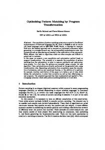
Figure 1. BP pattern and BP model elements. described in Section 4. It compares attributes describing vertices from BP graphs. The necessary notation for representing BP models, BP patterns and their instances as BP graphs is introduced in the next section.
2.2
Business Processes Models and Patterns as BP Graphs
Business Process Patterns and Models
Similar to design patterns in software development, a business process pattern describes a design solution to an operational business problem. The BP pattern provides a common vocabulary and the means to reuse the business process design solution as a building block for more complex processes.
Graphs emerge as a natural representation for processcentric models [5].Graphs can capture both, structure and behavior, and allow abstractions such as BP patterns to be related to process-centric models. Types and labels in graphs can capture the abstract syntax of process modelling languages and the concrete descriptions of process elements, often expressed in natural language.
2.1
2.2.1
Abstraction and BP Patterns
Graph-based BP model
Let M = (VM , EM , TVM , ATVM ) be the graph representing a BP model. M is a finite, undirected, connected, typed and attributed graph. BP model elements and BP connectors are represented by vertices in VM . Edges in EM represent connectivity between vertices in VM . A mapping function TVM : VM → TVM provides types to vertices in VM . The set of types TVM is defined by a classification of BP model elements and it is frequently related to the BP modelling language constructs used to describe the business process. Vertices in VM can have attributes describing it. The function ATVM : TVM → AVM is a mapping function providing attribute vector templates for each type of vertex in TVM . They define what attributes describe a particular type of vertex. The amount of attributes is not restricted, and attributes might also be typed. By composing ATVM and TVM (ATVM ◦ TVM : VM → AVM ) we can obtain the attribute vector ~u describing a particular vertex u ∈ VM . Frequently, a label (name) is a shared attribute among all types of vertices. The label can describe the meaning of the BP element (or BP connector) represented by the vertex, often expressed in natural language. The set of labels for vertices in VM is denoted by LVM . The label of a vertex u ∈ VM is de-
A system can be abstracted by deliberately omitting some details. The choice of the details to omit is made by considering both the intended application of the abstraction and also its users [16]. Generalisation and aggregation are two types of abstraction. They are useful to explain the relation between a BP model and a BP pattern. Aggregation refers to an abstraction in which a relationship between elements is regarded as a higher level element. Generalisation refers to an abstraction in which a set of similar elements is regarded as a generic element [16]. BP Pattern. A BP pattern refers to an aggregation abstraction in which a relationship between generic BP elements and BP connectors is regarded as a higher level BP element. The latter is named BP pattern configuration. Generalisations of BP elements and BP connectors from a BP model are called BP pattern roles and BP pattern connectors, respectively. Fig. 1 illustrates the relations between a BP pattern and a BP model. Generalisation is defined in terms of similarity. Thus, a BP pattern role (BP pattern connector) defines a set of similar BP elements (BP connectors). These BP elements have the same attributes described by the BP pattern role. Similarity between BP elements is 2
noted by `(u), where the mapping function `(·) is the short for ATVM ◦ TVM (·) projected on the label attribute. In a simplified case where ~u has one dimension and it is the vertex label, then ~u = `(u) and M becomes a labelled graph instead an attributed graph. 2.2.2
Graph-based BP pattern configuration
Let P = (VP , EP , TVP , ATVP ) be the graph representing a BP pattern configuration. P is a finite, undirected, connected, typed and attributed graph. BP pattern roles and BP pattern connectors are represented by vertices in P. Edges in P represent connectivity among BP pattern roles and connectors. BP roles and connectors play a central role in describing a BP pattern and consequently both are considered vertices in VP . Analogous to types and attribute vectors for M (a BP model), the mapping function TVP : VP → TVP provides types to vertices in P. TVP defines the set of types of BP pattern roles and BP pattern connectors. The function ATVP : TVP → AVP is the mapping function providing an attribute vector template for each type of vertex in TVP . The composed function ATVP ◦ TVP : VP → AVP provides the attribute vector ~v for each vertex v ∈ VP according to its type. A particular ~v contains the values of the attributes describing the vertex v. The set of labels LVP provide names to BP pattern roles and connectors, often using natural language. Each label (name) is denoted by `(v), with v ∈ VP . 2.2.3
Figure 2. Best practices documentation as BP pattern configurations. [8]. Locally surjective graph homomorphisms can capture the structural relations between a BP pattern configuration and its associated instances in a BP model [10].
3
In this section we introduce a case study based on the National Revenue Agency case defined at SOPOSE085 . We use this case as a running example through the paper. The National Revenue Agency (NRA) is a governmental revenue collection agency which has grown significantly in size and complexity. During its growth, the agency has faced many operational challenges that have triggered rationalization efforts to standardise on emergent processcentric best practices and to reduce operational complexities. The agency has decided to initiate a project to support the spreading and implementation of best practices across the institution. Process-centric best practices are documented as BP patterns and they define an ideal case for processes implementation. BP patterns would lead the definition of new reusable software services. If possible, services would be implemented by exposing functionality of existing software support. The identification of BP pattern instances in the actual NRA’s processes and their associated legacy applications is the starting point of the rationalization effort. The effort attempts to eliminate redundant legacy applications and to enable best practices automation through software services implementation. Fig. 2 illustrates an example of recommended best practices documented as BP pattern configurations. They are described using the BPMN 1.1 notation [1] and they involve the Validate Form, Process Financial Form and Process Non-Financial Form processes. A letter v and number next to each BP pattern role is used as reference through examples in the paper. They are not part of the modelling
Graph-based BP pattern instance
A BP pattern instance Pi is a subgraph in M such that, (1) vertices in Pi ⊆ M maintain a generalisation relation to vertices from the BP pattern configuration P; (2) there exist an edge preserving vertex mapping ϕ : Pi → P that fulfills the properties of a locally surjective homomorphism (see next section for more details). Note that several BP pattern instances in M can exist and, for a single instance Pi , several vertices in Pi can play the role of one vertex in P.
2.3
Case Study
Locally Constrained Homomorphisms
A graph homomorphism is an edge preserving vertex mapping between two graphs. For a vertex u in a graph G = (VG , EG ), the set of all vertices adjacent to u are called the neighbourhood of u. It is denoted by NG (u), with NG (u) = {v|(u, v) = (v, u) ∈ EG }. Locally constrained graph homomorphisms are a special kind of homomorphisms where the image of a vertex’s neighbourhood in a source graph is contained in the neighbourhood of the vertex’s image in the target graph [8], i.e. f (NG (u)) ⊆ NH ( f (u)) holds for every vertex u ∈ VG whenever f : VG → VH is a homomorphism from G to H. For graphs G and H, three kind of homomorphic mappings are locally bijective, injective or surjective homomorphisms
5 http://www.dsl.uow.edu.au/sopose/content/files/main/SOPOSE-CaseStudy.pdf
3
1/p
notation. Consider that the processes from Fig. 3 are the actual NRA’s processes. Processes are described using the BPMN 1.1 notation [1]. A referential letter u and number next to each BP element are used to facilitate explanations through the paper. These references are not part of the BPMN 1.1 notation. This simplified example attempts to illustrate the complexity of processes in organisations. They often involve numerous activities and participants. The greater the number, the more susceptible to errors and increasingly time consuming the analysis tasks became.
sim(~u,~v) = 1 − (|δi · dis(~ui ,~vi )| p ) , 1 ≤ i ≤ |~v| (1) dis(~ui ,~vi ) is the normalised dissimilarity between ~u and ~v in the attribute i. Values of dissimilarity range between 0 and 1, with 0 representing equality. Dissimilarity can become a distance measure, if distance is possible to calculate. According to the nature of each attribute, different measures of dissimilarity (or distance) can be considered. δi is a weighting factor to emphasize or deemphasize the ith attribute value. We assume attributes are independent. p determines the measure’s norm. For p = 2, vertex similarity becomes a measure based on the Euclidean distance.
4
4.2
Vertex Similarity in BP Graphs
One of the most common attributes of BP graph vertices is their labels. Often, labels are sentences in natural language. Few approaches, for instance [2], have considered BP element labels as part of the comparison of BP models. In order to determine if the label of a BP model element refers to a label of a BP pattern role, we calculate their similarity based on the sentence similarity measure described in [12]. This measure is convenient in our context since the elements required to evaluate the measure are dynamically generated using only the information from the words contained in the two labels. The measure considers the semantic similarity among words in the two sentences (labels), which is derived from a Lexical Knowledge Base (LKB) and a corpus, and the word order on the sentence meaning. LKBs are frequently organised as a hierarchy of words defining concepts (for example, WordNet6 or other more specific LKBs targeting particular business domains). Semantic similarity between words is calculated based on the length of the path connecting the words in the hierarchy and their depth in it. By observing the direction (from bottom to top) of the path connecting two words in the hierarchy, it is possible to discriminate between abstraction or refinement of concepts. The latter can be used as indication that a vertex label is an abstraction of another vertex label. We have simplified the explanation of vertex label similarity calculation by avoiding word disambiguation (it requires the analysis of the context where the word appears), abbreviations expansion and acronyms replacement.
Preservation of the structural constraints defined by a BP pattern is one of the aspects that need to be satisfied during the matching of process pattern instances on concrete process models. The latter is captured in our approach by a locally surjective graph homomorphism [10] and it is explained in details in Section 5. However, vertices from a BP pattern maintain an abstraction relation (generalisation) with vertices from its instances. This section describes this generalisation relation in terms of similarity between attributes of BP pattern vertices and attributes of its instances’ vertices. Let P = (VP , EP , TVP , ATVP ) be a BP pattern configuration, M = (VM , EM , TVM , ATVM ) a BP model and Pi a subgraph of M representing an instance of P in M. We say that a BP pattern role v ∈ VP generalise the set Iv ⊆ VM if the similarity between attributes describing each vertex in Iv and attributes describing the BP pattern role v is greater than a threshold ζ~v . This threshold vector is defined within the BP pattern documentation and it is specific to each BP pattern role v from P. The vector ~ζ defines the thresholds for all vertices (BP pattern roles) in VP . The rest of this section explains how similarity between BP graph vertices is calculated.
4.1
Label Similarity
Similarity-Based Attribute Vector
Similarity between two BP graph vertices u and v, the former from a BP pattern configuration P and the latter from a BP model M, is calculated by comparing their attribute vectors ~u and~v. The comparison only concern the attributes describing v. Other attributes in ~u are deliberately omitted since they do not concern the BP pattern configuration P. The choice of the attributes describing a BP pattern is made by considering both its intended application and also its potential users. We assume the existence of a common set of attributes describing vertices from P and M to make possible the comparison (similarity calculation). Similarity between the attribute vectors ~u and ~v is calculated based on the formulation of the weighted Minkowski distance [4] as,
4.2.1
Label Similarity Measure
Similarity between the vertex labels `(u) and `(v), where u is a vertex from a BP model graph M and v is a vertex from a BP pattern configuration P, is derived from the weighted sum of similarities between their associated lexical semantic vectors and word order vectors, simlabel (`(u), `(v)) = ρ · sim(~w(u),~w(v)) + (1 − ρ) · sim(~o(u),~o(v)) 6 Available
4
at http://wordnet.princeton.edu/
(2)
Figure 3. Hypothetical NRA’s processes. The lexical semantic vectors ~w(u) and ~w(v) represent quantifiable values regarding the meaning of words in u and v’s labels. The values are based on information from a lexical knowledge base and corpus. ~o(u) and ~o(v) represent quantifiable values regarding the words’ order in the sentences. ρ determines the relative contributions of the lexical semantic vector similarity and the word order vector similarity measures. If syntax is less relevant, according to [12], a value between 0.5 and 1 should be assigned to ρ. 4.2.2
I(wi (u)) and I(w˜ i (u)) refer to the information content of the words referred by wi (u) and w˜ i (u). The information content of a word is derived from its probability (relative frequency) in a corpus. In order to obtain the value of an entry in (4), we need to calculate the similarity between two words (simW ). We use the word similarity measure from [11]. This measure is a function of the path length connecting the two words in the lexical knowledge base and the depth of their common subsumer. The latter helps to differentiate the similarity between a pair of words referring to more abstract concepts against the similarity between a pair of words referring to more concrete concepts.
Similarity Between Lexical Semantic Vectors
Similarity between the lexical semantic vectors ~w(u) and ~w(v) is defined as the cosine coefficient between them, sim(~w(u),~w(v)) =
~w(u) · ~w(v) k~w(u)kk~w(v)k
4.2.3
Similarity between two word order vectors ~o(u) and ~o(v) associated to the labels `(u) and `(v) is derived from their normalized difference,
(3)
~w(u) and ~w(v) are vectors with m entries. m is the number of words in a joint word set W containing all the different words from the two labels `(u) and `(v), hence m = |W |. Each ith-entry ~wi (u) with i = 1, ..., m is derived from evaluating the similarity between the word from the ith-entry in the joint word set W , annotated wi (u), and the most similar word from the label `(u), annotated w˜ i (u). In turn, the value obtained from the word’s comparison is weighted by the individual information content of the two compared words, ~wi (u) = simW (w˜ i (u), wi (u)) · I(w˜ i (u)) · I(wi (u))
Similarity Between Word Order Vectors
sim(~o(u),~o(v)) = 1 −
k~o(u) −~o(v)k k~o(u) +~o(v)k
(5)
~o(u) and ~o(v) are obtained from the order in which the words in `(u) and `(v) appear. The order is established ~ O ~ defines an order based on a joint word order vector O. for words in the joint word set W used in (3) and (4). ~ the entry associated with that If a word in `(u) is in O, ~ If the word is not in O, ~ word in ~o(u) is its index in O. then two possible entries can be assigned. One is the ~ (only if the similarity index of the most similar word in O
(4) 5
between the compared words is greater than a threshold σO ); otherwise, a value equal to zero is assigned to the entry.
vectors from both BP graphs are compared and matched. Successful individual matches start an expansion stage in a breadth first search manner until obtaining the final BP pattern instances of P in M. After that, a final stage would check if the found BP pattern instances behave as the BP pattern configuration P indicates. This last stage is not described in this paper, but we mentioned here to remind the reader that the behavioral aspect is also important during the BP pattern matching process.
Example 1. Consider the vertex label `(v3 ): Update Client Register from the BP pattern configuration in Fig. 2, and the vertex labels `(u25 ): Update Client Register Document, `(u38 ): Update Customer Register and `(u52 ): Update Client Register from Fig. 3. We want to calculate the similarity between `(v3 ) and the mentioned labels `(u25 ), `(u38 ) and `(u52 ). The associated joint word sets are W(v3 ,u25 ) = {Update Client Register Document}, W(v3 ,u38 ) = {Update Client Register Customer}, W(v3 ,u52 ) = {Update Client Register} The lexical semantic vectors associated to each joint word set are shown below. W(v3 ,u25 ) : ~w(v3 ) = [1 1 1 0], ~w(u25 ) = [1 1 1 1] W(v3 ,u38 ) : ~w(v3 ) = [1 1 1 0.8182], ~w(u38 ) = [1 0.8182 1 1] W(v3 ,u52 ) : ~w(v3 ) = [1 1 1], ~w(u52 ) = [1 1 1] In order to calculate these values, we used the WordNet::Similarity service7 to obtain the path length between the compared words and depth of the common subsumer, and replace those in 5. Word order vectors were obtained as the following example. Consider the joint word set W(v3 ,u38 ) = {Update Client Register Customer} and its associated joint word order vec~ (v ,u ) = [1 2 3 4]. The word order vector for v3 is tor O 3 38 ~o(v3 ) = [1 2 3 2]. The first three entries in ~o(v3 ) relates to words in `(v3 ), the last entry (associated to the word Customer) is not in `(v3 ), but the most similar word is Client, and consequently the last entry in ~o(v3 ) is the index of ~ Analogously for u38 , ~o(u38 ) = [1 4 3 4]. After Client in O. calculating the lexical semantic vector similarities and word order vector similarities, we calculated the label similarity between `(v3 ) from the BP pattern (Validate Form) in Fig. 2 and each of the ’matched’ labels associated with vertices in the BP model from Fig. 3 according to (2). We have considered ρ = 0.85, following the experimental findings in [12]. Thus, simlabel (`(v3 ), `(u25 )) = 0.8154, simlabel (`(v3 ), `(u38 )) = 0.9523, and simlabel (`(v3 ), `(u25 )) = 1.0000.
5
5.1
The main stages of our proposed BP pattern matching technique are depicted in Fig. 4. It is based on our previous algorithm for structural pattern matching [10], here augmented with type and attribute vertex matching. Stage 1. The algorithm starts comparing vertices types in VM against vertices types in VP . The set Ftype (VM ) is obtained at the end of this stage and it contains all the vertices in VM which have the same or more refined types than types vertices in VP . Stage 2. In this stage the algorithm only processes vertices from the set Ftype (VM ). It measures the similarity between each attribute vector ~u ∈ AFtype (VM ) from the BP model and each attribute vector ~v ∈ AVP from the BP pattern, such that types of ~u and ~v were previously matched. The result is the set Fattr (Ftype (VM )). This set contains vertices in VM whose types were matched with types vertices in VP and their associated attribute vectors maintain a generalisation relation with vertices in VP . Stage 3. If the similarity between the attribute vectors ~u and ~v as defined in (1) surpass the threshold defined by ζ~v (see Section 4), the vertex u is kept within the set of individual temporal BP pattern instances and it is renamed as tPu , referring to a subgraph in M which is a temporal match of P centered in u. ζ~v indicates (quantitatively) how similar a BP pattern role v and its instances should be. Similarity is calculated only for the attributes describing the pattern. Other attributes describing BP pattern role instances are omitted. At this moment, the set T Pu constitutes the set of individual tPu that the algorithm will continue processing. Stage 4. During this stage, each temporal match tPu constituted by one vertex is expanded with all its neighbors which also are in T Pu and satisfies gen(NT Pu (tPu )) = NP (gen(tPu )). The latter condition refers to a Locally Surjective Graph Homomorphism - LSGH, and it should be satisfied (at least partially) between the subgraph formed by tPu and its neighbours, and the graph P. A partial LSGH indicates that not all vertices in VP have been mapped by gen. This partial mapping is incrementally completed while the algorithm expands the initial temporal matches in T Pu . Final matches that can not be further expanded can also be partial (not complete). The reader can review about exact,
BP Pattern Matching
This section describes the main steps of our technique for matching BP pattern instances in BP models. The technique is based on an algorithm that combines structural graph matching with vertex type and vertex attributes similarities calculation. Consider M = (VM , EM , TVM , ATVM ) be the graph representing a BP model and P = (VP , EP , TVP , ATVP ) be the graph representing a BP pattern configuration. In order to match instances of P in M, firstly, vertices types and attributes 7 Available
Main Stages of BP Pattern Matching
at http://wn-similarity.sourceforge.net/
6
vertex label similarity as in (2). All vertices from the BP model graph whose label similarity values to labels from vertices in the BP pattern graphs are greater than a threshold ~ζ (0.75 for each entry in this example) are considered initial BP pattern matches. Elements in the BP Model highlighted in light grey and dark grey are initial matched vertices (See Fig. 3). Subsequent iterations expanded the unitary matches by adding all BP elements (vertices and edges) such that structural relations from the BP patterns and the BP model satisfied a locally surjective homomorphism. An ideal case for a match is an exact match. For example, the BP pattern instance in Fig. 3 encompassing the vertices u51 to u55 and their respective edges (highlighted in dark grey colour) is an exact match of the BP pattern Process Form from Fig. 2. Instead, the rest of highlighted vertices correspond to partial and sequentially overlapped instances of the Validate Form and Process Form BP patterns. The vertex u12 ; the subgraph formed by u25 , u26 and their connection; and u38 are partial matches of Process Form (all of them in dark grey colour). These partial matches are sequentially overlapped with partial instances of Validate Form. If we allow inexact matches as defined in [10], a single match could include intermediate elements that do not change the intention of the BP pattern. For example, all elements in light grey colour from Fig. 3 and the intermediate elements u13 to u17 , u30 to u32 , u42 to u44 , u49 and edges connecting them would form an inexact match (inexact BP pattern instance) of Validate Form.
Figure 4. Main steps of BP pattern matching. partial and inexact matching in [10]. Each of the following repetitions at this stage incorporate new neighbours to each tPu . After the first iteration, most tPu would not be constituted by a single vertex anymore. Iteration by iteration temporal BP pattern matches (tPu ) are expanded in M. The algorithm terminates when no more expansion steps can be done, i.e. it is not possible to establish more connections between vertices in T Pu according to constraints imposed by a LSGH from tPu to P. The results of this stage are: (1) a set of subgraphs {Pu }, where each subgraph Pu in {Pu } is a product of the expansion of one tPu in T Pu ; (2) an individual score matrix Scmatching (Pu ) providing information about a particular instance Pu of P; and (3) a global score matrix Scmatching associated to M describing the level of instantiation of P in M. Note that several exact or partial instances of P in M might exist. If different pattern instances share edges in M, we say that there are overlaps of the pattern P in M. The algorithm identifies the connected subgraphs in M containing overlaps as one single subgraph.
6
Related Work
Recent contributions providing solutions to compare and query business process models [2],[3],[15] expose the potential and some problems regarding the implementation of an automated BP pattern matching mechanism. BPMN-Q [2] and BP-QL [3] are two approaches for querying processcentric models. Resembling keyword-based queries in a search engine, queries in BPMN-Q and BP-QL are formulated as graphically represented processes. While BPMNQ considers semantic processing of process element labels, BP-QL focused on simulated behaviour. Unfortunately, both approaches uses a trace-simulation notion when comparing processes. This could lead to performance problems when a query is processed on a large and complex process model with numerous branching conditions. We have tried to avoid this problem by exploring the target process model in a breadth first search manner instead of using a depth first search strategy. In [15], the authors provide a solution to check conformance of a process model and an event log. Control flow semantics and observed behavior are the main aspects analysed. Semantics associated with activities’ descriptions or passing data is not considered.
Example 2. Consider the BP pattern configuration from Fig. 2 (Best practices for Validate Form and Process Form). We are interested in knowing where these BP patterns are instantiated on the NRA’s processes from Fig. 3. Using the mechanism explained in Section 5.1 we start matching vertices from the BP pattern graphs in Fig. 2 against vertices from the BP model graph in 3. In this example we only considers the label attribute when calculating the similarity between attribute vectors, i.e we only calculate the 7
Matching BP patterns for recommending the scope and granularity of services follows a top-down approach for designing services. SOA modelling frameworks and traceability support, such as [17] and [9], provide a medium to enhance service design based on BP pattern matching with analysis of existing software support. Traceability in this context refers to trace links relating BP models to enterprise IT architecture documentation. Several BP pattern instances relating to a single candidate service might be traced to redundant software support. This information is critical during (existing software) rationalisation efforts and SOA migration. Moreover, different BP pattern instances can indicate service variation points. The latter can complement approaches focused on variation-oriented mechanisms such as [13]. If BP patterns are used to define best practices or process regulations, a derived advantage is that the new pattern-based services would be closer to comply with regulatory constraints and to adhere to standards [6].
7
tant concepts to develop enterprise service-based systems of improved quality.
References [1] Business process modeling notation (BPMN) version 1.1. OMG, 2008. [2] A. Awad, A. Polyvyanyy, and M. Weske. Semantic querying of business process models. In EDOC’08, pages 85–94. IEEE, 2008. [3] C. Beeri, A. Eyal, S. Kamenkovich, and T. Milo. Querying business processes with BP-QL. Information Systems, 33(6):477–507, 2008. [4] S.-H. Cha. Comprehensive survey on distance/similarity measures between probability density functions. Int. J. MMMAS, 1(4):300–307, 2007. [5] H. Ehrig, G. Engels, H.-J. Kreowski, and G. Rozenberg, editors. Handbook of Graph Grammars and Computing by Graph Transformation, vol. 2. World Scientific, 1999. [6] M. El Kharbili, A. de Medeiros, S. Stein, and W. M. van der Aalst. Business process compliance checking: Current state and future challenges. In MobIs’08, volume 141 of LNI, pages 107–113. GI, 2008. [7] T. Erl. Service-oriented architecture: Concepts, Technology, and Design. Prentice Hall, 2004. [8] J. Fiala and J. Kratochvil. Locally constrained graph homomorphisms–structure, complexity, and applications. Computer Science Review, 2(2):97–111, 2008. [9] V. Gacitua-Decar and C. Pahl. Service architecture design for e-businesses: A pattern-based approach. In EC-WEB’08, volume 5183 of LNCS, pages 41–50. Springer, 2008. [10] V. Gacitua-Decar and C. Pahl. Towards reuse of business processes patterns to design services. In W. Binder and S. Dustdar, editors, Emerging Web Services Technology, volume III. Birkhauser Basel, 2009 (to appear). [11] Y. Li, Z. A. Bandar, and D. McLean. An approach for measuring semantic similarity between words using multiple information sources. IEEE Trans. on KDE, 15(4):871–882, 2003. [12] Y. Li, D. McLean, Z. A. Bandar, J. D. O’Shea, and K. Crockett. Sentence similarity based on semantic nets and corpus statistics. IEEE Trans. on KDE, 18(8):1138–1150, 2006. [13] N. C. Narendra, K. Ponnalagu, B. Srivastava, and G. S. Banavar. Variation-oriented engineering (VOE): Enhancing reusability of soa-based solutions. In SCC’08, volume 1, pages 257–264. IEEE, 2008. [14] M. P. Papazoglou and W. J. van den Heuvel. Serviceoriented design and development methodology. IJWET, 2:412 – 442, 2006. [15] A. Rozinat and W. van der Aalst. Conformance checking of processes based on monitoring real behavior. Inf. Syst., 33(1):64–95, 2008. [16] J. M. Smith and D. C. P. Smith. Database abstractions: aggregation and generalization. TODS, 2(2):105–133, 1977. [17] L. J. Zhang, N. Zhou, Y. M. Chee, A. Jalaldeen, K. Ponnalagu, R. R. Sindhgatta, A. Arsanjani, and F. Bernardini. SOMA-ME: a platform for the model-driven design of soa solutions. IBM Syst. J., 47(3):397–413, 2008.
Conclusion
Following the successful experience of using design patterns as a medium to reuse proven and accepted solutions to develop software, we have proposed to extend this idea to BP patterns and their use during the development of process-centric service-based systems. BP patterns promote the reuse of expert design knowledge. An automatic mechanism to match BP pattern instances in process models can save time and reduce involuntary human errors during the design of BP pattern-based enterprise services. In this paper we have presented a solution for automatic BP pattern matching. BP patterns and BP models are represented as graphs. Graph vertices represent process elements and their connectivity. The BP pattern matching solution is a graph based algorithm enhanced with type and attribute vertex matching - highly focused on semantics. A measure to calculate vertex attribute similarity is the base to distinguish BP pattern role instances. We have used through the paper a case based on the NRA’s case study proposed at SOPOSE08 to explain our approach. After BP patterns are matched, we expect that the identified BP pattern instances behave as their associated pattern definition. We are currently working on defining an appropriate and efficient manner to perform this verification. Moreover, an appropriate evaluation considering the judgment of people involved in process- and service- modelling tasks is being prepared. Process centric development of enterprise services bring to the table numerous challenges. We have addressed some aspects related to process abstraction and structural and semantic analysis of processes. Our objective is to promote automation and process design reuse by means of BP patterns. We believe that automation and reuse are two impor8