International Journal of Automotive Technology, Vol. 13, No. 4, pp. 645−651 (2012) DOI 10.1007/s12239−012−0063−y
Copyright © 2012 KSAE/ 065−14 pISSN 1229−9138/ eISSN 1976-3832
AUTOMATIC CONTROL OF CLUTCHES AND SIMULATIONS FOR PARALLEL HYBRID VEHICLES V. T. MINH* and A. A. RASHID Mechanical Engineering Department, Universiti Teknologi PETRONAS, Tronoh 31750, Malaysia (Received 9 June 2011; Revised 19 September 2011; Accepted 17 October 2011) ABSTRACT−This paper is a continuation of a previous paper titled “Modeling and Model Predictive Control for Hybrid Vehicle” published on IJAT/2011 describing a mathematical model and design for a model predictive controller for tracking speeds and simulations. The present paper further describes a fuzzy logic controller for the smooth and quick engagement of an automatic clutch. The described controller uses both fuzzy logic and slip control algorithms to enable automatic clutch engagement. Clutch engagement and comprehensive simulations for the hybrid vehicle are conducted in MATLAB R2009s. The research described herein offers theoretical solutions for how to better control clutch slip and engagement within realistic parameters used for hybrid vehicles. Algorithms and operations of this fuzzy logic controller can be implemented in electronic control units for automatic clutch engagements and gear-shifting processes. KEY WORDS : Parallel hybrid electrical vehicle, Clutch engagement, Slip control
1. INTRODUCTION
must be factored into an overall cost analysis. It is also important for the dynamic clutch engagements between ICE and EM to be controlled rapidly and as smoothly as possible. For comfort and safety reasons, several control approaches for smothering the engagement of clutches have been developed, including backstepping control (Kim et al., 2009), optimal control (Paganelli et al., 2002) and model predictive control (Sciarretta et al., 2004). In this research, new real-time fuzzy logic schemes are developed to control the automatic friction clutch and are applied to clutch engagement. The objective of this application is to improve both the energy efficiency and the driving experience of parallel hybrid electric vehicles (HEVs). There have been a number of publications related to the automatic control of clutch in vehicle: An automatic transmission with a dry clutch designed to improve efficiency is described in (Kluger and Long, 1999); Zero shift technology for very fast gear transmissions with a seamless automated manual transmission has been studied in (Heath and Child, 2007); A design of optimal friction clutch controller for commercial trucks based on linear quadratic regulator techniques has been discussed in (David and Natarajang, 2005); The flatness-based clutch control for automated manual transmissions with electrohydraulic clutch has been considered in (Horn et al., 2003); And, a fuzzy neural network control of an automatic mechanical transmission clutch during the starting phase has been reported in (Ran and Dongye, 2008). In this study, we will develop fuzzy logic control algorithms for an automatic friction clutch for use in in HEVs. The described system relies on fuzzy logic control to
In parallel hybrid electric vehicles, two separate power sources are independently installed in a manner that allows both power sources to propel the vehicle independently or concurrently. Most commonly, the internal combustion engine (ICE), electric motor (EM) and gearbox are coupled by automatically controlled clutches or via planetary gears. When the vehicle is operating at low speeds, the clutch between the ICE and the EM is open, and the EM is able to propel the vehicle by itself. At high speeds, the clutch is closed; the ICE is activated and propels the vehicle while the EM is turned off or while it runs as a generator to recharge the battery. At very high speeds or in crucial heavy loads, the EM can be turned on automatically to supplement the ICE in propelling the vehicle. More information regarding parallel hybrid vehicles can be found in the literature (Langari and Won, 2003; Lukic and Emadi, 2004). Existing methods of controlling the transition between EM- and ICE-based propulsion are based on heuristic knowledge of the behavior of the ICEs and EMs, where fuzzy logic schemes (Schouten et al., 2002) are typical. These control methods were developed for use in the early hybrid implementations. However, they did not fully exploit the system’s potential fuel optimization because the electrical energy and the fuel energy produced were not directly comparable. The main goal of hybrid control is the minimization of fuel consumption; any efficiencies gained *Corresponding author. e-mail:
[email protected]. my 645
646
V. T. MINH and A. A. RASHID
create an intelligent controller that can use uncertain and imprecise information. The use of fuzzy logic can help circumvent the need for rigorous mathematical modeling. In the automotive industry, we have seen the successful application of fuzzy logic to control the anti-lock braking system (ABS). Most ABSs use a 16-bit microcontroller that can compute a medium-size fuzzy logic system in 0.5 milliseconds, using only 2 kB of ROM space. The control closed-loop time is approximately 5 milliseconds. Within this time interval, the microcontrollers must fetch all the sensor data, preprocess it, compute the ABS algorithms, drive the bypass valves for the brake fluid, and successfully conduct the brake activities. The main requirement for an automated clutch slip controller is to enable smooth and quick transitions between pure electrical driving at low speeds (below 50 km/h) and hybrid driving at high speeds (above 50 km/h) without an interruption of demanded driving power and jerk. Mathematical models for clutch systems are always available, but the interaction of a clutch system with the driver and all other driving conditions is too complex to adequately model. The use of fuzzy logic can lead to an efficient technique with higher computational efficiency than other conventional control techniques. This paper is organized as follows: In section 2, a typical parallel HEV and clutch engagement modeling is formulated; In section 3, clutch fuzzy logic control algorithms are developed and tested, and their performance is compared to that of the torque converter; In section 4, comprehensive HEV simulations are conducted to illustrate the performances of this control model for the automatic friction clutch; and Finally, section 5 presents the conclusions.
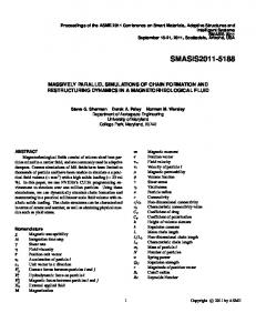
2. HEV AND CLUTCH ENGAGEMENT MODELING Figure 1 shows the configuration of a common parallel HEV, consisting of a conventional ICE and two EMs (i.e., EM1 and EM2). An automatically-controlled clutch separates the drivetrain into two parts: Part 1: ICE with EM1; and Part 2: EM2 and the rest of the transmission. EM1 serves as a starter and a generator. This rear wheeldriven vehicle is equipped with a standard automated gearbox without a torque converter. During pure electrical driving at low speeds (less than 50
Figure 1. Configuration of parallel hybrid powertrain.
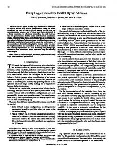
km/h), the clutch is opened and a series hybrid configuration is achieved. In this operating range, the second DC motor (EM2) propels the vehicle. The transmission from series mode to parallel mode takes place at high speeds (more than 50 km/h) by closing the clutch. The first DC motor (EM1) activates the ICE to run the vehicle, while the EM2 shuts off. EM1 then acts as a generator to recharge the battery. During some critical operations, e.g., in response to demands of the driver, during some essential heavy loads, or other emergency cases if needed, both EM1 and EM2 are be automatically turned on simultaneously to assist the ICE in propelling the vehicle. The clutch is one of the most important components in the vehicle drivetrain. A clutch allows the connection and transmission of driving force from the ICE or EM1 and EM2 to the wheels. The clutch system for this model consists of two friction disks connected at the ends of two rotating shafts (see figure 2). One shaft is attached to the ICEs or EMs (the power unit or the driving member). The other shaft (the wheels or driven member) is connected to the gearbox and the differential gearbox to transmit the power to run the vehicle. The clutch connection has two separate modes of configuration: engaged (locked together and rotating at the same angular speed), or disengaged (decoupled and rotating in at different angular speed). Modeling the transmission between the two modes is a challenge: As the system loses one degree of freedom in the locking up process, the torque during this process becomes a discontinuity. The magnitude of this torque falls from the maximum threshold to a low value necessary to keep the two disks of the clutch spinning at the same speed. The two dynamic models are used to simulate the locked mode (engaged) and the decoupled mode (disengaged). A switching mechanism is developed to recognize the precise moments to transition between the two modes and activate the switches accordingly. Figure 2 shows a clutch system, where M1 is the driving torque (input); FNC is the normal force between friction disks; J1 and J2 are moments of inertia; kβ1 and kβ2 are the damping coefficients in two shafts; µk and µs are kinetic and static coefficients of friction; ω1 and ω2 are angular velocities of the two shafts; rI and rO are the inner and outer radii, respectively, of the clutch friction surfaces; Rc is the
Figure 2. Clutch system.
AUTOMATIC CONTROL OF CLUTCHES AND SIMULATIONS FOR PARALLEL HYBRID VEHICLES
clutch equivalent net radius; M2 is the torque transmitted through the clutch; and MR is the torque required for maintaining the locked position. The dynamic equations for the locked mode are derived as follows: J1ω 1 = M1 – kβ1 ω 1 – M2
(1)
J2ω· 2 = M2 – ω 2 kβ2
The full torque capacity in a clutch is a function of its area (AC), friction force (Ff), and the corresponding radii (r, rO and rI): Tfmax =
r
Ff
- ∂A , or ∫ ∫ ----A
647
A switching diagram for the clutch activities is illustrated in Figure 3. In this clutch model, rapid changes in engine speed lead to the rapid changes in acceleration and jerk of the vehicle. The engine speed undegoes a rapid change of acceleration as it synchronizes with the drivetrain via the clutch engagement rate. For a low jerk property, it would be advantageous to prolong engagement time and to avoid any sudden step input to the clutch. This is impractical in reality as excessive slipping overheats the clutch and reduces operating life. Ideally, any engagement should not last any more than 3 to 4 seconds. In the next section, we will consider the application of fuzzy logic algorithms to control the clutch engagement.
C
Ac
C
FNC µ - rO 2π 2 Tfmax = -------------------r ∂r∂θ, or π ( r2O – r2I ) ∫rI ∫0
3. CLUTCH FUZZY LOGIC CONTROLLER ALGORITHMS (2)
( r3O – r3I ) 2 Tfmax = --- RC FN µ with Rc = ----------------3 ( r2O – r2I )
When the clutch slips, the model uses the kinetic friction coefficient (µK): 2 = sgn ( ω 1 – ω 2 )Tfmax = sgn ( ω 1 – ω 2 ) --- RC FNC µK TSlipping 2 3
(3)
When the clutch locks, i.e., when, ω1 = ω2 = ω, the system acts as single unit, and equation (1) can be combined into a single equation for this locked mode: ( J1 + J2 )ω = M1 – ( kβ1 + kβ2 )ω ,
(4)
or J2M1 – ( J2Mβ1 – J1Mβ2 )ω MLocked = Mf = ------------------------------------------------------2 J2 + J 1
(5)
The clutch remains locked until the magnitude of the friction torque (Mf) exceeds the static friction capacity ( MStatic fmax ): 2MStatic R F µ fmax = -3 C NC S
Figure 3. Friction mode transmissions.
(6)
Automatic control of clutches for vehicle starting and smooth gear shifting is becoming an important issue in automotive engineering. Currently, the automatic transmission is still based on torque converters with hydraulic systems; driver comfort is improved by eliminating the clutch pedal, and the driver has only two pedals to operate (accelerator and brake). However, torque converters usually offer a lower efficiency of transmission due to energy losses by the hydraulic pumps and the higher slip ratio between input and output. The energy loss in the torque converter warms the transmission fluid instead of providing torque to the wheels. The efficiency of a torque converter is approximately 86%; in comparison, a dry clutch can offer an efficiency of 97% (Kluger and Long, 1999). Because the dry clutch is always the most efficient transmission available, this paper develops an automatic controller for a dry clutch with a higher efficiency of transmission at a lower price compared to torque converters. The new system also achieves greater noise and vibration reduction and increased clutch life because clutch slip is always tightly controlled for optimal torque transmission efficiency. An automatic controller for clutches must be designed to perform in two operating modes: shifting connections and changing gears. Shifting connection is the mode of clutch engagement or disengagement that depends on the driver’s intent, as indicated by activation of the engine throttle. The controller will determine the shifting connection mode via the position and the rate of throttle operation. The changing gear mode is selected based on the current torque load and the vehicle velocity matching with the engine speed. Based on the requirements of the two clutch operating modes, a control method is selected with the use of a slipfeedback regulator. This method uses the difference between the input speeds and output speeds of the clutch to create a feedback loop to control the engagement pressure. The slip is simply the speed difference between the input and the output shafts of the clutch and finally reaching zero
648
V. T. MINH and A. A. RASHID
when the clutch is locked. The clutch engagement pressure will be regulated in proportion to the slip rate with special notions on this clutch lockup and the idling engine speed. Fuzzy logic algorithms have been developed to enable the automatic clutch to understand driver intention. For example, an aggressive pressure on the accelerator pedal or a rapid throttle opening rate can be interpreted to mean that the driver needs a high pressure ramp rate on the clutch engagement for a short time. In contrast, a gradual pressure on the accelerator pedal will lead to a long and smooth clutch engagement period. A fast release of the accelerator pedal leads to a rapid drop in engine speed and a rapid reduction in clutch pressure. Thus, the clutch is disengaged with negative pressure gain and the engine runs in idling condition. The gear shifting operations are activated accordingly based on output torque load and vehicle velocity. Fuzzy logic rules have been developed using variables for throttle position, e.g., Closed (< 1%), Narrow (1-25%), Normal ( 25-85%), and Wide (85-100%); rate, e.g., Low (85%/s); engine speed, e.g., Very Low (3500 rpm); and engine speed rate, e.g., Dropping Quickly (3000 rpm/s). A fuzzy clutch controller is designed where the clutch pressure is a function of the slip, slip gain, and fuzzy logic rules. Variables for the slip gain of this controller are as follows: Negative (