World Electric Vehicle Journal Vol. 6 - ISSN 2032-6653 - © 2013 WEVA Page
Page 0283
EVS27 Barcelona, Spain, November 17-20, 2013
Development of Engine Clutch Control for Parallel Hybrid Vehicles Joonyoung Park1 1
Hyundai Motor Company, 772-1, Jangduk, Hwaseong, Gyeonggi, 445-706, Korea,
[email protected]
Abstract The parallel hybrid configuration in which a clutch is installed between an engine and a motor can shift its operation mode between pure electric and hybrid vehicle mode by engaging or disengaging the clutch. To enhance drivability of the system in shifting its operation mode, it is required to prepare appropriate measures to control the clutch in response to driving conditions. This paper introduces the hydraulic clutch control strategy which is composed of a synchronized engaging and a launch slip engaging maneuver. The strategy also covers the criteria to decide the proper engaging method between above two candidates for current circumstance. This study also deals with the learning algorithm to compensate the variations of the clutch hardware and to realize consistent drivability across all units. The learning algorithm utilizes the traction motor and a pressure sensor to identify the all the variation terms of the clutch with the required level of accuracy. Keywords: parallel HEV, powertrain, control system
1
Introduction
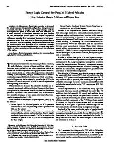
Hyundai launched the hybrid version of its middle size passenger car, ‘Sonata HEV’ in 2011 and it has released 2013 model year of the HEV which has been improved in terms of capabilities of electric drive units and clutch control. The HEV employs the parallel hybrid configuration in which the hydraulic clutch and the traction motor implemented between the internal combustion engine and the automatic transmission as shown in Fig. 1. The torque converter of the transmission is also eliminated to improve the power transmission efficiency and the alternator and start motor for the engine is replace with the integrated starter generator (ISG) which is coupled with the high voltage main battery through the inverter. This hybrid system is capable of realizing several operation modes to improve its fuel efficiency as
represented in Fig. 2. In low load and low speed driving condition, the HEV is operated in the pure electric vehicle mode in which the engine is turned off and the clutch is disengaged. The HEV also increases the regenerative braking energy by disengaging the clutch and eliminating the engine drag from the driveline. When the driver’s torque demand and the vehicle speed are increased, the parallel hybrid mode is activated to blend the fuel power and electric power by turning on the engine and engaging the clutch. On the other hand, on low speed and high load driving condition in which the clutch cannot be engaged due to the engine speed constraint, the series hybrid mode is realized and the engine power can be supplied to the motor electrically. However, when the driver’s power demand exceeds power limitation of the ISG and the motor represented in table 1, it is required to transfer the engine power through the clutch slip. This study introduces the clutch control strategy to
EVS27 International Battery, Hybrid and Fuel Cell Electric Vehicle Symposium
1
World Electric Vehicle Journal Vol. 6 - ISSN 2032-6653 - © 2013 WEVA Page
shift the operation mode of the HEV properly in terms of drivability and fuel efficiency according to the driving condition. The strategy also includes the learning algorithm which assures the consistent drivability by compensating the clutch hardware variations which are induced by manufacturing tolerance and aging[1].
synchronizing engagement and the launch slip engagement. To determine the proper method in engaging the clutch, we need to consider various states of the system and driving conditions such as the driver’s torque demand, state of charge (SOC) of the main battery and the gradient of the road.
2.1 Electrical Path Mechanical Path +
-
Battery
ISG
Inverter
Belt Motor
Automatic Transmission
FD
Internal Combustion Clutch Engine
Figure1: Parallel HEV configuration
Figure2: Operation modes
Table1: Specification of hybrid powertrain
Engine
Motor ISG Battery Transmission
2
Type Displacement Max. power Max. torque Max. power Max. torque Max. power Max. torque Type Capacity Type
4 cylinder MPI 2.4 Liter 124 kW 203 Nm 35 kW 205 Nm 8 kW 43 Nm LiPb 5.3 Ah 6 speed automatic
Clutch engagement control
The maneuvers to engage the clutch can be roughly classified into 2 methods, the
Page 0284
Synchronization engagement
The first maneuver, the synchronized engaging method needs the procedure to make the engine and the motor revolve at the same angular speed before the clutch is engaged. The motor fulfills the driver torque demand while the speed of the clutch input is controlled using the torque from the engine and the ISG to reach the speed of the clutch output. When the synchronization between the both sides of the clutch is established, the clutch can be locked up without observable slip by increasing the pressure of the hydraulic clutch system. Then the demand power is distributed to the engine and the motor by increasing the engine torque and decreasing the motor torque gradually. The overall procedure of the synchronization engagement is represented on Fig. 3. This method is usually preferred since it has advantages in terms of the clutch endurance and drivability over the other method accompanied by clutch slip. In this method, the vehicle needs to be accelerated only by the motor and the speed of the clutch output needs to be increased up to the minimum engine speed where the synchronization is feasible. In most cases, the motor is capable of accelerating the vehicle up to the synchronization speed to engage the clutch. However, there are several cases in which the synchronized engaging is not feasible such as launching the vehicle on a steep slope or driving the motor with a depleted battery.
2.2
Launch slip engagement
The other engaging method, the launch slip is prepared to cover the circumstance in which the output side of the clutch cannot reach the minimum engine speed with the motor power and the synchronization between both sides of the clutch cannot be established[2]. The motor is not capable of accelerating the vehicle and increasing the speed of the clutch output side when the external load is greater than the maximum torque of the motor like when the vehicle is climbing a steep slope. So the engine torque needs to be transferred to the drive wheels through the clutch slip to realize more propulsion torque. As shown in Fig. 4, the blending of the engine torque and the
EVS27 International Battery, Hybrid and Fuel Cell Electric Vehicle Symposium
2
World Electric Vehicle Journal Vol. 6 - ISSN 2032-6653 - © 2013 WEVA Page
motor torque is proceeding in the slip phase of the clutch. To maintain the engine speed in proper range, the engine needs to compensate the clutch load which is generated by increasing the pressure of the hydraulic clutch. On the other hands, to meet the driver’s torque demand, the motor needs to fill out the difference between the torque demand and the clutch slip torque exactly. So it is essential to identify the exact clutch torque for the stability of the engine speed and for satisfying the driver’s torque demand without hindering drivability (Fig. 5).
Figure5: Control scheme of the launch slip engagement
2.3
Figure3: Concept of the synchronization engagement
Page 0285
Decision of engagement method
To make a proper decision in selecting the clutch control method among the synchronization engagement and the launch slip engagement, it is required to examine various state information including torque, speed and SOC, When the motor speed is greater than the minimum engine speed, it is obvious that the synchronization engagement is a proper solution in terms of drivability and endurance of the clutch system. In the opposite case, however, we need to prepare more complicated criteria as summarized in Fig. 6. If the driver’s torque demand exceeds the maximum available torque of the motor, it is adequate to start the slip control immediately to deliver the engine torque to the wheels. On the other hand, if the overall system demand power including auxiliary system loads is so small that it can be compensated by the generated power using the ISG, the clutch engagement is not necessary and the series driving mode is activated. For the rest area of the criteria, the acceleration of vehicle, clutch temperature and SOC is important properties for the decision. If the acceleration rate is above a certain threshold and the speed of the clutch output seems to be accelerated up to the synchronization speed in a few seconds, the synchronization engagement would be more proper solution. Otherwise, we need to trade off between the clutch temperature and the SOC. Continuous slip control could result an overheated clutch and continuous waiting state for the synchronization could lead to having a depleted battery.
3
Clutch variation learning
Figure 7 represents the typical relation between the current of the solenoid and the torque transfer of the hydraulic clutch. In practice, the relation is distorted by the variation of the clutch system which is induced by aging and manufacturing tolerance. Figure4: Concept of the launch slip engagement
EVS27 International Battery, Hybrid and Fuel Cell Electric Vehicle Symposium
3
World Electric Vehicle Journal Vol. 6 - ISSN 2032-6653 - © 2013 WEVA Page
The clutch variation can be classified into offset, gain and linearity term. If the offset variation is increased in the engine clutch of the parallel HEV, it is not feasible to estimate the moment at which the clutch torque is transferred. Therefore, the clutch torque cannot be compensated by the motor torque at the appropriate moment and jerk can be caused by the discrepancy. Since the error induced by the gain variation increases as the solenoid current increases, the gain variation affects the stability of the engine speed control on heavy slip condition more seriously. Lastly, the linearity variation impedes the drivability of acceleration by obstructing the desirable increasing rate of the clutch torque transfer. So, this study suggests the clutch learning strategy to ensure the precision control required by the HEV system. The proposed learning method utilizes the traction motor of the HEV and the pressure sensor commonly used in conventional automatic transmissions to get the required level of precision.
Figure7: Clutch hardware variations
3.1
Offset variation learning
The offset variation distorts the solenoid current value corresponding to the touch point at which contact of the friction plates is made and torque starts to be transferred[3]. The offset variation is mainly induced by wear of friction plates and assembly tolerance. Generally, the touch point has been sensed by observing the engine torque or speed change while vehicle is in coasting state and the clutch pressure is increasing. However, the method has disadvantage in terms of precision due to engine torque uncertainty and external disturbances. This study suggests a new learning method which minimizes the effect of the external variations and is only available in the HEV. As shown in Fig. 8, this method increases the solenoid current value in stepwise until the motor speed or torque is changed while the engine and the motor are controlled to be maintained at different revolution speed in neutral or parking state of the transmission. Since
Page 0286
the motor speed controller increases or decreases the control output based on the speed error, it can detect whether the external load of the clutch is engaged with precision of the motor torque resolution.
Figure8: Offset learning procedure
3.2
Gain variation learning
The gain variation refers to the difference in the ratio between increasing rate of torque and solenoid current. This variation term is mostly influenced by the friction coefficient of the plates and the return spring coefficient. The gain variation can be estimated by comparing ideal clutch torque and actual clutch torque when sufficient current value above the touch point is applied (Fig. 9). The ideal clutch torque can be calculated using a coulomb friction model with clutch hardware parameters. The actual clutch torque can be estimated using the motor in neutral or parking state of the transmission. Since the motor is controlled at a constant speed, the speed feedback controller outputs compensation torque for the clutch load and the compensation torque can be regarded as the actual clutch torque in steady state. Because gain variation learning method measures the actual torque using the motor, the degree of precision is depend on the accuracy of the motor torque.
Figure9: Gain learning procedure
EVS27 International Battery, Hybrid and Fuel Cell Electric Vehicle Symposium
4
World Electric Vehicle Journal Vol. 6 - ISSN 2032-6653 - © 2013 WEVA Page
3.3
Linearity variation learning
Pressure
Lastly, the linearity variation represents the difference of non-linearity in the current-torque relation. Linearity variation is mostly induced by the non-linearity characteristics of the solenoid valve. Having linearity variation means that the clutch torque is increased nonlinearly with respect to the solenoid current and the nonlinearity differs from unit to unit. Though the current and torque relation at both ends of the clutch torque control range is drawn by the offset and gain learning methods described above, nonlinearity and its variation make it difficult to infer the relation for the range between the two ends. If the gain learning is performed for several points within the clutch control range, the linearity characteristics can be identified. However, this idea is not practical since it requires too much time and may bring clutch durability problems. In this study, the pressure sensor based linearity compensation is proposed. In the circumstance where the engine and the motor stay in the same revolution speed such as vehicle’s standstill condition, it is possible to increase the solenoid current without any influence to drivability. By comparing solenoid current and pressure sensor value while the current is increasing in stepwise, the linearity variation can be compensated (Fig. 10). Because the pressure sensor itself also has variations, the offset and gain variation of the sensor needs to be eliminated by the similar ways as for the clutch variations. Even if the linearity variation of the pressure remains, the nonlinearity is relatively quite small compared to the nonlinearity of the solenoid valve. Furthermore, using sensor value makes it possible to reflect transient characteristics of the solenoid to the clutch control.
4
Page 0287
Conclusion
The characteristics of the suggested clutch control strategy of the parallel hybrid vehicle can be summarized as follows. 1) The clutch engagement method consists of the synchronization and launch slip engagement which are designed to synchronize two end of the clutch without observable slip and to transfer the engine power through slip respectively. 2) The criteria to decide the appropriate clutch engagement method refer not only vehicle speed but also driver’s power demand, SOC, generating power of the ISG and clutch temperature. 3) The proposed learning method for the hydraulic clutch utilizes the traction motor and the pressure sensor to compensate all of the clutch hardware variation terms, offset, gain and linearity variation.
References [1]
L. Fen, L. Yuxuan, Z. Jianwu, H. Hongcheng, Z. Heping, Robust Control for Automated Clutch of AMT Vehicle, SAE2002-01-0933 (2002).
[2]
J. Motosugi, K. Adachi, H. Ashizawa, S. Fujimoto, Y. Ochi, Development of a Slip Control System for RWD Hybrid Vehicles using Integrated Motor-Clutch Control, SAE2011-01-0945 (2011).
[3]
A. Tarasow, C. Bohn, G. Wachsmuth, R. Serway, M. Eisbach, Q. Zhao, G. Bauer, Method for Identification of the Kiss Point as well as Takeoff Point of a Hydraulically Actuated Friction Clutch, SAE2012-01-0112 (2012).
Authors Joonyoung Park, Senior research engineer responsible of developing hybrid control in Hyundai motor company, Ph.D. of Automotive engineering from Hanyang Univ., Korea in 2008.
Figure10: Linearity learning procedure
EVS27 International Battery, Hybrid and Fuel Cell Electric Vehicle Symposium
5