Email: {laurent.saintis , mihaela.barreau}@univ-angers.fr. AbstractâIn ISO-26262, ... we review the previous works on the automatic allocation of safety levels.
Automatic Decomposition and Allocation of Safety Integrity Level Using System of Linear Equations Mohamed Slim Dhouibi , Jean-Marc Perquis
Laurent Saintis,Mihaela Barreau
Valeo Etudes Electroniques Creteil, France Email: {slim.dhouibi, Jean-marc.prequis }@valeo.com
Universit´e d’Angers Angers, France Email: {laurent.saintis , mihaela.barreau}@univ-angers.fr
Abstract—In ISO-26262, the Automotive safety integrity level (ASIL) represents the degree of rigour that should be applied in the development, implementation and verification of a requirement in order to minimize the residual risk in the final product. The ASILs are allocated to the subsystems and components in a hierarchical approach. During the allocation process, ASILs could be decomposed over redundant elements. ASIL decomposition is an important feature, as it helps to reduce the complexity and the development cost of the design. The decomposition could lead, however, to different allocations. In this paper, we propose an approach to find all the possible allocations in order to assist the analyst in reaching the optimal allocation. Index Terms—functional safety, ASIL decomposition, ISO 26262,
I. I NTRODUCTION ISO-26262 [1] is the functional safety standard for electrical and electronic systems in road vehicles. It focuses on the requirements, processes and methods to deal with the effects of systematic failures and unsystematic hardware failures. Published in 2011, this standard is an adaptation of IEC-61508 [2]. It has inherited and adapted different concepts such as the concept of Safety integrity level (SIL) which was redefined as Automotive Safety Integrity Level (ASIL). Henceforth, the safety integrity levels are defined and ordered by criticality as follows: Qm (not safety critical), ASIL A, ASIL B, ASIL C, ASIL D(most stringent). The safety requirements are attributed one of these values and are subsequently inherited in a hierarchical approach by the sub-systems and the components. The ASIL determines the qualitative and quantitative levels the element implementing the safety requirement should meet and the necessary safety activities to be conducted during the safety life cycle to ensure that the risk is brought to an acceptable level. The ASIL allocated to the safety requirements implemented by the subsystems or components heavily impacts the concepts and components choice. In [3], a study on the impact of the ASIL levels on the design is conducted. It gives an overview on the capable architecture concepts to meet each safety level. The redundancies needed to be introduced in the concept to meet the ASIL levels and the corresponding development effort, let us conclude that often the overall development cost depends on the requirements safety level. The Higher levels lead to higher costs.
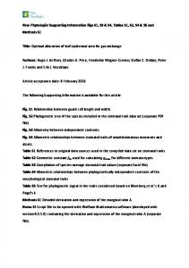
In the Part 9 of the standard, an ASIL decomposition approach is introduced allowing to reduce the safety levels by decomposing the safety requirements over redundant and sufficiently independent elements. The decomposition when applied results in safety requirement with lower ASIL allocated to the redundant elements. Since higher ASIL implies higher cost, the ASIL decomposition can help to meet the safety requirements without incurring excessive costs. Its application must though verifies different requirements that are detailed in [4]. The reader can refer to [4] and [5] for examples of application of ASIL decomposition. The decomposition follows predefined patterns. In Fig 1, we can see the different applicable patterns. For example, an ASIL D could be decomposed in three different ways.
Fig. 1. ASIL D decomposition Patterns
The resulting decomposed requirements could also be decomposed subsequently, since, multilevel decomposition is allowed by the standard. In the design cycle, the designers could resort to ASIL decomposition at different levels : system, subsystems, software and hardware. This results in multiple possible allocations. Finding an effective allocation that answers to the different safety goals without incurring unnecessary development constraints is crucial. Often manually performed,
the complexity of the systems and the multiple failures modes of its sub-systems make it error prone. An automatic approach to allocate the ASIL is indeed needed to ensure the consistency and the optimality of the solution. In this paper, we propose an approach for an automatic decomposition and allocation of ASILs. It allows finding all the possible allocations not only with respect to the different safety goals but also with respect to the analyst preferences. The approach is based on the minimal cut sets extracted from the fault tree for the considered safety goals. A matrix approach is used to formulate and retrieve the solution set. The rest of this paper is organized as follows: In the first section, we review the previous works on the automatic allocation of safety levels. In section 2, we present our approach with a small example to explain the different steps. In section 3, we present the experimental evaluation results on a generic example. II. A DVANCES ON AUTOMATIC SAFETY LEVELS ALLOCATION
The SIL concept was adopted by the standards derived from IEC 61508. The allocation and decomposition process differs though among these standards. For a comparison of the different concepts, the reader may refer to [16]. These differences in the allocation approach makes the works on determination of SILs such as [6],[7] and [8] unapplicable in the ISO 26262 context. The cited works are based on probabilistic approaches to determine the SIL. While, in the ISO 26262, the ASIL determines the quantitative targets concerning the random hardware failures and not the other way around. In [9], a tool for Development Assurance Level (DAL) allocation, i.e, DALCULATOR is proposed. The allocation and decomposition problem is solved using a Pseudo-Boolean logic. The allocation approach in the ARP-4754, a guideline for development of civil aircraft and systems, seems to present more similarities than the previous works in the fact that it is a qualitative approach. But, such tool can not be used in an automotive context. Unlike the ASIL decomposition, the tool doesn’t aim to a requirement decomposition over the redundant elements. It aims at downgrading the DAL to the really needed level in case of independent elements. In the ISO 26262 context, [10] proposed an approach to allocate the ASILs to the system components. The allocation process and decomposition algorithm were implemented in HIP-HOPS, a safety analysis and optimization tool [15]. The proposed algorithm exhaustively explores the different possible ASIL allocations and leaves to the analyst the choice of the allocation to be implemented afterwards. This algorithm was enhanced for better performance and presented in [14]. Although the algorithm has the advantage of finding all the possible allocations, it has a main drawback. The processing time could reach dozens of hours for large scale systems. The approach in [11], on the other hand, avoided the exhaustive search by aiming to find an optimal allocation. In this approach, numerical values are associated to ASILs and are used as a cost indicator. It could be considered as
a simple cost model. As for the allocation problem, it is interpreted as a linear program. The set of MCS are interpreted as the constraints. Whereas, the objective function is the cost of the system, considered in this case as the sum of the ASILs allocated to the different components of the system. The main advantages of this approach are the simplicity of implementation and the processing time. The approach takes also into account the preferred ASIL for specific components, which makes it more adapted to industrial cases where the reused components are preferred to be allocated the same ASIL. But, the simple cost model adopted here is the main disadvantage. It suggests in this case that subsystems or components with the same ASIL have the same cost or impact on the solution rating. The result of the optimization could be misleading since subsystems, at the same ASIL, with different complexities or sizes have not necessarily the same cost. A more elaborated cost model is, in this case, necessary for better optimization results. For large scale systems, [12] and [13] preferred the optimization heuristics as an approach to reach an optimal allocation. The heuristics are known to have better performance in larger problems. The solution is found faster but there is no guarantee that the found solution is a global optimal one. [12] used a penalty based algorithm whereas [13] used a Tabu search algorithm. They tested the approach using different generic simple cost models (linear, logarithmic ...). The results of the runs showed that the obtained solution depends tightly on the used cost model. Though no efficient cost model that would take into account the different parameters were proposed. In the industry, different cost models are used. But, as far we know, no cost model that efficiently take into account the impact of the ASIL on the development cost has been proposed. We think that in this case it would be complicated to use the linear program and heuristics solving approaches. On one hand, their results depend tightly on the used cost model and on the other hand, they limit the analyst/designer to a unique solution. Thus, we propose, here, an alternative approach to find the possible allocations by interpreting the problem as system of linear equations. On the other hand, the previously presented approaches aims to allocating ASIL to components or to their failure modes. In our approach, we decided to allocate them to functions. III. ASIL ALLOCATION AS A SYSTEM OF LINEAR EQUATIONS
The decomposition patterns specified by the standard can be formalized. By assigning numerical values to the ASIL (QM = 0, A = 1, B = 2, C = 3, D = 4), the patterns are verified by the following equation: X
ASILi = ASILSR
(1)
The decomposition is in respect with the patterns if the sum of the values of the allocated ASILs are equal to the original ASIL value of the decomposed safety requirement.
The obtained requirement from decomposition are implemented by sufficiently independent redundant elements. These elements ensure, each separately, the non violation of the safety requirement. Thus, the safety requirement can be decomposed over elements if their loss, only jointly, lead to the violation of the safety requirement. In a functional architecture of the system, these elements are functions. When an architecture for the system is conceived, safety analysis techniques such as FTA can then lead us to the functions over which an ASIL decomposition could be applied. MCS helps identifying these functions whose loss jointly leads to the violation of the safety requirements. The safety requirement implemented by these functions can then be allocated ASIL values that verifies equation (1). Let’s assume from this point onward that the ASIL allocated to a function in the architecture refers to ASIL allocated to the safety requirement implemented by this function. In this case, for every MCS leading to violation of a safety requirement, the functions Fi in the architecture verifies the following equation where the coefficient ai is null if the corresponding function loss is not in the MCS and equal to 1 otherwise X ai × ASILF i = ASILSR (2) Applied to all the MCS for all the safety requirements (SRi), the allocation problem could be interpreted as a system of linear equations. In a matrix form, a possible allocation should be solution to the equation (3)
a1n ASILF 1 ASILSR1 .. × .. .. = . . . amn ASILF n ASILSRn (3) During this phase, the analyst could prefer a function to be at a specified ASIL. In other cases, he could specify if two functions are not sufficiently independent. It is possible to retrieve the solutions that match these preferences. An extra constraint could be added to the system in the form of an equation. To avoid increasing the size of the system and the resolution time, we take these constraints into account by adapting the original system. To fix a variable at the preferred ASIL, we withdraw its corresponding column from the system after extracting it from the left part of the equation (3). In order to take into account the non dependency of two variables, we merge their corresponding columns using logic ’OR’ operation. Once obtained, the augmented matrix form of the system taking into account all the constraints, we proceed to solving it. Different solving approaches could be used to solve the linear systems. The allocation problem, though, admits often multiple solutions. Thus, many of these approaches could not be applied since the obtained system’s matrix is not always square. The simplest approach, in this case, would be to iterate through all the possible values of the variables. Instead we propose to use a classical approach using the Row Reduced Echelon Form (RREF) of the system. a11 .. . am1
··· .. . ···
The RREF is generally computed using Gauss-Jordan elimination. It allows to identify the basic and the free variables which corresponds to the columns with no leading entry. In order to find the solutions, we proceed into allocating to these variables a value in the the range of ASILs numerical values, {0,..,4}, and deduce the rest of the variables accordingly. The echelon form could also be used to test the solvability of the system. If equations of the form 0 = Cst, where Cst is non null, exist, we may deduce that no possible allocation can be found. In this case, the analyst could proceed into ignoring the preferred ASIL or review the system. The major steps of the solving approach are described in Algorithm 1: The RREF and solve functions allows respectively, to calculate the row reduced echelon form and to solve the system. The Fix-value function, on the other hand, allows to fix the value of the variables in the systems. It consists of extracting a new system from the original one by eliminating the fixed variables. The merge-dependent function allows to merge the columns corresponding to dependent variables. Algorithm 1 ASIL Allocation Solving approach Input: Mat(m,n+1): the system augmented matrix form m : number of MCS n : number of FM dependent-var : list of dependent variables preferred-asil : list of functions and their preferred ASIL Output: Set of possible allocations Algorithm: initialization; Mat ← Merge-dependent (Mat,dependent-var) Mat ← Fix-value(Mat,preferred-asil) Mat ← RREF(Mat) List-free-var ← find-free-var (Mat) Iterate through the possible values of the free variables { Fix-value(Mat, List-free-var) if solve(Mat) in {0,..,4} then Solution = Solution ∪ solve(Mat) end if } IV. E XPERIMENTAL EVALUATION A. Example Next is an illustrative example for the decomposition. We consider a system with two safety requirements (SR1 and SR2) rated ASIL D and ASIL C respectively. The functional elements F1 ... F5 implement these safety requirements. The Fault Tree in Fig.2 describes how the loss of these functions could lead to the violation of the safety requirements. SR1 and SR2 can be decomposed over the element whose failure lead to the violation of the requirement. For example, SR1 can be decomposed over F2, F3 and F4. In order to find the different possible ASIL combinations that could be allocated to these elements, we use the approach presented in the previous section.
we extract from the last column the third column C3 multiplied by the numerical value associated to ASIL C C6 ← C6 − (3 × C3 ). C3 is then removed and the system matrix becomes as follows : 1 0 0 0 4 0 1 1 0 1 0 0 1 1 0 The next step is to reduce the matrix to its row echelon form. It shows that the variables ’x4’ and ’x5’, corresponding to the fourth and fifth column in the matrix, are the only free variables (in the case with no preferred ASIL). 1 0 0 0 0 4 0 1 0 0 −1 1 0 0 1 1 1 3 In this case, we will have 25 iterations as these variables take the values from 0 to 4. We will limit here to the two first iteration where (x4 = 0, x5 = 0) and (x4 = 0, x5 = 1) . 1st iteration : The system to solve becomes 1 0 0 4 0 1 0 1 0 0 1 3
Fig. 2. FT example
We apply the algorithm described above to explain step by step how it works. From this FT, three MCS lead to the violation of the SRs. • (Loss of F1) : ASIL D • (Loss of F2, Loss of F3, Loss of F4) : ASIL D • (Loss of F3, Loss of F4, Loss of F5) : ASIL C We suppose that the functions F1 to F5 are sufficiently independent, as required to apply the decomposition. The ASILs allocated to these functions should verify then : ASIL(F 1) = 4
(4)
ASIL(F 2) + ASIL(F 3) + ASIL(F 4) = 4
(5)
ASIL(F 3) + ASIL(F 4) + ASIL(F 5) = 3
(6)
The possible allocations are thus solutions to the following equation :
1 0 0
0 1 0
0 1 1
0 1 1
ASIL(F 1) 0 4 .. 0 × 4 = . 1 3 ASIL(F 5)
(7)
At this level, it is possible to take into account the preferred ASILs for a specific event. For example, if we would like the ’F3’ to be allocated an ASIL C. The system could be modified to take this information into account by withdrawing the corresponding variable from the system : Using the augmented matrix: 1 0 0 0 0 4 0 1 1 1 0 4 0 0 1 1 1 3
A first allocation could be than deduced where: ASIL(F1)=4; ASIL(F2)=1; ASIL(F3)=3; ASIL(F4)=0; ASIL(F5)=0; 2nd iteration : The system to solve becomes 1 0 0 4 0 1 0 2 0 0 1 2 A second allocation could be than deduced where: ASIL(F1)=4; ASIL(F2)=2; ASIL(F3)=2; ASIL(F4)=0; ASIL(F5)=1; Continuing the next iterations will allow us to find the rest of the possible solutions. B. Results Applied on the example, it was possible to retrieve all the possible allocations, 10 in total. The processing time was very small, less than a second. We applied it also on different generic examples along with the algorithm proposed in [14] (Algorithm 2) to compare the results and the processing time. The examples are inspired from VALEO project examples in their size and the FT structure. The tests were carried out on a machine equipped with an Intel I5 processor and 4 GB of RAM. 5 10 24 48
Example Size Functions, 3 MCS Functions, 19 MCS Functions, 30 MCS Functions, 44 MCS
Nbr possible allocations 10 1 3 75 TABLE I T ESTS P ROCESSING T IME
Alg 1 0,01 0,09 0,04 0,76
Alg 2 0,1 356,16 0,34 1,4
Both algorithms succeeded in finding all the possible allocations. The processing time logically increased with the size of the problem. But, the algorithms were impacted differently. The algorithm 2 is more sensitive to the length of MCS because of its resolution approach which is based on iterations over the possible allocations for each MCS. With an example where the mean length of the MCS is a little higher, a gap appears between the performances of the two algorithm. Our approach seems, on the other hand, less impacted by this issue. Our approach takes also into account the independence parameter into account, an important factor that can influence the allocations which is not taken into account in the algorithm 2. It has also the advantage of taking into account the preferred ASIL and the possibility of avoiding unnecessary resolution effort if no solution exists. V. C ONCLUSIONS AND F UTURE W ORK In the automotive industry, the safety requirements have a considerable impact on the safety critical systems architecture and cost. The allocation and decomposition of ASILs in the ISO-26262 context is crucial to reach an optimal design whether in complexity or in development cost. Yet the size and complexity of the architectures make the allocation process difficult and error prone if done manually. Several works proposed approaches to automate the process. These approaches provide often a unique optimal solution whereas multiple alternatives are often possible. The objective of these approaches being to assist the analyst or designer, reducing the choice to a unique solution is limiting. Thus, we proposed in this article an approach to interpret and solve the ASIL decomposition problem, capable of providing multiple solutions with acceptable processing time for small and medium size cases. Interpreting the decomposition problem as a system of linear equations allowed not only to find all the possible allocations but also to take into account the preferences of the analyst and the dependency between the functions. Whereas in this paper we focused on exploring the different possible allocations, we think that in order to reach an optimal design, it is necessary to investigate the allocation problem with more constraints. Our future works will focus on the automatic allocation at a functional level where more parameters should be taken into account, such as the hardware allocation of the functions. Often physical architecture may impose more constraints on the safety level some functions can guarantee. It could also fail to guarantee the independence requirements which lead to developing some functions at higher level than previewed. R EFERENCES [1] ISO 26262: Road Vehicles - Functional safety, International Organization for Standardization (2011) [2] : International Electrotechnical Commission. Functional Safety of Electrical /Electronic /Programmable Electronic Safety-Related Systems. Parts 1 to 7, 1998 [3] Liaigre, D. (2008). Impact de lISO 26262 sur l e´ tat de l ´art des concepts de s e´ curit automobile actuels, 19. [4] Ward, D. D., Crozier, S. E. (2012). The uses and abuses of ASIL decomposition in ISO 26262. 7th IET International Conference on System Safety, incorporating the Cyber Security Conference 2012, 5151. doi:10.1049/cp.2012.1523
[5] Izosimov, V., Ingelsson, U., Wallin, A. (2012). Requirement decomposition and testability in development of safety-critical automotive components. Computer Safety, Reliability, and , 7486. [6] Sallak, M., Simon, C., Aubry, J. (2008). A fuzzy probabilistic approach for determining safety integrity level. Fuzzy Systems, IEEE , 110. [7] Beugin, J., Renaux, D., Cauffriez, L. (2007). A SIL quantification approach based on an operating situation model for safety evaluation in complex guided transportation systems. Reliability Engineering and System Safety, 92(12), 16861700. [8] Lee, Y., Kim, J., Kim, J., Moon, I. (2009). A Verification of Fault Tree for Safety Integrity Level Evaluation, 55485551. [9] Bieber, P., Delmas, R., Seguin, C., Belin, E. (2011). DALculus Theory and Tool for Development Assurance Level Allocation, 4356. [10] Papadopoulos, Y., Walker, M. (2010). Automatic allocation of safety integrity levels. : robustness and safety, 47. [11] Mader, R., Armengaud, E. (2012). Automatic and optimal allocation of safety integrity levels. Reliability and , 16. [12] Parker, D., Walker, M., Azevedo, L., Papadopoulos, Y., Arajo, R. (2013). Automatic Decomposition and Allocation of Safety Integrity Levels Using a Penalty-Based Genetic Algorithm. In M. Ali, T. Bosse, K. Hindriks, M. Hoogendoorn, C. Jonker, J. Treur (Eds.), Recent Trends in Applied Artificial Intelligence SE - 46 (Vol. 7906, pp. 449459). Springer Berlin Heidelberg. [13] Azevedo, L., Parker, D. (2013). Automatic Decomposition of Safety Integrity Levels: Optimization by Tabu Search. Safety) of the 32nd . [14] Maenad. (2012). Model-based Analysis and Engineering of Novel Architectures Dependable Electric Vehicles. [15] Papadopoulos, Y., Walker, M., Parker, D., Rde, E., Hamann, R., Uhlig, A., Lien, R. (2011). Engineering failure analysis and design optimisation with HiP-HOPS. Engineering Failure Analysis [16] Blanquart, J., Astruc, J. (2012). Criticality categories across safety standards in different domains. ERTS-2012.