**Interdisciplinary Program of Integrated Biotechnology, Sogang University. C.P.O. Box ... rect them using software such as Adobe® PhotoShop. Conventional.
16th European Signal Processing Conference (EUSIPCO 2008), Lausanne, Switzerland, August 25-29, 2008, copyright by EURASIP
AUTOMATIC DETECTION AND CORRECTION OF PURPLE FRINGING USING THE GRADIENT INFORMATION AND DESATURATION Baek-Kyu Kim* and Rae-Hong Park*, ** *
Department of Electronic Engineering, Sogang University Interdisciplinary Program of Integrated Biotechnology, Sogang University C.P.O. Box 1142, Seoul 100-611, Korea phone: + (822) 705-8463, fax: + (822) 706-4216, email: {ohn109, rhpark}@sogang.ac.kr web: http://eevision1.sogang.ac.kr **
ABSTRACT This paper proposes a method to automatically detect and correct purple fringing that is one of the color artifacts due to characteristics of charge coupled device sensors in a digital camera. The proposed method consists of two steps. In the first step, we detect purple fringed regions that satisfy specific properties: hue characteristics around highlight regions with large gradient magnitudes. In the second step, color correction of the purple fringed regions is made by desaturating the pixels in the detected regions. The proposed method is able to detect purple fringe artifacts more precisely than Kang’s method. It can be used as a post processing in a digital camera.
1.
INTRODUCTION
Recently digital cameras are widely used, with the technologies rapidly advancing. Functions of a digital camera are applied to other digital consumer products. It is on the verge of a digital convergence era. The digital camera function of a cellular phone is a good example of digital convergence. A big difference between the digital and analog cameras lies in a sensor employed. A sensor of an analog camera is a film whereas that of a digital camera is an image sensor. An image sensor converts incident light to an electrical signal [1]. Color artifacts not shown in an image obtained from an analog camera appear in an image from a digital camera. In a digital camera, the causes of color artifacts are due to characteristics of an image sensor or an optical device [2] [3] [4] [5]. Purple fringing is one of the color artifacts. Because purple fringing is unpleasant to the eye, users are likely to eliminate or correct the purple fringed pixels. For example, purple fringing appears at the edge where colors (hue and intensity) suddenly change because of blooming, demosaicing, and chromatic aberration. Blooming and demosaicing are characteristics of an image sensor (i.e., CCD sensor), whereas chromatic aberration is a characteristic of an optical device (i.e., lens). In the case of chromatic aberration, which is a problem caused by optical characteristics, users can see purple fringing in an image obtained by both the digital and analog (film) cameras. Image quality of digital cameras depends on the type of artifacts. Fortunately, artifacts of digital images are corrected easily by post processing in digital image device or graphic editor software. Because digital image file format contains color or intensity information at each pixel, digital images are rectified more easily than analog ones that are obtained by developing a film and printing a photograph. At present, most users select the regions which contain the purple fringed pixels, and correct them using software such as Adobe® PhotoShop. Conventional and proposed methods automatically detect and correct the purple fringed pixels. Also, they can be used as a post processing in a digital camera, enhancing the image quality.
An existing method (Kang’s method) [6] detects and corrects the color artifacts that have the purple color tone, which are called purple fringing. Unfortunately, Kang’s method has a weakness that it may detect and correct even intact pixels because it uses only two properties: purple fringed pixels appear near bright regions with color characteristic. In this paper, we aim to detect purple fringe artifacts more accurately than Kang’s method [6] by expanding the color range for accurate detection of purple fringing using the gradient magnitude information of an image. The rest of the paper is organized as follows. In Section 2, we explain causes of purple fringing. Existing and proposed methods for detection and correction of purple fringing are explained in Sections 3 and 4, respectively. Then, experimental results and discussions are presented in Section 5, and finally conclusions are given in Section 6.
2.
PURPLE FRINGING
Purple fringing is caused by three factors. Firstly, blooming is produced by inherent characteristics of a charge coupled device (CCD) sensor in a digital camera. CCD sensor converts incident light to an electrical signal. For example, in a digital camera an image of an object is sensed as a form of light through a lens. Photodiodes which are light sensors in a CCD sensor generate charges by light, in which a single cell of a CCD sensor defines a pixel and each pixel has a quantum-well where charges are accumulated [1]. The highlight in an image makes the pixel intensity distorted. In other words, the high luminance makes charges flooded over the quantum-well. When charges exceed the storage capacity of the quantum-well, the excessive charges move to the adjacent cells through a readout line. The moving charges produce an error in the measurement of luminance, which is called blooming [2]. Secondly, the false color effect is caused by demosaicing. CCD’s configuration is usually known as the Bayer pattern, in which any 2× 2 photosite group of the color filter array (CFA) consists of two green, one blue, and one red photosites. When the signal of an image is inputted through a single CCD sensor, each photosite receives selectively a single signal of the R, G, and B color, where symbols R, G, or B denote red, green, and blue, respectively. Because three channels (R, G, and B) have empty pixels that do not have specific color values, missing colors are to be interpolated for generation of a full-color image. However, interpolation gives artifacts due to inconsistency among three color planes. The artifacts appear due to abrupt hue change around color discontinuities, called false colors [3] [4]. Finally, chromatic aberration is due to an optical characteristic of a lens. Each specific region of visible light has different wavelength. The longer the wavelength, the higher a refractive index. In the case of a digital camera, three (R, G, and B) lights are used. The R, G,
16th European Signal Processing Conference (EUSIPCO 2008), Lausanne, Switzerland, August 25-29, 2008, copyright by EURASIP
and B lights have wavelength of about 650nm, 510nm, and 475nm, respectively. They have wavelength-dependent refractive indices, thus the chromatic aberration occurs in transverse or longitudinal direction. As a result, each of R, G, and B channels shows a blurred focus at different locations. Especially, purple fringing arises near edges which have large luminance differences [5].
3. 3.1
KANG’S METHOD
Detection of Purple Fringing
According to Kang’s method [6], the purple fringed regions are detected by expanded near-saturated regions (NSRs) and candidate regions (CRs). In other words, Kang’s method simply compares boundary of expanded NSRs with CRs. 3.1.1 NSRs A major cause of purple fringing is a blooming effect caused by an object having the high luminance [6]. The maximum intensity value is assumed to be 255 (i.e., quantized to eight bits), then we find the pixels that are assumed to be influenced by high luminance. In Kang’s method, pixels are chosen as near-saturated pixels if the intensity value of the pixels is greater than or equal to 230 (i.e., the near-saturation threshold). 3.1.2 CRs CRs are detected by color analysis of an image. Purple fringe artifacts occur at pixels where purple color is emphasized. Purple is nonspectral color in chromaticity diagram of the Commission International de L`Eclairage (CIE) color model. The color can be represented by mixing red and blue. However, NSRs has color information as white light that is perceived when all three cones are stimulated. The color of the purple fringing near white light is seen when light from many different wavelengths is mixed. Therefore, color information (R, G, and B) is considered in detecting CRs. In general, the B color intensity value is greater than the R and G color intensity values. When the RGB color cube is represented in the RGB space, we can assume that the partial volume of purple fringing satisfies the condition, in which the difference between B and G color intensities is greater than 25 and that between B and R color intensities is greater than 25. If any pixels are included in the range, they are selected as CRs [6].
3.2
Correction of Purple Fringing
In Kang’s method, three techniques were presented to correct purple fringing. The first technique is to consider color of neighboring pixels of purple fringed pixels. It converts color of the purple fringed pixels into near monochrome. In other words, there is a gradual change from color to near monochrome. The method achieves a linear modification between pure color and pure monochrome. Intact pixels have the pure color, while purple fringed pixels have the pure monochrome. The second technique is simply to assign the mean value of RGB color to the purple fringed pixels. The modified RGB values have the same value, thus the purple fringed pixels turn into black and white. The third technique is to set the R and B color intensity values to the G intensity value. Most image sensors (CCD) in digital cameras are arranged according to the Bayer CFA pattern. Components of the Bayer CFA pattern consist of two G, one B, and one R photosites. Because G photosites take up most of space in image sensor, the G color intensity values have the implicit higher reliability. Therefore, the G color intensity values are used as the reference color. Any of three techniques can be used for correction of purple fringing [6].
4.
PROPOSED METHOD
4.1 Detection of Purple Fringing The proposed method similarly detects purple fringed regions by extracting NSRs and CRs, which is similar to Kang’s method [6]. To segment the NSRs and CRs, the proposed method converts an original image into a binary image, which is suitable for a binary morphology operation. The proposed method modifies the condition of CRs in order to detect the purple fringed pixels in a broader purple color range. In addition, it uses the gradient magnitude information of an image. In other words, purple fringed regions are determined based on the comparison of NSRs and CRs as well as the gradient magnitude of an image. Figure 1 shows the block diagram of the proposed method for detection and correction of purple fringing, which consists of two parts: detection and correction parts. 4.1.1 Binarizatoin of NSRs The NSRs are binarized, to which a binary morphology is applied. By the way, blooming is a big problem for the sensing of the image with highlight regions. Unfortunately, it is interrelated with other effects, which is common in digital cameras. Spatial averaging reduces the fluctuation of the sensing characteristics in the array, due to which blooming is “smoothed” over the image. As a result, if we set a threshold value to the maximal intensity (i.e., 255), we cannot detect the highlight regions because of the spatial averaging, which is spread over adjacent pixels. Thus, we assume that the upper 10% of the intensity value is potentially influenced by blooming [7]. For example, we set a threshold value to 90% of the maximum intensity value, i.e., 230. If a pixel intensity of an image is larger than the threshold value T, the pixel value is set to ‘1’, otherwise, set to ‘0’. Through this binarization, we can obtain the binary image which indicates highlight regions. The binary image NSR is defined as I ( x , y ) + I G ( x, y ) + I B ( x , y ) ⎧ ⎪1, if R >T NSR ( x, y ) = ⎨ 3 ⎪⎩0, otherwise
(1)
where I R ( x, y ), I G ( x, y ), and I B ( x, y ) represent R, G, and B components of the original image, respectively, and T denotes the threshold, i.e., 230. 4.1.2 Modified CR Condition The proposed method uses the modified CR condition so as to detect the purple fringed pixels in a broader purple color range. In Kang’s method, color information of purple is restricted only when B component is larger than R component and B component is larger than G component. However, the purple fringed pixels often occur in NSRs when R component is larger than B component, too. Because NSRs have white color component, the color artifacts are especially conspicuous in NSRs. Therefore, in the proposed method
Figure 1. Block diagram of the proposed method.
16th European Signal Processing Conference (EUSIPCO 2008), Lausanne, Switzerland, August 25-29, 2008, copyright by EURASIP
the CRs condition is modified to include that case as artifacts. The modified CR condition (CR ' ) is represented as
if I R ( x, y ) − I B ( x, y ) < Td ⎧ ⎪1, CR' ( x, y ) = ⎨ and I B ( x, y ) − I G ( x, y ) > Td ⎪0, otherwise ⎩
(2)
where Td represents the difference threshold, which is experimentally set to 25 [6]. 4.1.3 Gradient Information In addition, the proposed algorithm uses the gradient magnitude of an image. Kang’s method [6] has a drawback that it detects even the intact pixels. For example, if intact pixels having purple color are included in the CRs, the pixels are regarded as a part of purple fringed regions. The proposed algorithm considers the hue value and the spatial adjacency between the NSRs and CRs. However, purple fringing occurs restrictively in narrow regions of boundary, i.e., purple fringing appears near edges where color intensity or hue changes abruptly. Thus, we first find edge pixels among candidate regions, so the proposed method additionally uses the gradient magnitude of an image. To make use of the color changes for detection of purple fringing, we convert (requantize) each channel of an image into a 4-level image, in which the color value between the maximum and minimum values is nonuniformly quantized to four levels. By requantizing the color value into only four levels, the advantage is to map the gradient values to simple numerals. Thus, to detect the boundaries where purple fringing occurs, we do not have to use a timeconsuming operation. In other words, the proposed method only checks whether each pixel has a zero or nonzero gradient value. The purple fringing is seen frequently near the bright regions. Especially the artifacts of bright purple tone are harsh to an eye. Therefore, we nonuniformly divide the color range to accurately detect the bright purple fringing. The image of each channel is represented as (nonuniformly quantized to four levels)
(a)
⎧ ⎪3, ⎪ ⎪2, ⎪ QIC (x, y) = ⎨ ⎪1, ⎪ ⎪ ⎪⎩0,
7 (ICmax − ICmin) < IC (x, y) ≤ ICmax 8 7 3 (ICmax − ICmin) < IC (x, y) ≤ (ICmax − ICmin) 8 4 3 1 (ICmax − ICmin) < IC (x, y) ≤ (ICmax − ICmin) 4 2 1 ICmin ≤ IC (x, y) ≤ (ICmax − ICmin) 2
(3)
where I C (C = R, G, or B) represents the color intensity of channel C, ICmax and ICmin denote the maximum and minimum color values of I C , respectively. Subsequently, we compute the gradient magnitude value of each channel image as 2
2
⎛ ∂QI C ( x, y) ⎞ ⎛ ∂QIC ( x, y) ⎞ ⎟⎟ . | ∇QI C ( x, y) |= ⎜⎜ ⎟⎟ + ⎜⎜ ∂x ∂y ⎝ ⎠ ⎝ ⎠
(4)
Gradient values are not zero in abrupt luminance change regions around edges. In R, G, and B channels, some pixels with a nonzero gradient value may be located at different positions, inducing color fringing. Pixels having the nonzero gradient values are set to ‘1’, otherwise, set to ‘0’. A binary gradient magnitude (BGM) image is defined as if | ∇QI R ( x, y) |≠ 0 or | ∇QIG ( x, y) |≠ 0 ⎧ ⎪1, BGM ( x, y) = ⎨ or | ∇QI B ( x, y) |≠ 0 ⎪0, otherwise. ⎩
(5)
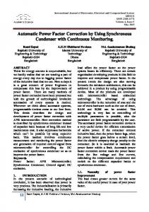
To show the effect of the different number of quantization levels and the type of quantization (uniform/nonuniform), we perform an experiment by applying different types of quantization to the original image, as shown in Figure 2(a). In the next subsection, we show the detection result by three different quantization schemes (i.e., uniform two-level, uniform four-level, and nonuniform four-level).
(b)
(c)
(d)
(e)
(f)
(g)
Figure 2. Performance comparison (detection and correction of purple fringing, three quantization schemes), (a) Test image, (b) Detection result by the uniform quantization (two levels), (c) Detection result by the uniform quantization (four levels) (d) Detection result by the nonuniform quantization (four levels, proposed method), (e) Correction result by the uniform quantization (two levels), (f) Correction result by the uniform quantization (four levels), (g) Correction result by the nonuniform quantization (four levels, proposed method).
16th European Signal Processing Conference (EUSIPCO 2008), Lausanne, Switzerland, August 25-29, 2008, copyright by EURASIP
4.1.4 Detection Result Purple fringed pixels, which belong to CRs, appear near NSRs. As a boundary of the NSRs is expanded, some boundaries of the expanded NSRs overlap with CRs. According to Kang’s method [6], the intersection regions where CRs are overlapped with expanded NSRs are considered as purple fringed regions, in which if CRs include intact pixels, the pixels are also regarded as pixels to be corrected. On the contrary, the proposed method, using the gradient magnitude information, detects purple fringed pixels more restrictively. Purple fringed pixels are detected if the BGM value at a pixel is equal to ‘1’ and the pixel also belongs to intersection regions of expanded NSRs and CRs. Figures 2(b), (c), and (d) show the detection results of purple fringed pixels of Figure 2(a) by the uniform quantization (two levels), uniform quanrization (four levels), and nonuniform quantization (four levels), respectively. When each channel of an image is uniformly quantized to two levels, the detected purple fringed pixels are shown in the narrow region of the water pipe and some window frame (Figure 2(b)). To detect the purple fringing in broader regions, we uniformly quantize each channel to four levels. Consequently, quite a number of purple fringed pixels are detected in the water pipe (Figure 2(c)). Note that, the proposed method nonuniformly quantizes each channel of an image to four levels in order to detect the purple fringed pixels near bright side (Figure 2(d)).
4.2
Correction of Purple Fringing
Purple fringed pixels have purple or near blue color. Because the color of artifacts tinged with purple is unpleasant to an eye, purple fringed pixels are converted to monochrome [6]. To put it another way, the correction method is to reduce purple color of artifacts. In the hue/saturation/intensity (HSI) space, the vertical axis represents the intensity [8]. Hue is represented by the angle of the vector to the point with respect to the R axis in the chromaticity plane (H and S). Saturation is expressed by the distance which is the length of the vector from the origin to the point. To reduce the purple color, the compulsory saturation value is set to ‘0’, which is called desaturation. In other words, desaturation replaces a color of purple fringed pixels by an achromatic color. The desaturation step is described in the following. To desaturate the purple fringed pixels, we must assign the value of saturation S to zero. For example, when the angle of H is in the range from 0° to 120°, color value of B is the same as an intensity value. Then, because the value of saturation is zero, color value of R is also equal to the intensity value. Due to the normalization of color values of R and B, color value of G is also the same as the intensity value. In other words, R, G, and B colors have the same average value of RGB. The desaturating equation can be written as
I C' ( x, y) =
I R ( x, y ) + I G ( x, y ) + I B ( x, y ) 3
(6)
where I C' (C = R, G, or B) represents the new color intensity of channel C. Note that equation (6) is equivalent to the second correction scheme of Kang’s method [6]. Finally, the purple color of artifacts is reduced by desaturation. As a result, the correction method turns color of purple fringing to monochrome color. Figures 2(e), (f), and (g) show the correction results by desaturation. In the case of the two-level quantization, the correction image still has a little bit of purple color tone (Figure 2(e)). Also, the purple fringed pixels still remain near the bright region of the water pipe in the corrected image (Figure 2(f)). Thus, in order to detect and correct the purple fringed pixels in the bright region side, we nonuniformly quantize each channel to four gray levels. As a result, the remaining purple fringed pixels are successfully corrected near the bright region of the water pipe (Figure 2(g)).
5.
EXPERIMENTAL RESULTS AND DISCUSSIONS
We experiment with a number of real images containing purple fringed pixels. Figure 3(a) shows an example of a signboard test image which has purple fringed pixels at the white boundary. Figures 3(b) and (c) show NSRs and pixels having a nonzero gradient magnitude, respectively. Figures 3(d), (e), and (f) show CRs, detection result, and correction result of Kang’s method, respectively. Figures 3(g), (h), and (i) show those of the proposed method, respectively. Due to abrupt hue or intensity changes, we can see the purple fringed pixels at the boundary of white circle and character ‘i’. To detect the purple fringing, first of all we extract NSRs (Figure 3(b)) and CRs (Figures 3(d) and (g)). Because detection color range of the proposed method is broader than that of Kang’s method, CRs image of Kang’s method (Figure 3(d)) is different from that of the proposed method (Figure 3(g)). Then, we obtain the binary images NSR and CR. The binary images are used for finding the adjacency between NSRs and CRs. If the expanded NSRs overlap with some CRs, the CRs correspond to the purple fringed pixels. In Kang’s method, purple fringed pixels are decided through the adjacency between NSRs and CRs alone (Figure 3(e)). Then, the purple fringed pixels are corrected by averaging color values (R, G, and B) of the detected pixels. Figure 3(f) shows the correction result by Kang’s method. On the contrary, in the proposed method, we find the pixels having nonzero gradient magnitudes (Figure 3(c)). If some pixels have nonzero gradient magnitudes in the regions where NSRs overlap with CRs, they are determined as purple fringed pixels. Figure 3(h)
(a)
(b)
(c)
(d)
(e)
(f)
(g) (h) (i) Figure 3. Comparison of simulation results (detection and correction of purple fringing in the signboard image), (a) Test image, (b) NSRs, (c) Pixels having nonzero gradient magnitudes, (d) CRs (Kang’s method), (e) Detection results (Kang’s method), (f) Correction results (Kang’s method), (g) CRs (proposed method), (h) Detection results (proposed method), (i) Correction results (proposed method).
16th European Signal Processing Conference (EUSIPCO 2008), Lausanne, Switzerland, August 25-29, 2008, copyright by EURASIP
shows the detection result of proposed method. By desaturating color of the detected pixels using equation (6), we obtain the final result (Figure 3(i)). Figures 3(f) and (i) show the performance comparison between Kang’s method (Figure 3(f)) and the proposed method (Figure 3(i)). The proposed method shows better results than Kang’s method because the former detects the purple fringed pixels in a broad range. However, purple fringing is incorrectly detected when an image contain intact pixels with purple color tone. For example, Figure 4(a) shows a girl who wears a sweater in purple color tone. Figure 4(b) and (c) show NSRs and pixels having nonzero gradient magnitudes, respectively. Figures 4(d), (e), and (f) show CRs, detection result, and correction result of Kang’s method, respectively. Figures 4(g), (h), and (i) show those of the proposed method, respectively. From Figure 4(a), the waterdrops with relatively bright tone is overexposed because the exposure of an image is fixed at the sweater with dark purple tone. As a result, the purple fringed pixels are also detected in the girl’s sweater because the differences of hue and intensity are large between the sweater and waterdrops. Figure 4(b) shows NSRs of Figure 4(a). Due to stream of water, overexposed regions where NSRs have highlight color tones are scattered throughout. We can see that the artifact pixels are extracted along with intact pixels in the result of CRs (Figures 4(d) and (g)). In Kang’s method, detection image (Figure 4(e)) is similar to CRs (Figure 4(d)) because most CRs are connected with NSRs. Then, the corrected resultant image (Figure 4(f)) is obtained by averaging the color values (R, G, and B) of the detected purple fringed pixels.
In the proposed method, we consider the abrupt change of color near bright region (i.e., waterdrop in fountain). Figure 4(c) shows a large number of pixels having the nonzero gradient magnitude in a fountain and waterdrops because a nonuniformly quantized 4-level image represents the small change in the gradient magnitude near bright regions. On the other hand, the gradient values are zero in the girl’s sweater because the sweater has slight level change in a quantized 4-level image with regard to dark purple tone. Then, we can detect correctly purple fringed pixels using the NSRs (Figure 4(b)), CRs (Figure 4(g)), and the gradient magnitude (Figure 4(c)). Figure 4(h) shows the resultant image of purple fringe detection, noting that intact pixels inside the sweater are mostly removed by Figure 4(c). Finally, correction process in Kang’s method converts color of purple fringed pixels to monochrome (Figure 4(f)). Because Kang’s method detects the purple fringing using the binary NSR and CR information alone, it incorrectly detects and corrects intact pixels. As shown in Figure 4(f), not only purple fringed pixels but also intact pixels are corrected by Kang’s method. Color of a girl’s sweater is changed from dark purple tone to gray tone. In other words, the sweater loses the original color of it. The result of Kang’s method looks poor due to incorrect detection and correction. On the contrary, Figure 4(i) shows the result by the proposed method, in which the purple color of a sweater is maintained. Using the gradient magnitude information, the proposed method can restrictively detect and correct the purple fringed pixels occurring near edges. Compared with Kang’s method [6], the proposed method shows better results.
6.
(a)
(b)
(c)
CONCLUSIONS
We propose an effective method for detection and correction of purple fringed pixels using the gradient magnitude information. Kang’s method [6] simply uses the relationship between the NSRs and CRs. Additionally, utilizing the gradient magnitude, the proposed algorithm detects and corrects the purple fringing artifacts accurately, giving better results than Kang’s method. The proposed method can be applied to a digital camera as a post processing. Further research will focus on the detection and correction of other color artifacts (e.g., yellow, green, and red). Acknowledgment Korea 21 Project.
This work was supported by the Second Brain
REFERENCES [1] H.-C. Lee, Introduction to Color Imaging Science, Cambridge,
(d)
(e)
(f)
(g) (h) (i) Figure 4. Comparison of simulation results (detection and correction of purple fringing in the girl image), (a) Test image, (b) NSRs, (c) Pixels having nonzero gradient magnitudes, (d) CRs (Kang’s method), (e) Detection results (Kang’s method), (f) Correction results (Kang’s method), (g) CRs (proposed method), (h) Detection results (proposed method), (i) Correction results (proposed method).
UK: Cambridge University Press, 2005. [2] P. Fiorentin, P. Iacomussi, A. Martignon, and G. Rossi, “Characterization and calibration of a CCD detector for light engineering,” in Proc. IEEE Int. Conf. Instrumentation and Measurement Technology, vol. 2, pp. 1087―1092, Vail, CO, USA, May 2003. [3] C. Kwan and X. Wu, “A classification approach to color demosaicking,” in Proc. IEEE Int. Conf. Image Processing, vol. 4, pp. 2415―2418, Singapore, Oct. 2004. [4] L. Chang and Y.-P. Tan, “Adaptive color filter array demosaicking with artifact suppression,” in Proc. IEEE Int. Conf. Information, Communications, and Signal Processing, vol. 1, pp. 76― 80, Singapore, Dec. 2003. [5] S. Kang, “Automatic removal of chromatic aberration from a single image,” in Proc. IEEE Conf. on Computer Vision and Pattern Recognition, Minneapolis, MN, USA, Oct. 2007. [6] S. Kang, “Automatic removal of purple fringing from images,” U.S. Patent No 2007/0153341, 2007. [7] G. J. Klinker, S. A. Shafer, and T. Kanade, “The measurement of highlights in color images,” Int. J. Comput. Vision, vol. 2, pp. 7 ―32, June 1988. [8] R. C. Gonzalez and R. E. Woods, Digital Image Processing, second edition, Upper Saddle River, NJ, USA: Prentice-Hall, 2002.