timed logic in FPGA-based embedded systems starting from a high-level .... Other tools which are based on Simulink R (i.e., Xilinx's. System Generator [9]), are ...
Automatic Generation of VHDL Code for Self-Timed Circuits from Simulink Specifications Maurizio Tranchero, Leonardo M. Reyneri Dipartimento di Elettronica — Politecnico di Torino Corso Duca degli Abruzzi, 24 — 10129 Torino — ITALY Email: {maurizio.tranchero,leonardo.reyneri}@polito.it
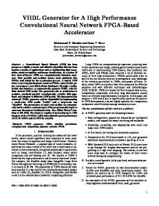
Data
Val Ready
I. I NTRODUCTION Embedded systems are one of the great fields of application for consumer electronics. Their use is widespread in various applications from the automotive field to the domestic appliance. Since they have to be cheap, rich in features and designed with a short time-to-market, their development phase is difficult. Usually these constraints are achieved using highlevel co-design tools. Two problems of such systems are becoming more and more important: (i) power consumption, which is one of the great issue in portable devices, (ii) electromagnetic emissions related to the clock switching activity. These two problems can be faced using self-timed systems [1], which can achieve a reduction in both energy consumption and electromagnetic emissions (EME) [2]. We extend CodeSimulink [3], [4], [5], a co-design environment originally developed for synchronous systems, to clockless logic, in order to fill the lack of asynchronous tools for embedded systems. This paper is organized as follows. Sec. II introduces asynchronous systems while Sec. III describes their implementation in CodeSimulink. Sec. IV describes VHDL code generation and optimization for FPGAs. Sec. V talks about the high-level simulation of such systems. The last section lists future steps in our work. II. S ELF -T IMED C IRCUITS
AND
E MBEDDED S YSTEMS
Self-timed circuits [1] are a special class of digital circuits which do not use one or more global clock signals to generate a timing reference. Each circuit part synchronizes with the others using a handshake protocol. Through handshaking each data producer can signal the validity of its output data while, on the other hand, each data consumer can signal the acquisition of its input data. There are two different types of self-timed circuits concerning data encoding: single-rail (or bundled data) and dualrail [1]. Single-rail systems are a sub-category of asynchronous
Data Signals
Previous Stage
Abstract—This paper introduces a methodology for using selftimed logic in FPGA-based embedded systems starting from a high-level specification of data-flow networks. It uses CodeSimulink as an environment for code generation. The asynchronous circuits are synthesized using conventional commercial tools and we propose solutions for the issues raised. Also we describe a simple way of simulating these designs.
Data−path
Controller
Next Stage Data
Val Ready
Handshaking Signals
Fig. 1.
A single-rail implementation of asynchronous circuits
systems which use some delay lines on the handshaking signals to mimic the path of the data through the data-path module and to ensure the satisfaction of timing constraints (see Fig. 1). Dual-rail, instead, uses the duplication of the same data-path (the actual function and its complementary) and then sends each valid data bit encoded on 2 bits. We choose single-rail approach since it uses less area than the other. The drawback of such method is it relies on delay matching: if the paths of data and of handshaking signals are not the same, some timing violation can occur. Self-timed circuits are moving from research field to commercial one [6], [7] due to several reasons: (i) modularity, (ii) reduced energy consumption, (iii) tolerance to environmental variation (i.e., power supply voltage and temperature, (iv) lower electromagnetic emissions. Unfortunately on FPGAs this is still far from becoming a widespread design methodology due to the fact that the few tools available are mainly for ASIC. The lack of an asynchronous flow for FPGAs and the higher growth of FPGA-based application with respect to the DSP-based one [8] justifies the effort for considering also asynchronous circuits for FPGAs. III. C ODE S IMULINK A PPROACH In our work we aim to use an high-level design tool in order to reduce the time-to-market, which is one of the most important aspects in embedded systems development. One of R the most used methodology is to start from a Simulink model and convert it in an HDL language for the final synthesis [9], [10], [3]. CodeSimulink is a tool developed by our group and offers some advantages (see Sec. III-A) with respect to the other environments.
DATAIN(0)
R uses a Synchronous Data-flow [11], in which Simulink the designer statically specifies the scheduling. The scheduling analysis ensures the correct execution order according to the data dependencies of each elaboration unit. R as simulation engine, we have to Since we use Simulink use the same formalism in actually implementing the model. R (i.e., Xilinx’s Other tools which are based on Simulink System Generator [9]), are actually not consistent with such model, since they ignore the validity of a datum before processing it. CodeSimulink, instead, is fully compatible with the model. To obtain the same behavior of synchronous dataflow in hardware, each signal has associated to its value an information of validation. This information is related to a signal. Such signal is asserted when the producer has generated a new datum and it is removed when the consumer has processed such datum. CodeSimulink is an environment which can generate both VHDL-code for digital hardware (using an internal compiler) and C-code for software (through The Mathworks’ Real-Time R model. It is Workshop compiler) starting from a Simulink composed by:
DATAIN(1)
Data Processing Block
•
• • • •
an ensemble of blocks libraries characterized by implementation-specific parameters (i.e., data representation, number of pipeline stages, physical addresses. . . ); a VHDL implementation of each of them; a set of Matlab scripts for the synthesis process; the needed interfaces between blocks with different implementations other target-specific files.
All these components are necessary to obtain a complete implementation of the high-level model for both FPGAs and DSPs. B. Asynchronous Architecture CodeSimulink was born for generating synchronous systems, but the data/flow implementation of each block leads to a simple implementation also of asynchronous circuits. Each block translated in VHDL is composed of three parts: one implementing the combinational data-path, one managing the communication protocol and a bank of registers for storing valid data (see Fig. 2). This logical partition allows to different implementation only by changing the protocol manager block. This means that once a CodeSimulink block has been written in VHDL it can be implemented both as synchronous and asynchronous only selecting the desired protocol manager. This results in a great saving of time in developing libraries which is crucial for allowing a short time-to-market. We decided to use a single-rail (bundled data) implementation in order to reduce the area occupation of the final implementation and to ensure the correct delay matching using the static timing analysis after the placement. Now follows a brief description on how the handshaking protocol works and how multi-dimension data are managed.
DATA_ELAB
A. Data-flow Model
FF
DATAOUT
P_EN DATAIN_VAL DATAIN_RDY
DATAOUT_VAL
Asynchronous Protocol Manager
DATAOUT_RDY
Fig. 2. The structure of an asynchronous block synthesized by CodeSimulink
DATAIN(0)
Valid Data
Not Valid Data
Valid Data
DATAIN_VAL(0) DATAIN_RDY(0) DATAIN(1)
Valid Data
Not Valid Data
Valid
DATAIN_VAL(1) DATAIN_RDY(1) P_EN DATA_ELAB
Not Valid Data
DATA_OUT
Not Valid Data
Valid Data
Not Valid Data
Valid Data
Not Valid Data
DATA_OUTVAL Elaboration Delay
Next−Block Elaboration Delay
DATA_OUTRDY
Fig. 3.
4-phases handshaking protocol
1) The 4-Phases Handshaking Protocol: literature [1] presents several handshaking protocols, which they can be grouped in two main category: the 2-phase and the 4-phase ones. The former has the advantage of less timing overhead, but on the other side its implementation requires more gates. For this reason we chose to use the 4-phase protocol in our approach. Fig. 3 shows the sequence diagram for the 4-phase implementation used in our approach. When an input datum is ready, its input validation signal (DATAIN VAL(i)) is raised. When all of them are ready a global validation signal is asserted. This signal is delayed by an asymmetric delay line [12] for reflecting the critical path delay in the combinational block. This generates the pipeline enable signal (P EN), which triggers the register bank. Once data have been processed and correctly stored, two different operations are performed: the handshaking closure for the previous block and the handshaking opening for the next block. The former is performed by raising the DATAIN RDY signal, which will fall again after the previous module will have removed DATAIN VAL. The latter is performed asserting the validation signal for the output data (DATAOUT VAL). R 2) Multi-Dimensional Data Management: Simulink manages multi-dimensional data as vectors and matrices. In order to maintain the compatibility with the simulation environment, CodeSimulink realizes an actual implementation which supports 1- and 2-dimensional arrays in both implementations (synchronous and asynchronous). Other similar tools also support multi-dimensional data as an array of bits. CodeSimulink, instead, treats them as an atomic entity as in
E_IV
E_OV
ARRAY MANAGEMENT
E_IM
E_OM DATAOUT_RDY
DATAIN_VAL(0) DATAOUT_VAL RIN C
RINT
A
C
C
DATAIN_VAL(n−1)
DATAIN_RDY
Fig. 4.
P_EN
Brief overview of protocol manager’s structure
R are. To correctly process such data some signals Simulink have been introduced in the protocol manager block. These signals are: • “end of input vector” (E IV) and “end of input matrix” (E IM) used to signal when the last element of a multidimensional structure is arrived; • “end of output vector” (E OV) “and end of output matrix” (E OM) signal the consumer block that the present value is the last element of the multi-dimensional structure.
IV. C ODE G ENERATION AND O PTIMIZATION When we try to synthesize an asynchronous circuit using a standard synthesis tool, we have to face several problems due to the different nature of these designs. The major issues can be listed as follows: • unwanted optimization of the circuit, which can change the expected delays and also the behavior of the final circuit (especially referring the delay lines in the protocol block); • delay line generation, which has to match the delay of the data processing module; • interaction with other peripherals, that can be either synchronous or asynchronous (using another protocol). The first issue can be faced using special synthesis directives [13] in order to prevent this unwanted behavior. The second issue is usually resolved using post-layout delay insertion [14] or using special synthesis directives. The last issue, instead, is similar to the problem of synchronization between different “clock domains”. The following discussion describes how such problems have been resolved in our approach. A. Data-path Block A great advantage of CodeSimulink architecture is that it allows for high modularity. Each part showed in the Fig. 2 has a well-defined interface to the other parts. In this way a change in one of the parts (which respects the interfaces) does not affect the other sub-modules. For example in our case the function of the data processing block still remains the same as the synchronous counterpart, since no changes are needed inside it. The only change needed is on the external driving of its registers. This signal in the asynchronous implementation is not global, but locally generated.
Thus, the modular nature of CodeSimulink permits to perform the really necessary changes only on the desired blocks without affecting the whole system. B. Protocol Block The protocol block has to perform the following operations: 1) to collect all the validation inputs and generate a output signal (R IN) which rises when all inputs rise and falls when all the inputs fall; 2) to delay the protocol signals (R IN⇒R INT), long enough to maintain the temporal consistency between data and protocol signals; 3) to correctly manage the handshaking protocol to ensure a correct block behavior. Fig. 4 depicts the typical implementation of a protocol manager. In this figure, there are some gates and circuit elements not usually present in synchronous circuits, the asymmetric delay line (marked by A) and M¨uller C-element (C). 1) M¨uller C-Elements: a standard M¨uller C-element is a special gate which changes its outputs only when the inputs are all ones or all zeros. Its function is to collect all VAL input signals and generate one validation signal only when all the input data are valid. One implementation, for a 2-input case, is shown in Fig. 5(a). If more inputs are needed, a cascade of such blocks can be automatically generated. In our controller we also needed two other versions of Celements, negative and positive. The negative (Fig. 5(c)) has an input signal, marked with “−”, which is considered only when setting the output to zero. The positive (Fig. 5(b)) considers the “+” input signal only for setting the output to one. Each such gate has fit into one FPGA cell i.e., it has only one output and at most four inputs (feedback lines included). Furthermore the VHDL code has been tagged by special synthesis directives to prevent any optimization by the synthesizer. In this way it is possible to map each C-element onto a FPGA cell, also ensuring their correct behavior. We wrote each M¨uller element as different entity and we put a noopt attributes in each of them in order to avoid the synthesizer (Leonardo Spectrum [13]) optimization that can change the entity behavior. 2) Asymmetric Delay Lines: when a validation signal is generated, it has to be delayed in order to maintain the timing relationships with the data it refers to. So it is necessary to introduce a delay greater than or equal to the critical path of the processing block. On the other side, when the validation signal is lowered it is not necessary to have such a long delay since the operation is already concluded and any delay is an overhead. For these reasons we have to insert an asymmetric delay line which delays only the rising transition and not the falling one. As previously mentioned, since the signal should pass unchanged through the delay line, we use special synthesis directives in order to avoid any synthesizer optimization. (As in the case of the M¨uller C-element, we use the noopt attribute to force synthesizer behavior.)
CLEAR
CLEAR A B
CLEAR
CLEAR A
Y
A B
C
A
Y
C
Y
Y
(a)
(b)
CLEAR
CLEAR A B
C
Y
A B
Y
A X
(c)
X XD
XD
(d)
Fig. 5. Implementation of typical asynchronous gates used in CodeSimulink: standard M¨uller C-element C-element (a), positive (b), negative (c) and the asymmetric delay line(d)
TABLE I S YNTHESIS RESULTS FOR A 8- TH ORDER IIR FILTER
C. Interfaces Interfacing synchronous and asynchronous blocks can lead to the problem of metastability [12]. Avoiding metastability entirely is impossible, we can only reduce the probability of having such a phenomenon. In order to resolve the metastable condition a couple of registers has been inserted between each port interconnecting asynchronous and synchronous blocks [15]. V. H IGH -L EVEL S IMULATION Once we have developed a model using CodeSimulink, the R behavioral simulation can be performed using Simulink engine. In order to check the correctness of the asynchronous blocks, given the delays introduced by physical implementation, we can do the simulation of the synthesized VHDL model. For this reason we have developed an automatic test-bench R simulations generator which converts high-level Simulink into a low-level VHDL test-benches. This test-bench manages both the data and the protocol signals generation. The simulation is performed using a standard tool and the results are saved onto a file. At the end of this R and displayed process, such a file is reloaded in Simulink with the high-level results. In this way we can check the correct behavior of the actual implementation. VI. R ESULTS , F UTURE W ORKS
AND
C ONCLUSION
This work has presented the CodeSimulink approach to the automatic code generation for describing self-timed circuits for embedded systems based on FPGAs. It has described how the code is generated, how it is constrained to avoid synthesis optimizations not suited to asynchronous circuits and how to perform a simple simulation of such systems automatically. Now the automatic generation of self-timed circuits starting R models, is complete, but the calculation of from Simulink delay lines is not yet automatic. Comparing the reports given by the synthesizer for a very simple design (a 16 bit-wide 8th-order IIR filter) for the synchronous and the asynchronous versions, we have an area overhead of about 25% in the latter case mostly given by the delay elements (see Table I).
Cells Registers
Synch. 849 427
Asynch. 1034 621
We are looking towards improvements on achieving more efficiency in synthesis, simulation and implementation. Finally it will be necessary to prepare a study case to test the whole process onto a real embedded system and to compare the properties of the asynchronous implementation versus the synchronous one. R EFERENCES [1] J. Sparso and S. Furber, Principles of Asynchronous Circuits Design. Kluwer Academic Publishers, 2001. [2] C. V. Berkel, M. Josephs, and S. Nowick, “Scanning the technology,” Proceedings of the IEEE, vol. 87, no. 2, February 1999. [3] L. Reyneri, F. Cucinotta, A. Serra, and L. Lavagno, “A hardware/software co-design flow and ip library based on simulink,” DAC, June 2001. [4] E. Bellei, E. Bussolino, F. Gregoretti, L. Mari, F. Renga, and L. Reyneri, “Simulink-based codesing and cosimulation of a common-rail injector test bench,” Journal on Computer, Systems and Circuits, vol. 12, pp. 171–202, 2003. [5] L. Reyneri et al. Codesimulink reference manual. [Online]. Available: http://polimage.polito.it/groups/codesimulink.html [6] H. van Gageldonk, K. van Berkel, A. Peeters, D. Baumann, D. Gloor, and G. Stegmann. An asynchronous low-power 80C51 microcontroller. [7] Handshake-Solutions. ARM996HS product brief. [Online]. Available: http://www.handshakesolutions.com/assets/ downloadablefile/ ARM996HS leaflet feb06-13004.pdf [8] EETimes. (2006, November) FPGAs can outperform DSPs, says study. [Online]. Available: http://www.eetimes.com [9] Xilinx. System generator. [Online]. Available: http://www.xilinx.com/ise/optional prod/system generator.htm [10] Altera. DSP-Builder. [Online]. Available: http://www.altera.com/products/software/products/dsp/dsp-builder.html [11] E. A. Lee and T. M. Parks, “Dataflow process network,” Proceedings of the IEEE, vol. 83, no. 5, May 1995. [12] C. L. Seitz, “System timing,” in Introduction to (VLSI) Systems, C. A. Mead and L. A. Conway, Eds., 1980, ch. 7. [13] M. Graphics. (1999) Leonardo Spectrum HDL synthesis. [14] J. Cortadella, A. Kondrayev, L. Lavagno, and C. P. Sotiriou, “Desynchronication: Synthesis of asynchronous circuits from synchronous specifications,” vol. 25, no. 10, October 2006. [15] R. Ginosar, “Fourteen ways to fool your synchronizer,” Proceedings of the Ninth International Symposium on Asynchronous Circuits and Systems, 2003.