International Journal of Innovative Computing, Information and Control Volume 3, Number 2, April 2007
c ICIC International °2007 ISSN 1349-4198 pp. 247—256
AUTOMATIC HUMAN FACES MORPHING USING GENETIC ALGORITHMS BASED CONTROL POINTS SELECTION Stephen Karungaru, Minoru Fukumi and Norio Akamatsu Department of Information Science and Intelligent Systems University of Tokushima 2-1, Minami Josanjima, Tokushima 770-8506, Japan
[email protected]
Received June 2006; revised September 2006 Abstract. In this paper, a genetic algorithm guided control point extraction method that enables automatic face image morphing is proposed. This method can morph two face images by automatically detecting all the control points necessary to perform the morph. A face detection neural network, edge detection and medium filters are employed to detect the face position and features. Five control points, for both the source and target images, are then extracted based on the facial features. A triangulation method is then used to match and warp the source to the target image using the control points. Finally, color interpolation is done using a color Gaussian model that calculates the color for each particular frame depending on the number of frames used. A real coded Genetic Algorithm (GA) is used to aid the facial features extraction by overcoming size and orientation changes. We achieve very high quality morphs at high speed. Keywords: Genetic algorithms, Morphing, Warping, Neural networks, Face detection
1. Introduction. Morphing technology was made famous by James Cameron’s movie the ”Terminator”, and by the Michael Jackson’s ”Black or White” music video. How was it done? How long did it take to do it? Many people were puzzled. Image metamorphosis, or morphing for short, is commonly referred to as the animated transformation of one image to the other. Image morphing finds numerous applications in many fields including computer vision, animation, art and medical image processing. To morph images, three processes are required; control points extraction, image warping and color transition. Image warping can be defined as a method for deforming a digital image to different shapes. Practically, this can be simulated using an image drawn on an elastic surface. By moving the corners of the elastic material to new positions, the image will deform accordingly. During the morphing process, the number of intermediate images must be decided before hand, and then new positions and color transition rates for the pixels in each of the images in the sequence must be calculated. The processes of feature extraction, warping and color transition [1] involved in morphing proceed concurrently. The control points are similar features in the two images. After their extraction, warping can then be performed based on the number of intermediate images. However, control points decision is a difficult process that is conventionally performed manually. Warp generation is an algorithm that calculates and transforms the pixels in one image to new positions in 247
248
S. KARUNGARU, M. FUKUMI AND N. AKAMATSU
the other image. After warping, transition control blends in the colors between the two images. Over the years, many methods have been proposed to perform image morphing. Automatic face morphing in animation using RBF networks is proposed by [4]. This work creates a new face from prototypes for animation. Triangulation based methods achieve interpolation through a triangulation of control points by first dissecting the defining space into a number of triangles with the given control points being the corners of the triangle. Each of the resulting triangles is then interpolated independently [5]. Obviously, given any number of control points, many triangulations are possible. To avoid thin, poorly shaped triangles and therefore find the optimal triangulation, Delaunay triangulation [3] is commonly used. Field morphing handles correspondence by means of line pairs. A line of corresponding lines in the source and target images defines a coordinate mapping between two images [2]. The Shepard approach of scattered data uses a weighted average of the data values at the data points, with weights dependent on the distance of the points from the given control point [9]. Other methods include the radial basis functions, nearest neighbor interpolation, inverse distance weighted method etc. A comprehensive study of these methods is available in [1]. Transition control has also received a lot of attention. Originally, cross-dissolve was the color blending method of choice, but this method produced undesirable artifacts referred to as ”ghosts” due to the computed warp function [11]. The main disadvantages of many of the methods mentioned above is lack of automation, thereby taking long periods of time to produce a morph and also the production of undesired artifacts in the morphs. In this paper, we solve these problems using a genetic algorithm based feature extraction method that enables automatic morphing of face images and the use of one-dimension Gaussian function for color transition to produce smooth images. The face features selected as control points are the eyes, nose and the mouth. At first, we extract the face location using a neural network based face detector and then extract the facial features. A triangulation method is used as the warp algorithm while a method based on the Gaussian function is applied in color transition control. The warping method used in this work can also be used to deform images if the source and target images are the same but the control points in the target image are freely chosen. In this case, no intermediate images are produced and therefore transition control is not required. 2. The Morphing Process. In this section, the morphing process proposed in this work is described in detail. Face image morphing problem can be defined as follows: Given two face images, progressively transform one into the other as smoothly and as fast as possible. Three aspects of the problem to be tackled are feature extraction, image warping and color interpolation. The procedures described here, which collectively produce the morph, are control point extraction, warping and color transition control. 2.1. Automatic control points extraction. To smoothly morph images, similar points in the two images must be found. These points are called the transition control points. The choice and number of control points determine how accurately two images can be warped. If many control points are used, a good warp can be achieved. However, a high number of control points will increase the number of triangles created (used in the warping phase explained in Section 2.2) that in turn will reduce the speed of the system
AUTOMATIC HUMAN FACES MORPHING USING GENETIC ALGORITHMS
249
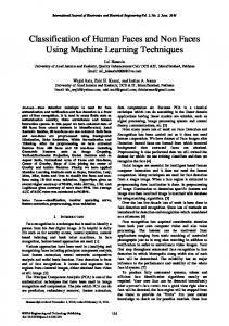
and increase the possibility of poorly shaped and thin triangles. Note that this work focuses on the warping of the human frontal face. Therefore, the control points selected are all within the face region. Five control points, that is, the center of both eyes (C1, C2), the tip of the nose (C3) and both outer corners of the mouth (C4, C5), are consequently defined as shown in Figure 1(a).
Figure 1. (a) Location of the control points (C1-C5). (b) The 32 triangles used for warping. Notice that all the vertices of the triangles can be obtained using the control points and the image size information. Several factors were taken into account before the control points were selected. One is the ability to automatically detect the control points, and two, the guarantee that no poorly shaped or thin triangles are formed. Moreover, the choice is based on the fact that some of their properties, for example, the distances between them, have strong features that can also be used in other face images analysis, for example, face recognition, gesture construction, etc. In addition,, given two faces of different sizes these control points can be used to normalize the faces to a given normal size. The choice of these control points avoids very thin and poorly shaped triangles. Such triangles produce an unnatural looking warp, due to pixel compression [8]. The control points are automatically detected and extracted in each of the two images to be morphed using the processes described below. 2.1.1. Face detection neural network. The control points extraction process begins with the extraction of the face location in each of the two images. This is accomplished using a neural network based face detector. The face detector, referred to as face detection neural network (FDNN) extracts the position of the face from an image [6]. The FDNN consists of a face locator and a genetic algorithm guided search algorithm that takes care of size and orientation changes. The face locator is made up of two parts, a skin color detector and a face detector. Face candidate regions are extracted from an image, as skin color regions, using the skin color detector. The skin color detector was implemented using a YIQ color system threshold based method. The face detector is chosen to be a
250
S. KARUNGARU, M. FUKUMI AND N. AKAMATSU
three layered back propagation trained neural network. The size of the training samples was set at 20x20 pixels because experiment showed that both the accuracy of the system and the speed were best using this size. The error back propagation method is used to train the neural network. The system is trained to produce an output of 0.95 for a face and 0.05 for a non-face. Structural learning with knowledge is also used during training to reduce the size of the face locator and therefore improve the overall speed. During testing, a genetic algorithm is used to extract the sample providing the face detector with invariance to the size and orientation of the face. The FDNN used independently has an accuracy of 97% when tested using images having complex backgrounds and including many people per image. In this paper, the test images contain only one face taken on a neutral background. In such a situation, the FDNN’s accuracy is 100%. 2.1.2. Features extraction - Edge extraction. After the face position has been determined, the position of the facial features, and hence the control points needs to be extracted. For all the images, the control point C3, tip of nose, Figure 1(a), is directly determined using skin color detection step of the FDNN as a hole (non-skin color region) at the center of the image. This is based on experience working with the skin color detector. The tip of the nose is always detected as a non-skin color region. To detect the eyes and the lips, edge detection filters are used. Note that, since we are dealing with a known object the rough positions of these features are known. The filters are applied only inside the face regions detected by the FDNN. The first filter applied is the Laplacian of Gaussian, to smooth and detect the edges of the facial features. On one hand, a relatively small 7x7 kernel filter detects all the edges inside the face, but contains a lot of noise, Figure 2 (a). On the other hand, a large kernel (e.g. 15x15) produces better edge detection results, Figure 2(b).
Figure 2. Edge detection results: (a) 7x7 Laplacian of Gaussian filter, (b) 15x15 Laplacian of Gaussian filter, (c) Features extraction. However, the computation time rises exponentially with the size of the kernel. The best trade-off between the detection results and the computation time should be found. After several experiments, the 7x7 kernel, followed by a 3x3 medium filter to remove the noise, were employed. It is worth noting that the two filters selected take less computation time than the 15x15 kernel filter alone. After noise reduction using the medium filter, the edges are grouped together (small regions and areas around the nose, the left and the right bottom corners are ignored). The regions at the top and the bottom are selected
AUTOMATIC HUMAN FACES MORPHING USING GENETIC ALGORITHMS
251
from which the control points C1 (center of the area on top-left), C2 (center of the area on top-right), C4 (bottom area, left-edge’s center) and C5 (bottom area, right-edge’s center) are extracted as described below, Figure 2(c). 2.1.3. Features extraction - Genetic algorithm (GA). Although, we focus on frontal faces, the facial features accurate extraction cannot always be guaranteed. Accurate extraction of the lips and the eyes is vital for smooth morphing. We employ a genetic algorithm to reinforce the results of the segmentation of these features by using a genetic algorithm to assist in the matching of the general shapes of the segmented areas. The general shapes of the eyes and the lips are assumed to be oval. The length of the GA chromosome used is 26. The first five pixels represent the height and the following five, the width of the shapes. The remaining 16 chromosomes represent selected points on the shape of roughly equal distance from each other. The size of the shape can thus be reduced or increased to fit the size of the segmented region. The genetic algorithm processes of reproduction crossover and mutation are described below. During reproduction, we use the top 50% of the fittest individuals to reproduce 75% of the next population. The remaining 25% of the next population is reproduced by selection of their parents at random from the initial population. This method improves the search space by ensuring that we not only retain the best individuals for reproduction, but also explore the rest of the population for other possible candidates. The selection of parents is performed using the roulette wheel method. The crossover point is determined depending on the total fitness of the parents. The higher the fitness, the lower, in the chromosome string, the point of crossover is. The fitness function is designed for fast convergence. The fitness function is, (x − xi )2 + (y − yi )2 + F itness = (x + y + z)2
P
(z − zi )2
(1)
where x, (xi ), y, (yi ), z and (zi ) are the height, width and the points selected from the shape (segmented area) respectively. The genetic algorithm is set to terminate after 50 generations or a fixed elite solution for over 10 consecutive generations. 2.2. Warping. Warping is the process that transforms the images by moving the control point locations in one image to match the ones in another. These locations are based on the size of the morphing step used. The smaller the value, the more the intermediate images created. Once these control points have been extracted from the two original images, the images are ready for warping. The source and target images are of the same size, but the faces in them can be of different sizes. The warping method used in this work is the triangles based interpolation. The images are divided into triangles using the control points already found. This results in 32 triangles per image as shown in Figure 1(b). Note that apart from the four corners of the image, all the other points, on the edges of the image, that complete the triangles are all related to the five control points and therefore easy to evaluate. To evaluate the values of these points, all that needs to be known is the size of the image. For two corresponding triangles, one from the source image and the other from the target image, the warping transformation from one to the other can be performed. The triangulation algorithm used is described as follows.
252
S. KARUNGARU, M. FUKUMI AND N. AKAMATSU
Let points P1 , P2 and P3 on the source image be located at x1 = (u1 , v1 ), x2 = (u2 , v2 ) and x3 = (u3 , v3 ) respectively. Also let points Q1 , Q2 and Q3 on the target image be located at y1 = (x1 , y1 ), y2 = (x2 , y2 ) and y3 = (x3 , y3 ) respectively. The points on the source image can be mapped to those on the target image using Eqs.(2) and (3). x = a11 u + a21 u + a31 y = a12 v + a22 v + a32
(2) (3)
These two equations can be written in matrix form as follows using the points at x1 −x3 and y1 − y3 , Eq.(4). ⎡
x 1 y1 1
⎤
⎡
a11 a12 0
⎤⎡
u1 v1 1
⎤
⎢ ⎥ ⎢ ⎥⎢ ⎥ ⎣ x2 y2 1 ⎦ = ⎣ a21 a22 0 ⎦ ⎣ u2 v2 1 ⎦ x 3 y3 1 a31 a32 1 u3 v3 1
(4)
The coefficients a11 , a12 , a21 , a22 , a31 and a32 can be found by solving the equation below. ⎡ That is,
a11 a12 0
⎤
⎡
x 1 y1 1
⎤⎡
u1 v 1 1
⎤−1
⎢ ⎥ ⎢ ⎥⎢ ⎥ ⎣ a21 a22 0 ⎦ = ⎣ x2 y2 1 ⎦ ⎣ u2 v2 1 ⎦ a31 a32 1 x 3 y3 1 u3 v 3 1 A = CD −1
(5)
(6)
Note that, the inverse matrix D−1 will exist if and only if the determinant |D| 6= 0, since this is a square matrix [7]. Warping can then be performed using target to source mapping. We use the target to source approach because no pixels on the target image are missed and therefore no color interpolation is necessary. The effect of warping on a given face image is shown in Figure 3. In this figure, the objective is to transform the facial features in Figure 3(a) to the location of the ones in Figure 3(b). The Figures 3(c)-(g) shows the warping sequence. Notice that, the locations of the facial features of Figure 3(a) have been transformed to match those of Figure 3(b) as shown in Figure 3(g). Since the facial features in the images in Figure 3(b) and Figure 3(g) match, color transition between the two images will produce a smooth morph with very little undesired artifacts. 2.3. Color transition. A morph contains a sequence of intermediate images between the source and the target image. Color transition is the method that determines the rate of color blending across the sequence. The choice of this rate determines the quality of the morphs. Interesting morphs can be created depending on whether the color-blending rate changes locally or globally. The rate of color blending is usually based on weights. Such weights are selected to smoothly complete the transition between the images on the sequence. In this paper, the weights are calculated using a one-dimension Gaussian function. This method is implemented as follows: Given two corresponding target and source
AUTOMATIC HUMAN FACES MORPHING USING GENETIC ALGORITHMS
253
pixels, first, calculate the difference in color between them and then set the Gaussian function to 1 for the target pixel and to 0 for the source image.
Figure 3. Face features warping example (a) Source, (b) target, (c)-(g) images created in each warping step. The weight for each morph in the sequence is then calculated based on the color difference calculated before, the value of the Gaussian function at that point and the number of warps in the sequence. The color for each image in the morph sequence is then; Ψj = Ψi − ωi ∗ ∆ωij
(7)
where Ψj is the color for the new warped pixel, ωi is the weight and ∆ωij is the color difference between the target and source pixels. This procedure is repeated for every pixel in the image and for every image in the morph sequence. The source image changes from the original image, to the new image produced by the first warp and so on. 3. Results and Discussion. The images used in this work were acquired from the physics based face database of the University of Oulu [10]. The size of all the images is 640x480 pixels. 3.1. Morphing procedure. The morphing algorithm proposed in this work proceeds as follows: 1. Input the source and target face images. 2. Detect the face position in each image using the FDNN. 3. Extract the facial features using edge extraction and the genetic algorithm. 4. Calculate the separation between like features in the two images and then calculate the warping step. Warp the images, Figure 3. 5. After warping, the facial features in both images are matched. Calculate the morphing step based on the matching pixel color difference and perform color transition.
254
S. KARUNGARU, M. FUKUMI AND N. AKAMATSU
3.2. Results. The results of morphing are shown in Figure 4. Figure 4(a) is the source image and Figure 4(b) is the target image. 13 intermediate images (b)-(n) were produced. Images (b)-(e) are the results of warping as described in Section 2.2. The images (f)-(n) are created using the color transition control. Notice the smoothness of the face regions. Also note that halfway through the morph, images (h)-(j), faces of completely different persons are created.
Figure 4. Morphing sequence: (a) source, (o) target. Images (b)-(e) are the results of warping as described in Section 2.2. The images (f)-(n) are created using the color transition control. The warping method discussed in Section 2.2 can be used independently to freely deform images using one, all or any combination of the control points. During warping, the source and target images are the same. Moreover, no intermediate images are produced, as is the case with morphing. Figure 5 shows some of the images produced by the warping function. As Figure 5 shows, by arbitrarily moving the control points inside the face region, face image deformation is possible. This work was carried out using a Dell Optiplex Sx260 512MB personal computer. Face detection and control points extraction took about 2.01 seconds, while warping took 0.11 seconds to complete.
AUTOMATIC HUMAN FACES MORPHING USING GENETIC ALGORITHMS
255
Figure 5. Image warping: (a) source, (b)-(e) warped images using arbitrary selected positions for the control points. 3.3. Discussion. Five control points were automatically extracted to control the morph. The control points were all selected from inside the face. This offers the advantage of morphing the face regions very smoothly. However, as the distance from the control points increase, the creation of shadows is apparent, especially around the hair regions. While skin color regions can be detected accurately for different people, hair regions cannot due to different hair colors and complex backgrounds. Using the Gaussian function as the color transition control increases the amount of computation time required, but has the advantage of producing better morphs. One other method tried was to use a constant color transition rate (equal percentage increments) on all the images based on the number of images in the morph. While this ran a little faster than the Gaussian function method, its results were not visually better. 4. Conclusion. This paper proposes a method to automatically morph face images using automatic control points extraction. The results show that the method produces smooth morphs using only 15 frames. Moreover, the ability of the warping method to deform images is demonstrated. This work uses only five control points to achieve a good result for the face region. These control points are extracted automatically, which reduces the parameters that must be inputted by the user. The time taken to produce a morph is 2.01 seconds. This includes the time taken to load the image to and from memory. Warping process took only 0.11 seconds. Future works include, the increase of automatically detectable control points to reduce the undesired artifacts around the subject’s hair region and background. Color transition algorithm will also be improved so that the number of frames required to complete the morph are reduced. The warping and color transition steps also need to be automatically decided so that the morphing can be improved further. REFERENCES [1] Amidror, I., Scattered data interpolation methods for electronics imaging systems: A survey, Journal of Electronic Imaging, vol.11, no.2, pp.157-176, 2002. [2] Beier, T. and S. Nelly, Feature-based image metamorphosis, Proc. of the SIGGRAPH, pp.35-42, 1992. [3] Berg, M., M. Kreveld, M. Overmars and O. Schwarzkorf, Computation Geometry Algorithms and Applications, Springer, 1997. [4] Bui, D., M. Poel, D. Heylenand and A. Nijholt, Automatic face morphing for transferring facial animation, Proc. of the IASTED Conference on Computer Graphics and Imaging, pp.19-24, 2003.
256
S. KARUNGARU, M. FUKUMI AND N. AKAMATSU
[5] Goshtasby, A., Piecewise linear mapping functions for image registration, Pattern Recognition, vol.19, no.6, pp.459-466,1986. [6] Karungaru, S., M. Fukumiand and N. Akamatsu, Genetic algorithms based on-line size and rotation invariant face detection, Journal of Signal Processing, vol.9, no.6, pp.497-503, 2005. [7] Lipschutz, S., Invertible Matrices, — Schaum’s Outline of Theory and Problems of Linear Algebra, 2nd ed., New York: McGraw-Hill, 1991. [8] Nielson, G., H. Hager and H. Muller, Scientific Visualization, IEEE, New York, 1997. [9] Rurecht, D. and H. Muller, Free form deformation with scattered data interpolation methods, Geometrical Modeling, pp.267-281, Springer Verlag, 1993. [10] Soriano, M., E. Marszalec and M. Pietikainen, Color correction of face images under different illuminants by RGB eigenfaces, Proc. of the 2nd Audio- and Video-Based Biometric Person Authentication Conference, pp.148-153, 1999. [11] Worlberg, G., Image morphing: A survey, The Visual Computer, vol.14, pp.360-372, 1998.