Automatic Merge-point Detection for Sequential Equivalence Checking of System-level and RTL Descriptions Bijan Alizadeh1, and Masahiro Fujita1 1
VLSI Design and Education Center (VDEC), University of Tokyo, Japan
[email protected],
[email protected]
Abstract. In this paper, we propose a novel approach to verify equivalence of C-based system level description versus Register Transfer Level (RTL) model by looking for merge points as early as possible to reduce the size of equivalence checking problems. We tackle exponential path enumeration problem by identifying merge points as well as equivalent nodes automatically. It will describe a hybrid bit- and word-level representation called Linear Taylor Expansion Diagram (LTED) [1] which can be used to check the equivalence of two descriptions in different levels of abstractions. This representation not only has a compact and canonical form, but also is close to high-level descriptions so that it can be utilized as a formal model for many EDA applications such as synthesis. It will then show how this leads to more effective use of LTED to verify equivalence of two descriptions in different levels of abstractions. We use LTED package to successfully verify some industrial circuits. In order to show that our approach is applicable to industrial designs, we apply it to 64point Fast Fourier Transform and Viterbi algorithms that are the most computationally intensive parts of a communication system. Keywords: Formal Verification, Sequential Equivalence Checking, System on a Chip (SoC), Communication System, Canonical Representation.
1 Introduction As system on a chip (SoC) designs continue to increase in size and complexity, many companies have paid more attention to design hardware at higher levels of abstraction due to faster design changes and higher simulation speed. In this phase, a C-based high level specification is described and then refined to a Register Transfer Level (RTL) description by adding more and more implementation details at different steps. Therefore there is a significant increase in the amount of verification required to achieve functionally correct description at each step, if traditional dynamic techniques such as simulation are used. This has led to a trend away from dynamic approaches and therefore Sequential Equivalence Checking (SEC) methods have become very important to reduce time-to-market as much as possible. SEC is a process of formally proving functional equivalence of designs that may in general have sequentially different implementations. Examples of sequential differences span the space from retimed pipelines, differing latencies and throughputs, and even scheduling and resource allocation differences. A few approaches have been proposed to perform equivalence checking between C-based specification and RTL description. In symbolic simulation based approaches,
loop and conditional statements need to be unrolled and then all paths through the code must be explored [2-7]. If dependencies exist between different iterations of a loop statement, it will increase the run time for symbolic simulation and degrades quality due to the exponential number of paths. For example consider C code of Fig. 1(a). After unrolling for-loop, corresponding to each then and else branch it is necessary to have two execution paths. In general for N number of iterations we have to enumerate 2N paths and therefore exponential path enumeration problem occurs. On the other hand, the different results computed on the different paths must be tracked that will cause a blow-up in logic if lower level techniques such as BDDs and SAT solvers are utilized. for (i=0; i B1) AcumErr[nextstate[i][j]][1] = B1; StateHistory[nextstate[i][j]][t] = i; K-1 ; i++) for (i = 0 ; i < 2 AcumErr[i][0] = AcumErr[i][1]; AcumErr[i][1] = MAXINTEGER; Fig. 10. Pseudo code of Viterbi algorithm.
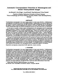
Cut-planes and Merge-points in Viterbi Benchmark. In this section we will discuss how to determine cut-planes and merge-points in the C-based description to reduce the size of equivalence checking problem. In Viterbi decoder the first K stages are different from other stages as shown in Fig. 11(a), where K is 7. This is because during the first K stages, there is only one path to achieve each next state from current state. For instance at t=1, there is only one way to reach next states 0, 16, 32 and 48. These stages are outputs of the corresponding iterations of the outer loop of Fig. 10 that are viable candidates to be cut-planes as illustrated in Fig. 11(a). On the other hand, another decision flow exists for stages K+1 to 6*K-1, where each state can be reachable from two paths. One decision butterfly out of 32 pairs needed for Viterbi decoder K = 7, has been depicted in Fig. 11(b), where S varies from 0 to 31. In this figure each circle indicates a state and also corresponds to an ACS operation in Fig. 10. For instance consider state S that can be received through 2S and 2S+1 by different branch metrics. According to Viterbi algorithm described in Fig. 10, to compute accumulated error metric for this state, first of all AcumErr[2S][0]+BrMetric0 is computed (B1) and then compared to AcumErr[S][1] (A1 of Fig. 10). Finally the smaller one is saved as a new value into AcumErr[S][1]. This process is repeated when B1 = AcumErr[2S+1][0]+BrMetric2 is computed and compared to AcumErr[S][1]. As illustrated in Fig. 10, after completing the second loop nest, AcumErr[S][1] is saved into AcumErr[S][0] and gets a very large integer
number, i.e., MAXINTEGER, because of beginning another iteration of an outer loop properly (see the fourth loop in Fig. 10). Obviously, each output of ACS units has the potential to be a merge point due to conditional statements. 0
0
0
0
16
…
BrMetric0
0
2S
8
1
16
2
24
3
S
BrMetric1 BrMetric2
32
32
…
…
32
2S+1
40 62 48
48 63 56
Cut-plane t=0
t=1
t=3 (a)
Stage (t-1)
Stage (t) (b)
…
Cut-plane
t=2
S+32 BrMetric3
Cut-plane …
t=6
Fig. 11. (a) Seven first stages of Viterbi K=7 (b) Decision butterfly for ACS pair in Viterbi K=7.
Experimental Results. Table 3 provides experimental results for six configurations of Viterbi decoder, i.e., Viterbi (K=3) without merge point detection (Vitbi3nomp), Viterbi (K=3) with merge point detection (Vitbi3mp), Viterbi (K=7) with merge point detection (Vitbi7mp), Viterbi (K=7) with merge point and cut-plane detection (Vitbi7mpcp), Viterbi (K=9) with merge point detection (Vitbi9mp) and Viterbi (K=9) with merge point and cut-plane detection (Vitbi9mpcp). In this table, rows #Nodes and #Vars give the number of LTED nodes and the number of input variables respectively. The memory usage and CPU time needed for equivalence checking of the two descriptions are presented in rows Mem (in Mega-Byte) and Time (in seconds) respectively. The second and third columns, i.e., Vitbi3nomp and Vitbi3mp, provide useful information before and after applying automatic merge point detection method to Viterbi K=3 test case. Obviously, in this case after finding merge points automatically, 90-24 = 66 new primary inputs (#Vars row in Table 3) have been introduced and the number of LTED nodes (#Nodes) has reduced from 52827 to 355. Moreover, memory and run time required for equivalence checking have been reduced from 36.3 MB to 0.4 MB and 57.8 seconds to 0.1 second respectively. Columns Vitbi7mp and Vitbi7mpcp in Table 3 represent experimental results of Viterbi K=7. Although we are not sure that LTED package is able to handle this case without merge point detection, the task of preparing the input file for this package is very difficult because it needs to duplicate the number of states on each iteration where the number of iterations and the number of states on the first iteration are K*61 = 41 and 2K-1 = 64 respectively. Thus here we only report experimental result of Viterbi K=7 after applying merge point detection technique where memory usage and CPU time required to perform equivalence checking are 6.9 MB and 12.6 seconds. While after defining cut-planes, as shown in column Vitbi7mpcp of Table 3, they have
been reduced to 6 MB and 12 seconds respectively. Fortunately the case study in [2] was Viterbi K=7 that makes it possible to compare results without spending a lot of time to apply Viterbi K=7 to SAT based methods. The authors in [2] have used zChaff as a SAT solver to check the equivalence between expressions computed at every cycle of RTL model and expressions achieved from C-based description. They gave a breakdown of number of clauses in the CNF formula for various blocks. Table 4 provides experimental results of our method in comparison with proposed method in [2]. Although they reported that without their decomposition method, the monolithic Trellis computation would generate a CNF with nearly 1.9 million clauses, after using the decomposed technique, they created 32 independent CNF formulas that were input to zChaff. Each of these formulas had 59136 clauses and 128 variables. In addition the number of clauses in the CNF formula for Trellis computation per butterfly was 57344, while in our method it requires 352 LTED nodes, 0.28 MB memory and 0.06 second run time to check the equivalence between butterflies in the two descriptions. There was no report of memory usage and CPU time for SAT based method proposed in [2], so related entries was left blank in Table 4. The two last columns in Table 3 give experimental results of Viterbi K=9. After applying merge-point technique, in order to verify the equivalence of two descriptions, 66075 LTED nodes was generated and LTED package spent 190 seconds run time while the memory manager reported that 27.3MB RAM was consumed. This case proves scalability of our approach in comparison with method in [2] that was only applied to Viterbi K=7 and it cannot deal with Viterbi K=9 due to computational explosion problem of lower level SAT-based methods. Table 3. Experimental results of Viterbi benchmark. Type
Vitbi3nomp
Vitbi3mp
Vitbi7mp
Vitbi7mpcp
Vitbi9mp
Vitbi9mpcp
#Nodes #Vars Mem Time
52827 24 36.3 57.8
355 90 0.4 0.1
13279 2258 6.9 12.6
12665 2384 6 12
66075 11627 27.3 190
64761 11881 26.5 178
Table 4. Experimental results of Trellis computation per butterfly in Viterbi benchmark. Technique
#Nodes
#Var
Memory (MByte)
Time (Sec)
#add
#sub
Our Method Method in [2]
352 57344
66 66
0.28 ---
0.06 ---
262 ---
8 ---
6 Conclusion and Future Work In this paper, we proposed an automatic merge-point detection technique based on an hybrid bit- and word-level canonical representation called LTED. Then we have used it to check the equivalence between C-based specification and RTL implementation of two large industrial circuits, i.e., 64-point FFT algorithm (FFT64) and Viterbi decoder K=3, 7, 9. This representation is strong enough to handle arithmetic operations at word level representation and there is no need to encode them to bit-level operations. As opposed to low level methods such as Boolean SAT based techniques reported in
the literature, the empirical results indicate that our approach not only uses an efficient canonical form to represent symbolic expressions but also is scalable even on large industrial circuits. Obvious direction for future work is to integrate LTED package with a SpecC environment to address the equivalence checking between different abstractions of SpecC as a system level language.
Acknowledgement This work was supported in part by Semiconductor Technology Academic Research Center (STARC).
References 1.
Alizadeh, B., Fujita, M.: LTED: A Canonical and Compact Hybrid Word-Boolean Representation as a Formal Model for Hardware/Software Co-designs. The fourth Workshop on Constraints in Formal Verification (CFV 2007) 15-29 2. Vasudevan, S., Viswanath, V., Abraham, J., Tu, J.: Automatic Decomposition for Sequential Equivalence Checking of System Level and RTL Descriptions. In Proceedings of Formal Methods and Models for Co-Design (MemoCode 2006) 71-80 3. Feng, X., Hu, A.: Early Cutpoint Insertion for High-Level Software vs. RTL Formal Combinational Equivalence Verification. In Proceedings of 43th Design Automation Conference (DAC 2006) 1063-1068 4. Matsumoto, T., Saito, H., Fujita, M.: Equivalence checking of C programs by locally performing symbolic simulation on dependence graphs. In Proceedings of 7th International Symposium on Quality Electronic Design (ISQED 2006) 370–375 5. Koelbl, A., Lu, Y., Mathur, A.: Embedded tutorial: Formal Equivalence Checking Between System-level Models and RTL. In Proceedings of ICCAD (2005) 965-971 6. Kroening, D., Clarke, E., Yorav, K.: Behavioral Consistency of C and Verilog Programs Using Bounded Model Checking. In Proceedings of 40th Design Automation Conference (DAC 2003) 368–371 7. Karfa, C., Mandal, C., Sarkar, D., Pentakota, S. R., Reade, C.: A Formal Verification Method of Scheduling in High-level Synthesis. In Proceedings of 7th International Symposium on Quality Electronic Design (ISQED 2006) 71–78 8. Fallah, F., Devadas, S., Keutzer, K.: Functional Vector Generation for HDL Models Using Linear Programming and 3-Satisfiability. In Proceedings of 35th Design Automation Conference (DAC 1998) 528-533 9. Alizadeh, B., Fujita, M.: A Hybrid Approach for Equivalence Checking Between System Level and RTL Descriptions. In 16th International Workshop on Logic and Synthesis (IWLS07 2007) 298-304 10. Horeth, S., Drechsler, R.: Formal Verification of Word-Level Specifications. In Proceedings of Design Automation and Test in Europe (DATE 1999) 52-58 11. Alizadeh, B., Navabi, Z.: Word Level Symbolic Simulation in Processor Verification. In IEE Proceedings Computers and Digital Techniques Journal Vol. 151, No. 5 (2004) 356-366 12. Grass, E., Tittelbach, K., Jagdhold, U., Troya, A., Lippert, G., Krueger, O., Lehmann, J., Maharatna, K., Fiebig, N., Dombrowski, K., Kraemer, R., Aehoenen, P.: On the Single Chip Implementation of a Hiperlan/2 and IEEE802.11a Capable Modem. In IEEE Pers. Commun., Vol. 8 (2001) 48–57