Automatic Model Driven Animation of SCR Specifications Angelo Gargantini1 and Elvinia Riccobene2 1
2
C.E.A.- Università di Catania
[email protected] Dipartimento di Matematica e Informatica - Università di Catania
[email protected]
Abstract This paper introduces automatic model driven animation, a novel approach to validate requirements specifications. This approach, here applied to SCR specifications, is based on graphical animation. Automatic model driven animation consists in automatically deriving scenarios from requirements specifications; these scenarios are used to animate critical system behaviors through a graphical interface. Animation is useful at the very early stages of systems development to better understand models and requirements, to gain confidence that specifications capture informal requirements, and to detect faults. We introduce a technique, exploiting model checkers, to automatically generate animation sequences starting from requirements specifications, and we present a prototype tool for the generation and animation of scenarios.
1
Introduction
Many methods, techniques, and tools are continuously proposed to analyze, validate, and verify formal specifications. Several methods deal especially with validation of formal specifications. The validation activity can be summarized by the well known question “Are we building the right system?” and it consists in checking whether the system, as specified, meets the user needs. Techniques for validation include scenarios generation, development of prototypes, simulation, and also testing [17,7]. These techniques can help designers and customers to better understand models and requirements, to gain confidence that specifications capture informal requirements, and to detect faults in specifications as early as possible with limited effort. Validation should precede the application of more expensive and accurate methods, like formal requirements analysis and formal verification of properties [8], that should be applied only when designers have enough confidence that specifications are correct. To be effective, the validation activity should be supported by tools easy to use and requiring minimum user effort. This paper introduces automatic model driven animation as a novel approach to validate requirements specifications. This approach, here applied to SCR (Software Cost Reduction) specifications [13], is useful at the very early stages of systems development, and it is based on graphical animation (hereinafter briefly called animation) [10,16,19]. Animation basically consists of simulation, providing the user with a graphical interface suitable to show the state of the system by means of icons, buttons, panels, slides, and so on. An animator might be a prototype ad hoc developed or a simulator
endowed with a complex graphical interface. A prototype tool for animation of SCR specifications, is described in this paper. Animation offers several advantages. Mainly, through animation designers better understand the requirements specification and can find failures and faults. For customers, looking at the real behavior shown by the animator is better than reading mathematical or logical formulas modeling the system behavior (normally customers do not like mathematical formalisms). Customers can ignore in which notation the specification has been written and they do not need to learn new (formal) languages. Animation, especially as proposed in this paper, does not require skills, ingenuity and expertise as those required by heavy formal methodologies like theorem proving. However, animation cannot prove that a specification is correct, but it can only uncover faults [21]. For this reason, it is very similar to testing. The main problem of animation is the selection of system behaviors to animate. We distinguish three main ways for selecting scenarios: 1. user driven animation: users (customers or designers) “play” with the animator and check whether the specification meets customers needs or not. Users select inputs, regardless the specification, by means of buttons, slides, and graphical elements; outputs are computed according to the specification (that acts as oracle) and shown by means of other graphical elements. Except for the graphical interface, this approach is very similar to the classical simulation. 2. random animation: inputs are randomly generated taking into account only their specified constraints. Outputs are computed according to the specification and shown through the graphical animator. In this case, the user observes the system behavior and judges its correctness. This approach is proposed in [22]. 3. model driven animation: inputs are selected starting from requirements specifications in a systematic way, either manually or automatically. The former is similar to case 1, but the specification is used as guideline. The latter is the new approach proposed in this paper. In any of these three animation approaches, the judgment of the specification correctness is left to the human; however, the effort required substantially differs, and model driven animation is more efficient than user driven or random animation for several reasons. By animation, designers gain confidence that the specification is correct only if the model has been extensively simulated and enough scenarios have been checked. Therefore, performing a good selection of critical scenarios, that can uncover specification faults, is crucial. Since random animation produces a huge amount of scenarios, the careful review of all the behaviors is time consuming. Furthermore, only few generated scenarios are able to expose critical faults. In user driven, as well as in manual model driven animation, designers have the responsibility to cover all the critical behaviors. Since selection is carried out by hand, they risk to leave out some particular cases and choose only a small subset of all the specified behaviors. The manual selection of scenarios is, therefore, expensive and error-prone, especially in user driven animation, where specifications are not used as guidelines. Automatic model driven animation, here introduced, has the advantage to automatically derive scenarios from specification, and to assure the animation of all the critical
behaviors according to the requirements. It does not require great user skill and ingenuity and is an effective approach for model validation. Besides selection of critical scenarios, another critical issue is the actual graphical animation of the generated scenarios. This requires a tool endowed with a graphical animator panel that reproduces the look and feel of the real system under animation. This verisimilar environment is of great help to customers: they do not have to learn a new environment (like a new tool or IDE or interface), they do not watch variable values only by means of digits or strings (like in debuggers), they do not have to query system state by typing commands, and they do not need to guess the meaning of the values in terms of system behaviors. To be effective, animator panels must be constructed and modified rapidly, accurately, and cheaply. They do not have to be efficient, complete, portable, or robust and they do not have to use the same hardware, software, or implementation language as the delivered system. An animator panel should have two kinds of components: static components, as background images, logo, and frames, that do not change their aspect during simulation, and dynamic graphical components that change their aspect (color, size, or shape) according to variable changes, showing the system evolution. In this way, the user can watch the system as he/she were just in front of the real system. A real example of animator panel for SCR can be found in [11], where a complex graphical front-end of a simulator is developed to simulate an aircraft cockpit. In this work, we also present the software architecture of an animator tool endowed with an animator panel compliant with these requirements. The paper is organized as follows. Section 2 introduces the formal method SCR and proposes a case study we will use to illustrate the novel approach and the animator prototype. Automatic animation for SCR specifications is presented in Section 3. We explain how to automatically compute from SCR specifications scenarios assuring the animation of all the critical behaviors. Section 3.3 introduces an interesting variant of automatic model driven animation, called animation on demand. In Section 4, a prototype tool for automatic animation of SCR specifications is presented. Related work is discussed in Section 5, while conclusions and future work are presented in Section 6.
2
Software Cost Reduction Technique
The Software Cost Reduction (SCR) [13] is a set of techniques for designing software systems developed by David Parnas and researchers from U.S. Naval Research Laboratory (NRL). SCR offers several automated techniques, supported by a tool set [11], for detecting errors in software requirements specifications, including an automated consistency checker to detect missing cases and other application-independent errors [14]; a simulator to symbolically execute the specification to ensure that it captures the users intent; and a model checker to detect violations of critical application properties [1]. 2.1
The Formal Method
The SCR model represents the environmental quantities that the system monitors and controls as monitored and controlled variables. The environment nondeterministically produces a sequence of input events, where an input event signals a change in some
Modes m1 ... mn varCi
Event New mode e1,1 m ¯ 1,1 e1,p e1,p1 m ¯ 1,p1 ... ... .. en,p en,1 m ¯ n,1 vp en,pn m ¯ n,pn Event table Mode table Table 1. Condition, event, and mode table format
Conditions c1,1 c1,2 ... c1,p ... ... ... ... cn,1 cn,2 ... cn,p v1 v2 ... vp
Condition table
Modes m1 ... mn varEi
Event e1,1 e1,2 ... ... ... ... en,1 en,2 ... v1 v2 ...
Old Mode m1 ... ... mn
monitored quantity. The system, represented in the model as a state machine, begins execution in some initial state and then responds to each input event in turn by changing state and by possibly producing one or more output events, where an output event is a change in a controlled quantity. An assumption of the model is that at each state transition, exactly one monitored variable changes value. To concisely capture the system behavior, SCR specifications may include two types of internal auxiliary variables: terms, and mode classes whose values are modes. Mode classes and terms often capture historical information. In the SCR model, a system is represented as a 4-tuple, (S, S0 , E m , T ), where S is the set of states, S0 ⊆ S is the initial state set, E m is the set of input events, and T is the transform describing the allowed state transitions [14]. Usually, the transform T is deterministic, i.e. a function that maps an input event and the current state to a new state. To construct T , SCR composes smaller functions, each derived from the two kinds of tables in SCR requirements specifications, event tables and condition tables. These tables describe the values of each dependent variable, that is, each controlled variable, mode class, or term. Tables have the typical format shown in Table 1. A condition table specifies that the value of the variable varCi is vk if the boolean condition cj,k holds in mode mj . An event table specifies that the variable varEi takes value vk when event ej,k happens in mode mj . Mode tables are a variant of event tables and specify the behavior of mode class: if mode has value mj and event ej,k happens, then mode becomes m ¯ j,k . The SCR model requires the entries in each table to satisfy certain “consistency” and “completeness” properties. These properties guarantee that all of the tables describe total functions [14]. Tabular notation, with an intuitive semantics, facilitates the practical use in industrial applications. In SCR, a state is a function that maps each variable in the specification to a value, a condition is a predicate defined on a system state, and an event is a predicate defined on a pair of system states implying that the value of at least one state variable has changed. When a variable changes value, we say that an event “occurs". The expression “@T(c) WHEN d” represents a conditioned event, which is defined by def
@T(c) WHEN d = ¬c ∧ c0 ∧ d where the unprimed conditions c and d are evaluated in the current state and the primed condition c0 is evaluated in the next state. The expression “@T(c)” means ¬c ∧ c0 , while “@F(c)” means c ∧ ¬c0 .
Old Mode Event New mode TooLow @T(WaterPres ≥ Low) Normal Normal @T(WaterPres ≥ Permit) High @T(WaterPres < Low) TooLow High @T(WaterPres < Permit) Normal Table 2. Mode table defining the Mode Class Pressure of SIS
2.2
An SCR Case Study: the Safety Injection System (SIS)
Case study of this paper is the SCR specification of a system called the Safety Injection System (SIS), a simplified version of a control system for safety injection in a nuclear plant [5], which monitors water pressure and injects coolant into the reactor core when the pressure falls below some threshold. The system operator may override safety injection by turning a “Block” switch to “On" and may reset the system after blockage by setting a “Reset" switch to “On". To specify the SIS requirements in SCR, we represent the SIS inputs with the monitored variables WaterPres, Block, and Reset and the single SIS output with a controlled variable SafetyInjection. The specification also includes two internal auxiliary variables, a mode class Pressure, an abstract version of WaterPres, and a term Overridden which indicates when safety injection has been overridden. The Mode Table 2 specifies the value of Pressure and the Event Table 3 specifies the value of Overridden. The Condition Table 4 specifies the behavior of SafetyInjection. A constant Low = 900 defines the threshold that determines when WaterPres is in an unsafe region, while a constant Permit = 1000 determines when the pressure is high and the system cannot be overridden. Pressure High TooLow, Normal Overridden
Events false @F(Pressure=High) @T(Block=On) @T(Pressure=High) OR WHEN Reset = Off @T(Reset = On) True False
Table 3. Event Table for term Overridden
Since tables specify the function T of transformation from the current state to the next one, they represent operational or functional requirements. Besides these requirements, SCR model introduces system properties in terms of events and conditions that must be true in every state. These properties are safety requirements and represent the declarative requirements of the system. We exploit this distinction in Section 3. For SIS, the property “if pressure becomes too low, safety injection does not turn on if the system is blocked” is a safety requirement expressed in SCR as: @T(WaterPres < Low)WHEN Block = On ∧ Reset = Off → SafetyInjection0 = Off (1)
Pressure TooLow Overridden Normal, High true SafetyInjection Off
Conditions not Overridden false On
Table 4. Condition table for controlled variable SafetyInjection
i.e. if the water pressure falls below Low and Block is On and Reset is Off, then Safety Injection is Off in the next state. This property has been proved in [12].
3
Automatic Model Driven Animation
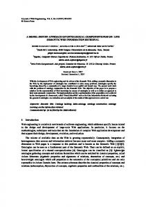
In this section, we tackle automatic model driven animation for SCR specifications. Figure 1 shows the process of generation and animation of critical scenarios. Animation goals, each representing a critical system behavior to animate, are systematically derived from SCR specifications in an automatic way. Scenarios achieving the animation goals are computed by exploiting the counter example generation of model checkers. Finally, animation sequences are animated by means of a simulator endowed with an animator panel. In Section 4, we describe the animation of critical scenarios for SIS by means of an animator prototype.
SCR SPEC animation goals Animation sequence GENERATOR (model checker)
ANIMATOR ANIMATOR PANEL observe
SIMULATOR
animation sequences
USER
Figure 1. Automatic Model Driven Animation
3.1
Animation goals
An animation goal is a formula that represents a particular behavior or property to animate. Formally, an animation goal is a predicate over a state or over a pair of states: the current one and the next one. To animate an animation goal a, we have to find a valid state sequence that ends with a state (or a pair of states) where a becomes true.
We call this sequence of states animation sequence or animation scenario. For example, if the animation goal a is “WaterPres > 500”, we have to find a sequence of values for monitored variables such that the system reaches a state where WaterPres becomes greater than 500. Note that the notion of animation goal is very similar to test goal or test predicate as presented in [6,9], as well animation sequence is similar to test sequence. For SCR specifications, we distinguish (as explained in Section 2) between requirements that refer to safety properties of the system, and functional requirements that are specified by tables and refer to the operation of the system. In the following, we explain how to derive animation goals in a systematic and automatic way from both safety properties and functional requirements. Note that this distinction is useful for the sake of clarity, but it would not be necessary, since functional requirements could be rewritten as properties. Property driven. Animation goals can be generated from safety requirements, and the corresponding animation sequences are useful to animate the system showing certain situations in which those requirements acquire particular importance. We assume that safety requirements Wn are formalized in Disjunctive Normal Form (DNF)3 . Given a requirement R = i=1 Ci , we define an animation goal ai for each conjunct Ci , i=1...n, as follows. Definition 1. Given a property R = def V n formulas ai = j6=i ¬Cj , i=1...n
Wn
i=1
Ci , we define animation goals for R, all the
The animation goal ai requires that all the conjuncts of R, except Ci , are false. Since R requires that at least a conjunct is true, the animation of ai shows the behavior leading to a state where only Ci becomes true. For example, if the requirement R is A ∨ B, we derive two animation goals: the first one is ¬B, leading to a state where only A is true, and the second one is ¬A, leading to a state where only B is true. If the requirement R has form A → B, then it can be rewritten as ¬A ∨ B, and the two animation goals for R are: A and ¬B. The animation sequence for the first animation goal leads the system to a state s where A becomes true and allows the user to check the validity of the implication, i.e. if B also holds in s. The animation sequence for ¬B leads the system to a state s where B is false and allows to check if also A is false in s. Example 1. Consider the property: WaterPres < Low → Pressure = TooLow. The two animation goals for this property allow to animate a scenario leading to a state where WaterPres becomes less than Low in order to check that Pressure is equal to TooLow, and a scenario leading to a state where Pressure is not equal to TooLow to check if WaterPres is not less than Low. Example 2. The two animation goals for the property (1) at page 5 are: 3
A logical formula in DNF consists of a disjunction of conjunctions W where no conjunction contains a disjunction. The generic format for a formula in DNF is n i=1 Ci . It is always possible to write a requirement in DNF. For example, the requirement (A ∨ B) ∧ C can be rewritten in DNF as (A ∧ C) ∨ (B ∧ C).
@T(WaterPres < Low) WHEN Block = On ∧ Reset = Off, SafetyInjection0 6= Off Remark 1. Since animation is used at the early stages of the system development, when heavier methods (like theorem proving) have not been applied yet to prove that the system satisfies a safety property R, one goal of animation is to find behaviors where R is not satisfied. Each animation goal aj for R requires that all the conjuncts, except Cj , are false. Since R requires that at least a conjunct is true, R holds if Cj is true in the final state of the animation sequence for aj . Otherwise, the animation sequence has uncovered a fault in the specification. Functional requirements driven. Animation goals can be derived from the next state relation as specified by SCR tables. One animation goal is introduced for each cell in each table with the aim to separately animate the behavior specified by such cell. Formally, with reference to the notation given in Table 1, we introduce the following definitions. Definition 2. Given a condition table, for each condition cj,k not equal to false, j = def
1...n, k = 1...p, the animation goal for cj,k is the formula aj,k = Mode = mj ∧ cj,k Definition 3. Given an event table, for each event ej,k not equal to false, j = 1...n, k def
= 1...p, the animation goal for ej,k is the formula aj,k = Mode = mj ∧ ej,k Definition 4. Given a mode table, for each event ej,k not equal to false, j = 1...n, k = def
1...pj , the animation goal for ej,k is the formula aj,k = Mode = mj ∧ ej,k For each condition in condition tables, the animation goal has the aim of animating a scenario ending with a state where such condition is true, and, for each event in event and mode tables, a scenario ending with a state where such event occurs. Example 3. The 5 animation goals for event table 3 defining Overridden are: Pressure = High ∧ @F(Pressure=High), Pressure = Normal ∧ @T(Block=On) ∧ Reset=Off, Pressure = TooLow ∧ @T(Block=On) ∧ Reset=Off, Pressure = Normal ∧ (@T(Pressure=High) ∨ @T(Reset=On)), Pressure = TooLow ∧ (@T(Pressure=High) ∨ @T(Reset=On)) 3.2
Generation of Animation Sequences
For automatic scenario generation, we use the method proposed in [6,9] which exploits the model checkers Spin [15] or SMV [20] and, in particular, their ability to generate counter examples. The method consists in the following steps. First, we encode the SCR specification in the language of the model checker (Spin or SMV) following the technique described in [1]; then, for each animation goal ai , we compute the animation sequence that covers ai by trying to prove with the model checker the trap property ¬ai . If the model checker finds a state where ¬ai is false, it stops and prints as counter example a state sequence leading to that state. This sequence is the animation sequence for ai . Note that the generation of animation sequences is totally automatic.
Infeasible Animation Sequences. The model checker always terminates and one of the following three situations occurs. The best case is when it stops finding that the trap property is false, and, therefore, the counter example to cover the animation goal is generated. The second case happens when the model checker explores the whole state space without finding any state where the trap property is false, and, therefore, it proves ¬ai . In this case, we say that the animation goal is infeasible or not animable. It is designer’s responsibility to check whether this situation is due to a fault in the specification or not. In the third case, the model checker terminates without exploring the whole state space and without finding a violation of the trap property, and, therefore, without producing any counter example (generally because of the state explosion problem). In this case, the user does not know if either the trap property is true (i.e. the animation goal is infeasible) but too difficult to prove, or it is false but a counter example is too hard to find. When this case happens, our method simply warns the designer that the animation goal has not been covered, but it might be feasible. The use of abstraction to reduce the likelihood of such cases is under investigation. The possible failure of our method should not surprise: the problem of finding an animation sequence that covers a particular predicate is undecidable. Nevertheless, in our experience the third case is quite rare: for our case study it never happened. Model Checking Limits and Benefits. Model checking applies only to finite models. Therefore, our method works for SCR specifications having variables with finite domains. However, this limitation does not preclude the application of our approach to models with infinite domains, thanks to abstraction techniques as described in [12]. Moreover, since model checkers perform exhaustive state space (possibly symbolic) exploration, they fail when the state space becomes too big and intractable. This problem is known as state explosion problem and represents the major limitation in using model checkers. Note, however, that we use the model checker not as a prover of properties we expect to be true, but to find counter examples for trap properties we expect to be false. Therefore, our method does generally require a limited search in the state space and not an exhaustive state exploration. Besides all these limits, the complete automaticity of the model checker allows to compute animation sequences without any human interaction. 3.3
Automatic Animation on Demand
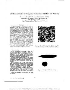
Animation on demand is a particular variant of automatic model driven animation. This approach is pictured in Figure 2. In animation on demand, the user requires the animation of a particular behavior supplying the animation goal identifying such behavior, while the entire animation sequence is automatically computed starting from the model, as described in Section 3.2. In Section 3 we have defined animation goals as predicates over the current and possibly the next state. They are derived from safety requirements or from conditions and events inside SCR tables. In animation on demand, the user can introduce new animation goals that can be complex temporal logic formulas expressing properties not
ANIMATOR
observe USER
SPEC
animation sequence
Animation Sequence GENERATOR
animation goal
Figure 2. Animation on demand
only on the current and next state but on a temporal sequence of events or conditions. We, therefore, extend the definition of animation goals allowing animation goals stated as CTL (Computational Tree Logic) or LTL (Linear Temporal Logic) formulas4 . As an example, consider the case in which the user wants to simulate the following scenario: system is not reset, then eventually the pressure of the water passes the Permit bound, then eventually it falls below Low, and then eventually the user blocks the safety injection. Formally, the animation goal is the sequence of the following four conditions and events: 1. 2. 3. 4.
Reset = Off @T(WaterPres > Permit) @T(WaterPres < Low) @(Block = On)
This sequence can be translated in CTL as: (2) Reset= Off & EF(WaterPres > Permit & EF(WaterPres < Low & EF(Block = On))) being EF the CTL operator eventually in the future5 . Once the user has written a particular animation goal, the model checker computes the animation sequence (if it exists) exploiting the use of the trap property (the negation of the animation goal) and the counter example generation. For example, SMV finds the counter example shown in Table 5 for the trap property of (2). The four conditions and events of the animation goal are written in bold. Animation on demand is based on human interaction with the animator; however, differently from the user driven approach, users do not have to build the complete sequence of inputs, but just describe the scenario by an abstract logical formula. The model checker generates the animation sequence that satisfies the animation goal and the user animates the sequence to check if the behavior is correct. The drawback of this 4 5
SMV is able to prove CTL formulas, while Spin uses LTL. The animation goal may contain other CTL temporal operators in order to state more complex formulas which are not necessary linear sequence of events and conditions.
state 1: initial state SafetyInjection = On Permit = 1000 Low = 900 Block = Off Reset = On WaterPres = 2 Pressure = TooLow Overridden = 0
state 3: WaterPres = 5 ... WaterPres increases ... state 95: Pressure Permitted SafetyInjection =Off WaterPres = 1001 Pressure = Permitted ... WaterPres decreases
state 2: SIS is reset Reset = Off
... state 96: Pressure TooLow SafetyInjection = On WaterPres = 998 Pressure = TooLow state 97: SIS is blocked Block = On Overridden = 1 SafetyInjection =Off
Table 5. Animation sequence for(2)
approach is that it requires some user skills in formulating a scenario as CTL or LTL formula. For this reason, the possibility of graphically building CTL or LTL formulas would be very useful (see Section 5).
4
An Animator Tool
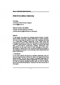
In this section, we describe the general architecture of a prototype tool we have realized for automatic graphical animation of SIS. The tool architecture is depicted in Figure 3.
Tests Generator Tool
Animator client
Animator service
Control Panel generated scenarios
select scenario
Animator (SIS) Panel
set var value
GUI level
show var change
Animator client Controller
Animator server Controller
Scenario Repository ORB
CONTROL level
COMMUNICATION level
Figure 3. Tool architecture
We distinguish three main components of the animator: 1. the Tests Generator Tool: following user requests, it generates scenarios exploiting the model checkers and stores them in a repository; it is described in [6,9] 2. the Animator client: it retrieves generated scenarios and drives the animator service by providing the scenario to animate (i.e. the values of variables);
3. the Animator service: it shows the system status and the system behavior by means of a graphical animator panel. Animator client and service have a three layers architecture. At communication level, client and server communicate through a CORBA ORB. At control level, the animator client controller and the animator server controller manage their graphical interfaces, start the processes, and connect and register themselves with the ORB. At GUI level, the animator client controls the animator through the control panel depicted in Figure 4. The control panel provides two different ways to animate a scenario: step by step (the user makes the animator progress by pressing the next state button) or automatically (the user selects the time interval between two consecutive states). The user selects scenarios to animate from a scenario repository. A graphical interface that helps the user to link table cells and property requirements to scenarios is under development.
Figure 4. Control Panel
The GUI part of the animator service is the real graphical panel that shows the system state and behavior. We have built the SIS panel using the standard Java graphical library by means of the graphical form editor provided by NetBeans6 . In Figure 5, we show the last two states for two animation goals: one for the property 1 at page 5 and one for the event table 3 at page 5. In the first case, WaterPres becomes less then Low, but the system is blocked and not reset, and, therefore, SafetyInjection stays Off. In the second case, the system has Pressure TooLow and is reset (Reset becomes equal to On), and, therefore, SafetyInjection becomes On. The architecture is highly modular and makes the animator easy to change. The animator panel can be easily substituted; this feature is relevant since each specification requires a new animator panel to be animated. Developing new animator panels is a matter of minutes using the form editor provided by NetBeans. Thanks to CORBA, the animator can work in a distributed way. The animator service may run on a remote machine, for example a computer of the customer, while the animator client would be controlled by the designer.
5
Related Work
There exist several tools and methods for animating formal specifications. [2] uses the B-Toolkit for animation of B specifications. The B-Toolkit presents the user a symbolic 6
www.netbeans.org
Animation of: @T(WaterPres