Automatic Online Walls Detection for Immediate Use in AR Tasks Gilles Simon∗ Nancy-Universit´e - INRIA Lorraine
A BSTRACT This paper proposes a method to automatically detect and reconstruct planar surfaces for immediate use in AR tasks. Traditional methods for plane detection are typically based on the comparison of transfer errors of a homography, which make them sensitive to the choice of a discrimination threshold. We propose a very different approach: the image is divided into a grid and rectangles that belong to the same planar surface are clustered around the local maxima of a hough transform. As a result, we simultaneously get clusters of coplanar rectangles and the image of their intersection line with a reference plane, which easily leads to their 3D position and orientation. Results are shown on both synthetic and real data. Keywords: plane detection, scene reconstruction, simultaneous localization and map-building, augmented reality 1
I NTRODUCTION
Scene acquisition is a prerequisite to a variety of AR task: 3D features are needed in camera tracking and to position the virtual objects with respect to the real world. Furthermore, 3D surfaces must be known to handle occulsions and collisions and/or ensure photometric consistency between the real and the virtual scenes. In most situations, scene geometry is obtained offline before the augmentation process starts. Nevertheless, some AR applications require the scene to be incrementally built while the user is discovering and augmenting the environment. For example, a collaborative mobile AR system was designed in [4] to improve the situation awareness and the coordination between groups of dismounted soldiers in urban battlefield. Names of buildings, routes, objectives and locations of other users were dynamically added to a shared augmented view of the environment. As the system was used for training, locations and models of the buildings were acquired beforehand. However, in real situations, these information must be recovered at the same time as other data. Many AR systems would also be of much simpler use if a preliminary scene acquisition step could be avoided. For instance, we show in section 4 an example of interior design application, where shadows of the added furniture are updated as new walls are detected. Incremental building of 3D maps for immediate use is a very challenging problem. Its difficulty primarily stems from the fact that it must be causal, i.e. rely only on past frames, and also permit a real time implementation. Recent advances in simultaneous localization and map building (SLAM) have been made in robot navigation reaserch [2]. However, in most of these approaches, scene reconstruction is not the final product but an intermediary stage that allows pose computation. As a result, models are generally poor, i.e. a set of sparse points, and cannot easily be used to position a virtual object or manage interactions between the real and the virtual scenes. In this paper, we present a causal, real time method to detect and incrementally reconstruct textured planar surfaces, like walls in urban or indoor environments. Or goal is not to ∗ e-mail:
[email protected]
recover a comprehensive description of the scene, but rather rough surfaces (actually sets of coplanar rectangles like in Fig. 4.(b)) that can be used to perform most of the above described AR tasks. The paper is organized as follows : section 2 describes our automatic planes detection algorithm and section 3 the 3D reconstruction procedure. Finally, results obtained on both synthetic and real data are presented in section 4. 2
P LANES DETECTION
Some algorithms have been proposed in the past to automatically detect planar regions (see for instance [5]). However, these methods are typically based on the comparison of transfer errors of a homography, which makes them very sensitive to the choice of a discrimination threshold. Moreover, they generally do not take into account the heteroscedastic nature of the transfer errors, leading to unequal results depending on the position and orientation of the planes with regard to the camera. For these reasons, we suggest a very different approach: our basic idea consists in dividing the image into a n × n grid, compute a dominant homography Hr per grid rectangle r and group rectangles that generate “similar” homographies. Yet, a crucial questions is how to decide that two homographies are similar. 2.1
Clustering method
Let’s first assume homographies Hr are computed between two images I0 and I1 , and describe the image transform of physical planes Πr . Let’s assume another homography Hre f is known, that describes the image transform between I0 and I1 of an arbitrary plane Πre f , non-parallel to planes Πr . Let lr be a 3-vector representing the projection in I0 of the intersection line Lr between planes Πr and Πre f (lr = (a, b, c)> where ax + by + c = 0 is the equation of the line in image plane). Theoretically, lr can be derived directly −> from Hr and Hre f as the real eigenvector of H> re f Hr . This is due to the fact that lr is transformed by H−> and H−> r re f into the same line, projection of Lr in image I1 [3]. Therefore, a basic procedure may consist in grouping grid rectangles that generate close projec−> is a non-symmetric tions of intersection lines. However, H> re f Hr matrix, which makes its eigenvectors extraction unstable. Moreover, this procedure would not take advantage of time consistancy in the image sequence. To solve these two problems simultaneously, we propose to discretize the line computation problem by randomly selecting K pixels pi in image I0 and keeping the k pixels for which values of Euclidean distance ||pi − H−1 re f Hr pi || are the smallest. A Hough transform is performed on these pixels, one Hough accumulator array Ar (ρ , θ ) been used per rectangle. Fixed lines are the locations (ρl , θl ) of the local maxima of a common accumulator array A(ρ , θ ) = ∑r Ar (ρ , θ ), and these lines are supposed common to any rectangle whose location (ρr , θr ) of the global maximum of Ar is at distance smaller than R from (ρl , θl ). By local maximum of A, we mean a value greater than a proportion P of the global maximum of A and greater than any other value of A in a circle of radius R. In our experiments, we took K = 3000, k = 3, P = 50% and R = 10 for a Hough resolution of 4 pixels and 0.5 degrees.
2.2
Time consistency
Let’s now assume the grid rectangles have been tracked over consecutive frames I0 , I1 , . . . , Ii and let Hir and Hire f denote the homographies that transform the planes Πr and (resp.) Πre f between images I0 and Ii (these homographies can be obtained by composing inter-image homographies). The same intersection line lr must −1 be obtained in image I0 when looking for fixed points of Hire f Hir , whatever value of i between 1 and i: this brings redundant information that enables us to take time consistency into account. In particular, rectangles are really grouped into a planar region if the location of the corresponding local maximum of A is persistent, that is detected in a sufficient number of consecutive frames (namely during a few seconds). This test precludes integrating rectangles whose tracking has drifted, or rectangles that do not correspond to physical planar surfaces (nor partially when homographies are computed robustly). The clustering procedure is illustrated in Fig. 1, that shows an example result we obtained on a real sequence of a miniature indoor scene (see section 4.2). The initial grid is shown in Fig. 1.(a). A 2D polygon corresponding to the reference plane Πre f (the ground of the room) was outlined by hand in the first frame of the sequence, and automatically tracked in the next images. Rectangles having more than one vertex inside that region were automatically discarded. Fig. 1.(b) shows the rectangles and the reference polygon obtained in frame 70. Keypoints correspondences between frame 69 and 70 are also represented in white. These were obtained using the RANSAC paradigm (see [6] for details). The Hough transform obtained in frame 70 is shown in Fig. 1.(c). Six local maxima were detected at the centers of the circles of radius R. Among them, only two maxima were tracked for a sufficient time to be integrated: these are the centers of the solid and dashed black circles. Lines corresponding to the six maxima are drawn in Fig. 1.(d), using the same line styles as for the related circles. Persistent maxima correspond to the intersection lines between the ground plane and the two visible walls. Clusters of six and three rectangles were obtained in that frame for the left and (resp.) right intersection lines (see Fig. 1.(d)). Note that in that example, two grids were used, one shifted from the other by half a rectangle: this permits to use large rectangles (that potentially provide more persistent maxima than smaller rectangles) while not losing too much in terms of reconstruction fineness.
2.3
(a)
(b)
(c)
Reference homography
In multiple wall environments, the ground plane constitutes a natural reference plane: reference homographies Hire f can then be obtained by tracking the corresponding region over the sequence, like in the above example. However, any virtual plane non-parallel to the planes Πr may be used, assuming the related homographies can be obtained. This is of particular interest when the ground is not planar, or when it is not visible in every frame of the sequence. In that case, and assuming the projection matrices are known, homographies Hire f can be obtained using equation Hire f = K(Ri − ti v> )K−1 , where (Ri |ti ) is the relative motion of the camera between image I0 and image Ii , K is the intrinsic matrix of the camera and v is the 3-vector (a/d, b/d, c/d)> , where ax + by + cz + d = 0 is the equation of the plane in the first camera coordinate system [3]. Note that d must be non-null, which precludes a plane Πre f passing through the center of the camera. A typical virtual plane that may be suitable in most situations is a horizontal plane passing through the feet of the user at the beginning of the process.
(d) Figure 1: Illustration of the clustering method (see explanations in the text).
2.4
Degenerate cases
A degenerate case arises when the camera undergoes a pure rotation, or when a grid rectangle is completely inside the reference > −> plane: in both cases, matrix Hire f Hir is theoretically equal to identity, and transforms any line into itself. Different methods such as model selection [6] may be used to detect this case and not increment the related accumulators when it occurs. However, we found it was not necessary to perform this task, due to the robustness of the Hough transform and the fact that time consistency is ensured. Another degenerate case is when the reference plane Πre f passes
2.5
Long time sequences
Until now, only the rectangles defined in image I0 could be added to a cluster and form a planar region. This greatly limits the applicability of the algorithm, as in real situations one generally expects to detect planes that were not visible in the first frame. However, to benefit from the principle of accumulation, intersection lines must be expressed in the same image. Therefore, every m images, the −> following steps are performed: i) homography Hire f is applied to the Hough accumulator arrays Ar (ρ , θ ) and A(ρ , θ ) (more exactly, to the lines represented by each position in the accumulator array, forming a new accumulator array) and to the locations of the local maxima (see left column of Fig. 3): this amounts to transfer the detected and potential intersection lines to the current frame Ii , ii) n × n rectangles are added in Ii using the same grid as in image I0 , iii) all homographies are reset to identity and new and old rectangles are tracked from the current frame. This permits to regularly introduce new rectangles that can generate new clusters or supplement clusters issued from old rectangles. Furthermore, as homographies are reset, this allows to prevent drift of local maxima in long time sequences. 3
R ESULTS
Results are shown on a synthetic and a real scene. Videos are joined to the paper that supplement the screenshots shown in this section. 4.1
10 8 6
Synthetic scene
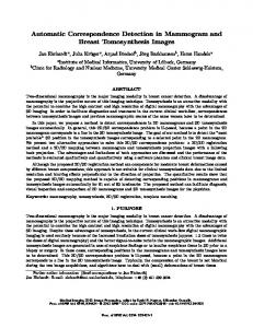
The synthetic scene consists of a camera moving through a corridor made of five walls and a floor (Fig. 2). 6 × 6 rectangles were introduced in the first frame of the 100 frames sequence (except inside the polygon that delimits the reference plane) and every 15 frames of the sequence. About 1000 points uniformly distributed in the images were used to track the rectangles and the reference polygon over the sequence, and a Gaussian noise of standard deviation
#4
4 2
E UCLIDEAN RECONSTRUCTION
The procedure we described in section 2 does not require the camera matrices to be known, except when the reference plane is not physically tracked over the sequence. However, when projection matrices and the equation of the reference plane are known, our method has the great advantage that it also provides 3D planes reconstruction as a by-product of the clustering algorithm. Indeed, given a projection matrix P and a line lr corresponding to a local maximum of A, there is a single 3D line Lr on Πre f that projects into lr . Lr is obtained by intersecting Πre f with the plane passing through lr and the center of the camera. Now, given the 3D line Lr , there is a one-parameter family of planes Π(θ ) that contain Lr (θ is for instance the angle between Πre f and Π(θ )). Alghough θ could be retrieved for any plane using the method presented in [1], we assume in this paper that Πr is perpendicular to the reference plane, which amounts to take Πr = Π(π /2). This assumption corresponds to a very common situation where the reference plane is a real or virtual horizontal plane and the detected planes are vertical walls. 4
σ was added to these points. Fig. 3 shows the accumulators array A(ρ , θ ), the local maxima and the corresponding clusters of rectangles obtained at frames 39, 55 and 73 with σ = 0.2. It is interesting to note that the part of plane #4 that was occluded by plane #1 in the first frame (see Fig. 2.(a),(b)) is well detected when it appears in the camera field of view, due to the periodic introduction of rectangles. Top of table 1 shows errors obtained on the reconstructed planes (error angle ∆θ on the normal to the plane and error ∆d on the distance to the origin) for σ =0., 0.1 and 0.2. Error angles are generally lower than 1 degree and error distances are small compared to the distance between planes #1 and #2 which is 2.26. Error distances are higher for plane #4 because this plane is detected soon in the sequence while still far from the camera (even if some rectangles added at the end of the sequence allow to refine a little bit the result). To assess the robustness of the system to errors on camera poses, we also added noise to these data. In order to introduce realistic noise, we computed the projection matrices using noisy correspondences on the reference plane and the camera tracking method presented in [6]. Bottom of table 1 shows the reconstruction errors obtained by adding a Gaussian noise of standard deviations 0., 0.1 and 0.2 on the matched points. The system is robust to these errors, except for plane #4 when σ = 0.2, for the same reason as previously (except that here the sequence is stopped at frame 60 because the reference polygon is not visible anymore after that frame).
y
through then center of the camera: then, any intersection line between Πre f and another plane Πr in the scene projects into the same line, intersection of Πre f with the image plane. Therefore, all the rectangles belonging to a plane are clustered into the same plane. However, this case never occurs when the reference plane is a physical one (unless the camera is moving on it) and must be avoided anyway when it is a virtual one, as mentioned previously.
(a)
0
#1 Camera path
-2
#2 -8
-6
-4
-2
#3
0
2 x
4
6
8
10
(b)
Figure 2: (a) Top view of the synthetic scene. (b) Rectangles introduced in the first frame of the sequence.
Plane #1 #2 #3 #4
Plane #1 #2 #3 #4
Exact camera poses σ = 0.0 σ = 0.1 ∆θ (deg) ∆d ∆θ (deg) ∆d 0.52 -0.02 0.82 -0.02 0.27 -0.01 0.28 0.05 0.60 0.01 0.26 0.05 0.80 0.09 0.85 0.21 Noisy camera poses σ = 0.0 σ = 0.1 ∆θ (deg) ∆d ∆θ (deg) ∆∆d 0.63 0.06 1.08 0.06 0.82 -0.02 1.16 0.01 0.25 0.04 0.71 0.12 0.79 0.07 0.28 0.08
σ = 0.2 ∆θ (deg) ∆d 1.15 0.01 0.97 0.02 1.30 -0.07 0.27 0.30 σ = 0.2 θ (deg) ∆d 1.13 0.05 0.31 -0.02 0.75 0.11 4.37 0.40
Table 1: Reconstruction errors obtained on the synthetic scene.
4.2
Real scene
We now present results obtained on a real miniature indoor scene. The reference plane z = 0 was outlined by hand in the first frame of the sequence (Fig. 1.(a)) and the projection matrix in that frame was obtained by indicating the four vertices of a rectangle [6] (Fig. 4.(a)). After this initialization step, the reference plane was automatically tracked using RANSAC on keypoints correspondences, which enabled us to sequentially update the camera matrix as detailed in [6] and at the same time obtain the reference homographies. New rectangles were introduced in the first frame (Fig.
(a)
(b)
(c)
(d)
Figure 4: Results obtained in the real sequence. (a) The initial camera matrix is obtained by pointing out four vertices of a rectangle. (b) Reconstructed clusters of rectangles at frame 164. (c),(d) Some augmentation results obtained in frame 1 and 70.
5
Figure 3: Hough transform, local maxima and the corresponding clusters of rectangles at frames 39,55 and 73 of the synthetic sequence.
1.(a)) and every 100 frames of the sequence. Two local maxima were detected at frame 70 of the sequence (Fig. 1.(c),(d)) and the related clusters of rectangles were supplemented until frame 164, were clusters of 10 and 7 rectangles were obtained for the left and (resp.) right wall. Fig. 4.(b) shows the reconstructed reference plane and clusters of rectangles obtained at frame 164 (textures are taken in the images where the rectangles are introduced). As the calibration rectangle was put at the corner of the room, the expected equations of the walls are x = 0 and y = 0. Normals to the reconstructed planes have 1.2 deg angular errors for the left wall and 1.5 deg for the right wall, and distances to the origin have 0.7 mm error for the left wall and 9.2 mm for the right wall. These errors can be visually assessed in Fig. 1.(d) by looking at the difference between the displayed lines and the real bases of the planes: these are widely acceptable for most of AR tasks like collision detection or shadow casting. Note that, depending on the application, the clusters of rectangles can be extended down to the intersection with the reference plane and/or cut at intersections with the reference plane and other clusters of rectangles. In some applications, equations of the planes are only needed. By instance, shadows of the virtual chair in Fig. 4.(c),(d) were obtained using the recovered equations of the planes. In Fig. 4.(c), the ground plane only was known and the shadows are non consistent. These become consistent in frame 70 as walls are detected (Fig. 4.(d)).
C ONCLUSION
In this paper, we have presented a novel approach for automatically detecting planar surfaces and getting their 3D position and orientation as a by-product. By formulating the problem into a local maxima search in a Hough transform, we benefit from the robustness of the Hough transform as well as from the fastness and time consistency brought by the principle of accumulation. We now plan to test if the accuracy provided by outdoor sensors (e.g. an inertial sensor and a GPS) is sufficient to detect walls (even roughly) in a urban environment. A hybrid SLAM algorithm may then be envisaged, where the detected walls would be used at their turn to refine the pose provided by the sensors. R EFERENCES [1] C. Baillard and A. Zisserman. Automatic reconstruction of piecewise planar models from multiple views. In Proc. IEEE Conference on Computer Vision and Pattern Recognition, pages 559–565, June 1999. [2] Andrew J. Davison and David W. Murray. Simultaneous localization and map-building using active vision. IEEE Transactions on PAMI, 24:865–880, 2002. [3] R. I. Hartley and A. Zisserman. Multiple View Geometry in Computer Vision. Cambridge University Press, ISBN: 0521623049, 2000. [4] ”S. Julier, Y. Baillot, M. Lanzagorta, D. Brown, and Rosenblum”. Bars: Battlefield augmented reality system. In NATO Symposium on Information Processing Techniques for Military Systems, Istanbul, Turkey., pages 9–11, October 2000. [5] M. Lourakis, A. Argyros, and S. Orphanoudakis. Detecting planes in an uncalibrated image pair. In In Proc. of BMVC’02, volume 2, pages 587–596, 2002. [6] Flavio Vigueras, Marie-Odile Berger, and Gilles Simon. Iterative multi-planar camera calibration: Improving stability using model selection. In Eurographics Association, editor, Vision, Video and Graphics (VVG)’03, Bath, UK, Jul 2003.