Automatic SAR Image Registration by Using Element Triangle Invariants Xin Kang School of Electronic & Information Engineering, Xi’an Jiaotong University, China Xi’an 710049, P. R. China. Email:
[email protected]
Chongzhao Han School of Electronic & Information Engineering, Xi’an Jiaotong University, China Xi’an 710049, P. R. China. Email:
[email protected]
Abstract - Due to the presence of speckle in synthetic aperture radar (SAR) image, the existing registration algorithms, which are successfully used in optical remote sensing image, are usually not applicable to it directly. An automatic SAR image registration algorithm is proposed in this paper. Firstly, the element triangles are constructed from the point targets detected from the SAR images; then they are matched by integrating triangle moment invariance proposed in this paper and region invariant moments; finally, the LMSE algorithm is used to estimate the affine transformation parameters, thus the SAR images can be registered automatically. The proposed algorithm is evaluated and compared with the existing methods by means of invariant moments (IM) and affine moment invariants (AMI). It is shown from Monte-Carlo simulations that the proposed algorithm is robust to detection error and partial correspondence of control points (CPs), and has higher ratio of correct matching than the methods using IM or AMI. Experimental results show that the proposed new algorithm is not only valid in the automatic registration of SAR images, but also can avoid the influence caused by speckle in feature detection and feature matching process. Keywords: Image registration, feature detection, feature matching, image fusion.
1 Introduction Image registration as a fundamental task in image processing is used to geometrically align two or more images of the same scene at different times, from different viewpoints, and/or from different sensors. It is a crucial step in all image analysis tasks in which the final information is gained from the combination of various data sources, like in image fusion, change detection, multi-channel image restoration, and etc. Existing image registration techniques broadly fall into two categories: the area-based and the feature-based methods[1]. In the area-based methods, the matching measure is usually the normalized cross-correlation. These methods are not welladapted to the SAR and/or multi-sensor image registration. Feature-based registration methods, which extract and match the common structures from two
Yi Yang School of Electronic & Information Engineering, Xi’an Jiaotong University, China Xi’an 710049, P. R. China. Email:
[email protected]
images, have been shown to be more suitable for this task[2, 3]. Because of the presence of speckle in SAR image, algorithms and approaches successfully used in optical remote sensing image are frustrated. Contours are the general structure feature in images. But, the presence of speckle noise due to the coherent nature of the illumination makes it difficult to detect good edge and contour in SAR image[4, 5]. Various smoothing techniques can be applied before edge detection, but this in turn may affect the accuracy of the contour location. Good results based on the Canny edge detector were reported in [6] and [7]. However, many contours corresponding to continuous boundaries were broken. The LoG edge detector can produce unbroken contours, but also generates false contours because of the textural patterns present in the SAR image. For SAR image registration, the basic contour matching methods do well in optical image registration are thwarted. This paper proposes a novel algorithm for SAR image registration. Instead of detecting and using contours in image, the algorithm uses triangle as the basic element for registration. The triangle is called element triangle in this paper. Taking strong scatterers in SAR image as its vertices, the element triangles are a set of triangles built by connecting each point to its natural neighbors. Hence, the problems in edge/contour detection, edge linking, and false contour removing are avoided. At the same time, the image is split into several regions, which is called element regions, by element triangles, and the normal regionbased feature can be used in matching process. Furthermore, a new affine invariant is proposed and used to match element triangle. By combining these two similarity measures, the affine transformation parameters can be estimated. In Sec. 4, three types of Monte-Carlo simulations corresponding to real situations are performed. Comparing with methods using IM and AMI, the robustness of the proposed method is demonstrated at the same time. An experiment for applying the algorithm to real RADARSAT SAR image registration is also given in this section. Finally, concluding remarks are provided in Sec. 5.
2 Registration Feature and Measures
2.1 Control point extraction Point feature is a general feature in image registration, and a large group of registration methods use this feature as control points (CP). There are many types of point feature which can be used as CP, such as centroid or center of a region, the center of gravity of the closed boundaries, region corners, line intersections, line ends and points on curves with high curvature, and etc. Although all these feature points can be used in our method, the corner or point feature detectors are chosen in order to avoiding the problem caused by speckle. Due to the poor performance of the well-known corner detector such as Harris[8] and SUSAN[9] corner detector in SAR image, strong scatterers[4] are adopted as the feature points in this paper. Strong scatterers (as feature points) detection can easily be done by using point target detector proposed in [4]. The detector, which is based on the ratio of the mean value of an inner window to that of the outer window, was shown to be efficient for point target detection[4, 10]. Since the point target signal does not satisfy the multiplicative speckle model, the ratio of the inner and outer window is beyond a statistically determined threshold. And the threshold can be determined by fixing a constant false alarm rate. It is an important problem that the much closer the matched CPs are, the less accuracy the estimated transformation parameters are. To deal with this problem, an user-defined radius is used to spread out the detected CPs. Also, this post-processing could make the element triangle big enough to build triangle invariants as described in next section.
2.2 Triangle invariants There exist two kinds of invariants: relative invariants and absolute invariants. Mathematically, a relative invariant is represented as[11] I R ( p, a ) = Δ ⋅ I R ( p, a ) (1) where p ∈ R 2 , Δ depends only on the transformation parameters. An absolute invariant can easily be obtained by eliminating Δ between two relative invariants. Assuming that reference image and sensed image have m and n points, respectively, and they have k points in common. Let P = { p1 , p2 , , pm } be a set of points in reference image and Pa = { pa ,1 , pa ,2 , , pa , n } be a set of
points in sensed image. By selecting three points from P and Pa , there are r ≤ Cm3 and q ≤ Cn3 element triangles. Denoting these element triangles as T = {t1 , t2 , , tr } and Ta = {ta ,1 , ta ,2 , , ta , q } , respectively. The ith element triangle, which is arbitrarily picked up from reference image, is split by its centroid ( xix , yic ) into three subtriangles. The area of each sub-triangle is det{S k (i )} 2,
xi
yi
1
S1 (i ) = xic
yic
1 , S 2 (i ) = xic
xi +1
yi +1 1
xi + 2
yi + 2 1
S3 (i ) = xic xi
yic yi
xi +1 xi + 2
yi +1 1 yic
1,
yi + 2 1
(2)
1. 1
Assuming the jth element triangle in Ta is an affine mapping image of the ith element triangle in T . Correspondingly, the area of each sub-triangle is det{Sa , k (i )} 2, (k = 1, 2,3) , whose formulation is similar to eq. (2). These areas are relative affine invariants. Absolute invariants can be derived by considering the ratio of any pair of triangles. Ideally S (i ) S ( j ) I kl (i ) = k = a , k = I a , kl ( j ) Sl (i ) S a ,l ( j ) (k , l = 1, 2,3. and k < l ) (3) Remark: If three points are collinear, the ratio of the length of any two points can be used as affine invariants, instead.
2.3 Affine moment invariants Moment invariants are useful features of a twodimensional image as they are invariant to translation, to changes of scale and to rotations of the image. Affine moment invariants[12-15] are useful features in pattern recognition as they are invariant to arbitrary general linear transformations of the image. The lower-order invariants, which are composed of the second-order and third-order central moments, are usually sufficient for most registration tasks on remotely sensed image matching.
3 Combined Image Registration 3.1 Element triangle matching error matrix For each element triangle, there is an affine invariant feature associated with it. Let I (i ) = {I kl (i ) | i = 1, 2, , r} and I a ( j ) = {I a , kl ( j ) | j = 1, 2, , q} denote the values of three area ratio invariants of the element triangles in the reference image and the sensed image. To find out the feature points in the reference image that appear as feature points on the sensed image, following matching error measure is used e(i, j ) = I (i ) − I a ( j )
2
(4)
The result is an r × q matrix in 3 dimension feature space, in which each element represents a reliable similarity measure between the element triangle in two images.
(k = 1, 2,3) , where
3.2 Invariant-moments distance matrix
Let φ k (i ) (k = 1, 2, , 7; i = 1, 2, , r ) and φak ( j ) (k = 1, 2, , 7; j = 1, 2, , q ) denote the values of the seven invariant moments of the element regions built in the reference image and in the sensed image, respectively. For each region in the reference image and sensed image, we compute the invariant-moment distance between element regions i and j d (i, j ) =
7
∑ [φ k =1
k
(i ) − φak ( j )]2
(5)
The result is also an r × q distance matrix in 7 dimension feature space, which represents the similarity between the element regions in two images. Based on the principle of minimum distance classifier, the distance is the similarity measure of the two regions.
3.3 Candidate merging Methods such as in [16] use the top three matched counterpoints for parameter estimation. But, are the top three matched counterpoints real corresponding points? Do the CPs obtained from the top three matched pairs spread out widely enough in the image space? The answers for all these questions are uncertain. In our algorithm, if only the vertices of the most three matched element triangles are used in the affine transformation parameters estimating process, there are at least 5 pairs and at most 9 pairs of CPs. Obviously, the more correctly corresponded CPs are taken and more widely the CPs spread out in the image, the more accuracy the estimated parameters are. So, an additional procedure called candidate merging is introduced in order to verify and extract correct corresponding CPs. Eliminating the element triangles used to estimate parameters from ψ , the remained candidates construct a new set Λ . According to the transformation parameters estimated, calculating the following equation for each pair of candidate matched CP Ei = ( xi′ − xi ) 2 + ( yi′ − yi ) 2 (6) which
( xi′, yi′) = ( xa , j , ya , j ) ⋅ A + b
(7)
In fact, Ei is the RMS error of the ith candidate matched CP by means of the estimated parameters. So, given the maximum RMS error Er , if Ei < Er the candidate CP pair is kept in Λ ; otherwise, it is deleted from Λ . In the end, the CP pairs used to estimate affine transform parameters are put back into Λ . All these CPs are used to estimate the final affine transformation parameters.
3.4 The algorithm of image registration Based on the two similarity matrices defined above, the following registration algorithm is developed. 1) Based on the output of the feature points detection and sorting program, the m points in the reference image and the n points in the sensed image are filtered (the feature points close to image margin are not credible) and shrunk (the feature points too close to each other provide too small element triangle useless).
2) Using the reduced points, the r element triangles in the reference image and the q element triangles in the sensed image are built, labeled, and ordered. Let T = {t1 , t2 , , tr } and Ta = {ta ,1 , ta ,2 , , ta , q } denote these element triangles, and let ψ denotes a set of the potential matched element triangles. Here, the Delaunay triangulation is used to build element triangles. 3) Compute two r × q feature matrices, D = {d (i, j )} and E = {e(i, j )} , for each element triangle. 4) Working with the potential matching set ψ , the minimum distance classification is performed based on min( Di , j ⋅ Ei , j ) |(i , j )∈ψ (8) and the three pairs of regions with minimum values are identified as the matched element triangles. 5) Perform candidate merging as described before. 6) Based on the matched pairs of element triangles, there have N (N>3) matched CPs. Then, the affine transformation parameters can be solved by minimizing the LMSE estimation N
∑ i =1
pa ,i − ( A ⋅ pi + b)
(9)
The outputs from the step 6 are six parameters of the affine transformation between the reference image and the sensed image. Remark: There can be an additional step in the algorithm between step 3 and step 4. For any pair of element triangles ∀(i, j ) , if D(i, j ) < Td and E (i, j ) < Te , the pair is left in ψ , where Td and Te are userdefined thresholds. However, the two thresholds may change in different SAR image scenes.
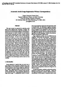
4 Evaluation and Experiment 4.1 Evaluation and comparison In this section, several types Monte-Carlo simulations are performed to evaluate the proposed method and to compare it with IM- or AMI-based methods. A SAR image and an IKONOS image are used. For SAR image, the candidate CPs are obtained by extracting strong scatterer targets; and for IKONOS image, the candidates are randomly generated. The CPs’ coordinates are recorded as the true position for evaluation and comparison. The candidate CPs and their triangulation in the original images are shown in Fig. 1(a) and Fig. 2(a). Considering the real situation, the following aspects are evaluated and compared with the methods using IM or AMI. Firstly, the robustness to the position detection error is considered. Assuming the detection errors in direction x and y are independent and both obey uniform distribution U (1, N ), N ∈ R + . Hence the maximum position detection error is 2 N . Detection errors are generated randomly in direction x and y separately and added on the true coordinates. Then 100 Monte-Carlo simulations are performed. In each Monte-Carlo simulation, the accuracy of using IM and AMI are also calculated for comparison.
It is necessary to note that the higher the order of AMI is, the more sensitive it is to noise[16], so the first to fourth order of AMIs are used in this paper. In order to avoid influence of additional process such as geometric transformation or interpolation, the original images are not affine transformed. Let N = 5 , the positions before and after adding detection errors of one simulation are plotted in Fig. 1(b) and Fig. 2(b). Comparing with IM and AMI methods, the average accuracy of each method is calculated after 100 simulations as shown in Table 1. Table 1 Monte-Carlo simulation and comparison of position detection error IM AMI Proposed method RADARSAT 82.58% 72.36% 90.82% IKONOS 74.59% 72.77% 98.95% Secondly, the robustness to the partial correspondence of the CPs is considered. The case is simulated by eliminating one or two CPs from the candidate set randomly. The position errors are also added for the remained CPs with N = 5 . For the reason mentioned before, no geometric transformation and interpolation are made. Fig. 1(c) and Fig. 2(c) show one Monte-Carlo simulation situation of eliminating 12# CP in SAR image and 15# and 16# CPs in IKONOS image, respectively. Together with IM and AMI methods, the comparison results of the average accuracy of 100 Monte-Carlo simulations are listed in Table 2.
(a)
(b)
Table 2 Monte-Carlo simulation and comparison of partial correspondence IM AMI Proposed method RADARSAT
48.35%
40.93%
59.34%
IKONOS
67.95%
65.19%
89.90%
For the comprehensive case, position error, partial correspondence and affine transformation are all combined together. The two images are affine transformed using eq. (10) and added position detection error with N = 5 and 12# CP in SAR image and 16# CP in IKONOS image are removed, separately, and the interpolation method is bicubic. One of 100 Monte-Carlo simulations is shown in Fig. 1(d) and Fig. 2(d). Table 3. gives the average accuracy of the three methods. ⎡ cos(π 36) sin(π 36) ⎤ ⎡10⎤ (10) A = 0.8* ⎢ , b=⎢ ⎥ ⎥ ⎣ − sin(π 36) cos(π 36) ⎦ ⎣3⎦
(c)
Table 3 Monte-Carlo simulation and comparison of the comprehensive case IM AMI Proposed method RADARSAT 82.58% 72.36% 90.82% IKONOS 35.14% 38.10% 75.71% (d) Fig. 1 : Experiment of SAR image. Original image (a) is added position detection error with N=5 (b), added position detection error with N=5 and removed 12# GCP (c) and in the comprehensive case (d).
(a)
(b)
(c) (d) Fig. 2 : Experiment of IKONOS image. Original image (a) is added position detection error with N=5 (b), added position detection error with N=5 and removed 15# and 16# GCPs (c) and the comprehensive case (d). Furthermore, several approaches, such as [17], [18] and [19], have been proposed in order to obtain sub-pixel accuracy in the image interpolation step. These approaches can be adopted as a post processing, but are not used in this paper for their computational expensiveness. From the Monte-Carlo simulations, it can be seen that the accuracy of the proposed method is higher than the method using IM and AMI in all these three cases. The robustness partly owes to avoiding edge/contour detection, edge linking, and false contour removing in such multiplicative noise situation as in SAR image or complex texture case as in IKONOS image, partly attributes to the candidate merging procedure. As the IKONOS image in comprehensive case an example, the percentage of correct matched CPs is 75.71% and the top three matched element triangles are Δ(4, 6, 9) ∼ Δ (3, 6, 9) , Δ (3, 4, 6) ∼ Δ(3, 4, 9) and Δ (4, 5, 9) ∼ Δ (1, 3, 6) . Hence, five pairs of CPs are used to estimate the parameters without candidate merging and other pairs
GCP
are only used for calculating error. The RMSE for each CP after registration is err1 listed in Table 4. The average RMSE is 0.85 pixel. By using candidate merging step, all the 15 pairs are correctly matched. The RMSE of each CP after registration is calculated and listed in Table 4 as err2, and the average RMSE is 0.31 pixel. It is not only a step to verify and extract correctly matched CP pairs, but also make much more and widely distributed CP pairs to take part in the parameters estimation. Thus, it can be said that candidate merging process improves the accuracy and robustness to a certain extent.
4.2 Application to SAR image The experimental result using the proposed algorithm for automated RADASAT SAR image registration is provided as shown in Fig. 3. Fig. 3(a) and (b) show two SAR images taken from the same sense with slight affine transformation. Thirteen feature points and nine feature
Table 4 The RMSE of the GCPs after registration (in pixel) 1 2 3 4 5 6 7
8
err1 err2
0.02 0.34
0.13 0.31
0.13 0.17
0.04 0.22
0.05 0.40
1.10 0.26
1.51 0.39
1.41 0.15
GCP
9
10
11
12
13
14
15
avg.
err1 err2
1.50 0.54
0.83 0.17
1.36 0.32
1.45 0.34
1.47 0.47
0.33 0.47
1.04 0.11
0.85 0.31
points are detected in two images. The element triangles built by feature points in two images are respectively shown in Fig. 3(a) and (b) too. We do not use all the possible combination of the feature points to build element triangles, just use the nature neighbors. Finally, the transformation parameters are estimated. ⎧ x′=0.9975 ⋅ x - 0.0525 ⋅ y + 25.2687 (11) ⎨ ⎩ y ′=0.0520 ⋅ x + 0.9977 ⋅ y - 0.6210 The registration result is shown in Fig. 3(e).
SAR image, which avoid the contour detection process that is frustrated in SAR image. Then, the registration has been done by integrating the two type invariants of the element triangle and region. Both Monte-Carlo simulations and experiment show that the proposed algorithm can perform well. A possible future research topic is to use the multisensor images in our experiments. Otherwise, the much closer the matched CPs are, the less accuracy the estimated transformation parameters are. And the more of the correct matching pairs are, the more accuracy the estimated transformation parameters are. Hence, another future research topic is to develop a selecting decision method, which can make the number of matched points be as much as possible and the distribution of them in image space be as uniform as possible.
Acknowledgements
(a)
This work is partly supported by Key Fundamental Research (973) Program of China, No. 2001CB309403, and partly supported by National Natural Science Foundation of China, No.60574033.
References
(b)
(c) Fig. 3 : The element triangles of the reference image (a) and sensed image (b); and the registration result (c).
5 Conclusions In this paper, an algorithm for automatic SAR image registration using the features of virtual element triangles and regions is presented. Feature points and the geometric relationship between them give us a lot of structure information of the image. The proposed method is a novel idea to build triangles from feature points detected in
[1] B. Zitová and J. Flusser, Image registration methods: a survey, Image and Vision Computing, 21(11):977-1000, Oct. 2003. [2] F. Eugenio, F. Marqués, and J. Marcello, A contourbased approach to automatic and accurate registration of multitemporal and multisensor satellite imagery, IGRSS 2002, 6:3390-3392, June 2002. [3] Yao Jianchao, Image registration based on both feature and intensity matching, IASSP 2001, 3:16931696, May 2001. [4] R. Touzi, A. Lopes, and P. Bousquet, A statistical and geometrical edge detector for SAR images, IEEE Trans. Geosci. Remote Sensing, 26(6):764-773, Nov. 1988. [5] A. C. Bovik, On detecting edges in speckle imagery, IEEE Trans. Acoust., Speech, Signal Processing, 36(10):1618-1627, Oct. 1988. [6] M. Ali and D. Clausi, Using the Canny edge detector for feature extraction and enhancement of remote sensing images, IEEE IGRSS 2001, vol. 5, pp. 2298-2300, July 2001. [7] E. Rignot, et al., Automated multisensor registration: requirments and techniques, Photogrammetric Eng., Remote Sensing, 57(8):1029-1038, Aug. 1991. [8] C. Harris and M. Stephens, A combined corner and edge detector, Proc. Alvey Vision Conf., 147-151, 1988. [9] S.M. Smith and J.M. Brady, SUSAN - a new approach to low level image processing, Int. Journal of Computer Vision, 23(1):45-78, May 1997. [10] M. Walessa and M. Detcu, Model-based despeckling and information extraction from SAR image, IEEE Trans. Geosci. Remote Sensing, 38(5):2258-2269, Sept. 2000. [11] Z. Yang and F. S. Cohen, Image Registration and Object Recognition Using Affine Invariants and Convex Hulls, IEEE Trans. Image Processing, 8(7):934-946, July 1999.
[12] T. H. Reiss, The revised fundamental theorem of moment invariants, IEEE Trans. Pattern Anal. Machine Intell., 13(8):830-834, 1991 [13] J. Flusser and T. Suk, Pattern recognition by affine moment invariants, Pattern Recognition, 26(1):167-174, Jan. 1993. [14] J. Flusser and T. Suk, Affine moment invariants: A new tool for character recognition, Pattern Recognition Letters, 15(4):433-436, April 1994. [15] S. K. Bose, K. K. Biswas and S. K. Gupta, Model based object recognition-the role of affine invariants, Artificial Intelligence in Engineering, 10(3):227-234, Aug. 1996. [16] J. Flusser and T. Suk, A moment based approach to registration of images with affine geometric distortion, IEEE Trans. Geosci. Remote Sensing, 32(2):382-387, March 1994. [17] Y. Bentoutou, N. Taleb, M. Chikr, El Mezouar, M. Taleb, and L. Jetto, An invariant approach for image registration in digital subtraction angiography, Pattern Recognit., 35(12):2853–2865, Dec. 2002. [18] L. Van Tran and J. Sklansky, Flexible mask subtraction for digital angiography, IEEE Trans. Med. Imag., 11(3):407–415, Sep. 1992. [19] G. S. Cox and G. de Jager, Automatic registration of temporal image pairs for digital subtraction angiography in medical imaging, in Proc. SPIE Image Processing, 2167:188–199, Feb.1994.