8th International Conference on DEVELOPMENT AND APPLICATION SYSTEMS S u c e a v a, R o m a n i a, M a y 25 – 27, 2 0 0 6
AUTOMATIC TUNING OF PID CONTROLLER USING FUZZY LOGIC Gaddam MALLESHAM, Akula RAJANI Department of Electrical Engineering University College of Engineering (A) Osmania University, Hyderabad, A.P. -500007, India Email:
[email protected] Website: www.eee-ouce.org;www.ouce.com Phone Num: 9346643661 (Mobile):040-27098628 (Office) Abstract In this paper the new methodology for designing of PID controller is presented. PID controllers are the most widely used controllers in the industry. Although much architecture exists for control systems, the PID controller is mature and well-understood by practitioners. For these reasons, it is often the first choice for new controller design. There are many methods proposed for the tuning of PID controllers out of which Ziegler Nichols method is the most effective conventional method. In this paper, optimum response of the system is obtained by using fuzzy logic controllers. The method used here is fuzzy set point weighting. A comparison of the performance of fuzzy set point weighted controller is performed not only with the conventional methods of tuning but also with different shapes and numbers of designed membership functions. Keywords: PID (proportional-integral-derivative), Fuzzy Logic (FL), Ziegler Nichols Method (ZN), Fuzzy Set Point Weighting Controller (FSPWC), Membership Functions (MF)
a) Careful consideration was not given to the units of gains and other parameters. b) The process dynamics were not wellunderstood when the gains were first set, or the dynamics have (for any reason) changed. c) Some characteristics of the control system are direction-dependent (e.g. actuator piston area, heat-up/cool-down of powerful heaters). d) You (as designer or operator) think the controllers can perform better. Always remember to check the hardware first because there are many conditions under which the PID may not have to be tuned. These conditions are when 1) A control valve sticks. Valves must be able to respond to commands. 2) A control valve is stripped out from highpressure flow where the valve’s response to a command must have some effect on the system. 3) Measurement taps are plugged, or sensors are disconnected. Bad measurements may have you correcting for errors that don’t exist. Once fix these hardware problems then depending on the responses we obtain an appropriate decision can be taken whether or not to tune a PID controller. [2]
1. Introduction Tuning of PID controllers has always been an area of active interest in the process control industry. Ziegler Nichols Method (ZN) is one of the best conventional methods of tuning available now [1]. Though ZN tunes systems very optimally, a better performance is needed for very fine response and this is obtained by using Fuzzy Logic (FL) methodology which is highly effective. The FL methodology used in this paper is applied in the form of Fuzzy Set Point Weighting Controller (FSPWC) [1,7]. The idea of multiplying the setpoint value for the proportional action by a constant parameter less than one is effective in reducing the overshoot but has the drawback of increasing the rise time. To achieve both the aims of reducing the overshoot and decreasing the rise time, a fuzzy module can be used to modify the weight depending on the current output error and its time derivative [7]. Thus by using FSPWC, which was suggested by Antonio Visioli and modifying it in accordance to our desired performance criteria, simulation of the FSPWC is performed in MATLAB to obtain desired results.
2.Tuning And Its Purpose A PID may have to be tuned When 120
(
2.1 Trial and error method
)
K 1 + sTI + s 2TI TD GC ( s ) = (2) sTI The characteristic equation of the closed loop system becomes ⎛ 1 1 K KT ⎞ ⎛ 1 K K⎞ K K (3) s3 +s2⎜⎜ + + P D ⎟⎟+s⎜⎜ + P ⎟⎟+ P =0 ⎝T1 T2 T1T2 ⎠ ⎝T1T2 T1T2 ⎠ TIT1T2 A suitable closed-loop characteristic equation of a third-order system is (s + αω ) s 2 + 2ζωs + ω 2 = 0 (4) Which contains two dominant poles with relative damping ( ζ ) and frequency (ω), and a real pole at –αω. Identifying the coefficients in these two characteristic equations determines the PID parameters K, TI and TD. The solution is T T ω 2 (1 + 2ζα ) − 1 K= 1 2 (5) KP
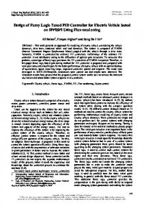
This process is a very time consuming process as a lot of permutations and combinations are involved. Though many iterations are performed the final result is not satisfactory. A balance is not obtained between the rise time and % overshoot even though a lot of possible combinations of the gains are incorporated. Continuous cycling may be objectionable because the process is pushed to the stability limit. Consequently, if external disturbances or a change in the process occurs during controller tuning, it results in unstable operation. The tuning process is not applicable to processes that are open loop unstable because such processes typically are unstable at high and low values of Kc but are stable at an intermediate range of values. It can be observed in Figure 1 that large overshoot is obtained as the program is written for faster rise time hence compromising with overshoot. All the time response specifications cannot be balanced using trial and error method.
(
)
T1T2ω 2 (1 + 2ζα ) − 1 T1T2αω 3 T T ω (α + 2ζ ) − T1 − T2 TD = 1 2 T1T2ω 2 (1 + 2ζα ) − 1 TI =
(6) (7)
Figure 1 Unit step response of the system G1(s) tuned with trial and error method.
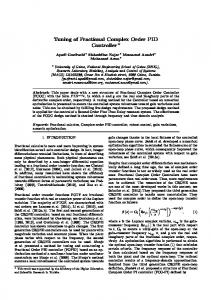
2.2 Pole placement method
Figure 2 Response of a system tuned with Pole Placement Method.
If the process is described by a low-order transfer function, a complete pole placement design can be performed. Consider for example the process described by the second-order model.
G (s ) =
KP (1 + sT1 )(1 + sT2 )
2.3 Ziegler nichols method t ⎡ ⎤ de(t) 1 u(t) = Kp ⎢e(t) +Td + ∫ e(τ )dτ ⎥ dt Ti 0 ⎣ ⎦
(1)
(8)
Ziegler Nichols formula ensures good load disturbance attenuation, but it generally provides a poor phase margin and therefore it produces a large overshoot and settling time in the stepresponse. The overall control scheme for Ziegler Nichols Method is shown in Figure 3.
This model has three parameters. By using a PID controller, which also has three parameters, it is possible to arbitrarily place the three poles of the closed loop system. The transfer function of the PID controller in parallel form can be written as 121
Figure 3. Control Scheme for Ziegler Nichols Method. Figure 7. Response for system G1(s) tuned with fixed ‘b’ method.
Figure 4. Unit step response of the system G1(s) tuned with ZL method. Figure 8. Response for system G2(s) tuned with fixed ‘b’ method.
3. Fuzzy set-point weighting: 3.1 PID tuning with fuzzy set-point weighting The PID controller has the following well-known standard form in the time domain
Figure 5. Unit step response of the system G2(s)tuned with ZL method.
t ⎡ ⎤ de(t) 1 u(t) = K p ⎢e(t) + Td + ∫ e(τ )dτ ⎥ dt Ti 0 ⎣ ⎦
2.4 Ziegler nichols with fixed set-point weighting ‘b’
The typical tuning problem consists of selecting the values of these three parameters, and many different methods have been proposed in the literature in order to meet different control specifications such as set-point following, load disturbance attenuation, robustness with respect to model uncertainties and rejection of measurement noise. Using the Ziegler-Nichols formula generally results in good load disturbance attenuation but also in a large overshoot and settling time for a step response that might not be acceptable for a number of processes. Increasing the analog gain K generally highlights these two aspects. An effective way to cope with this problem is to weight the set-point for the proportional action by means of a constant b