to be changed rapidly and easily thus reducing design time and eliminating human ... is used to send start and stop commands remotely to the vehicles. It consists of a ... the main propulsion unit and as many vehicle systems as necessary (e.g. ... a complete stop. ... the mission planner takes the RNDF and the MDF and finds.
Automatically Synthesizing a Planning and Control Subsystem for the DARPA Urban Challenge Hadas Kress-Gazit,George J. Pappas* GRASP Laboratory, University of Pennsylvania Philadelphia, PA 19104, USA {hadaskg,pappasg}@grasp.upenn.edu Abstract— To incorporate robots into society, they must be able to perform complex tasks while interacting with the world around them in a safe and dependable manner. The recent DARPA 2007 Urban Challenge made a step towards that goal by testing how well robotic vehicles can interact in an urban environment while dealing with static and dynamic obstacles and other cars. This paper uses the Urban challenge to demonstrates a general approach for automatically synthesizing correct hybrid controllers from high level descriptions. Here we create a planning and control subsystem for the vehicle that, if the information gathered by the sensor is correct, satisfies the requirements of the challenge for different dynamic environments. This approach automatically produces a system that is guaranteed to behave according to the traffic laws while interacting with other vehicles. Furthermore, it allows systems to be changed rapidly and easily thus reducing design time and eliminating human error.
Qualification Event (NQE).
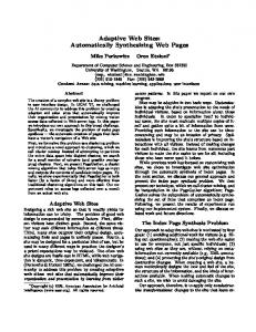
I. I NTRODUCTION Robots are different from other hardware and software systems in that they are expected to perform different complex tasks in dynamically changing and partially known environments, while ensuring the safety of their surroundings and themselves. To achieve this goal, robots must employ advanced control methods together with sensing capabilities and the ability to reason and make decisions about their state and the state of the world surrounding them. One of the major challenges for designing such systems [1] therefore is to find methods for combining these different requirements in a unified, effective and verifiable way. The Defense Advanced Research Projects Agency (DARPA) 2007 Urban Challenge is the second of two challenges initiated by DARPA that put to the test the ability of current technology to deal with these challenges. Its predecessor, the 2005 Grand Challenge required robotic vehicles to complete a 132 mile desert course in up to 10 hours, while dealing with rough terrain and static obstacles but with practically no interaction with other vehicles. The 2007 Urban Challenge extended the previous challenge by moving to an urban environment where the robot must complete a multi-part mission while negotiating hazards, overcoming blocked roads, avoiding both static and dynamic obstacles and obeying the California traffic laws. Figure 1 shows the site of the final Urban Challenge event together with the road segments defined for the National *This work was supported by Army Research Office MURI SUBTLE W911NF-07-1-0216.
Fig. 1: Site of the NQE and final challenge In this paper we use the DARPA 2007 Urban Challenge, specifically the planning and control aspects, as a case study for an approach we have developed in [7], [6], [3] that tackles the control and decision making challenges of autonomous vehicles. This approach automatically transforms a high level description of a reactive task, a task that depends on the information gathered by the robot at run time, into a hybrid controller that is guaranteed by construction to satisfy that task, if at all possible. This approach allows the robot to reason about and react to information about other vehicles as well as dynamic and static obstacles in the environment, while reaching its goals. As discussed in Section II, the teams that participated in the challenge had hand written logic that was responsible for the high level behavior of their car (passing, making a U-turn, etc.). The design of this logic was time and effort consuming and since in most parts it was only tested, not verified, it led to vehicles exhibiting strange behaviors. The strengths of the approach described in this paper are that it allows the system designer to reason at a high level, have guarantees of correctness and easily and quickly create complex systems thus replacing error prone hand coded design. The paper is structured as follows. Section II describes the
Urban Challenge together with a general system architecture many teams employed. It also describes how the approach taken in this paper can contribute to the design of such a system. Section III gives a general description of the method, Section IV gives the details concerning the planning and control subsystem of the Urban Challenge and Section V describes simulations in which the robot exhibits different behaviors. We conclude with Section VI. II. T HE DARPA U RBAN C HALLENGE A. The Challenge For DARPA’s 2007 Urban Challenge, a robotic vehicle must be able to complete a mission which comprises of going through a sequence of checkpoints in a course that is 60 miles in total distance. It must obey the California traffic laws while encountering traffic circles and intersections. It must also operate in an environment with other moving vehicles, static obstacles such as parked cars, and blocked roads. Each Urban Challenge team receives two text files which describe the challenge. The Route Network Definition File (RNDF) contains the description of the course. It specifies road segments by giving information about lanes, waypoints and locations of stop signs and checkpoints. It also includes descriptions of zones which are polygonal areas in which the vehicle can move freely (while avoiding obstacles) and parking spots that are within these zones. The second file, which is given to the team five minutes before the start of the mission, is the Mission Data File (MDF) containing the sequence of checkpoints to be traversed together with speed limits for the different road segments. As a safety precaution, all teams must include the emergency stop (E-stop) system provided by DARPA. This system is used to send start and stop commands remotely to the vehicles. It consists of a radio receiver which is installed on the vehicle and a remote transmitter that has two switches. One switch sends a Enable/Disable command and the other a Run/Pause command. In Disable mode the vehicle must, irrespective of the other switch, first stop and then disable the main propulsion unit and as many vehicle systems as necessary (e.g. fuel pump and electrical bus) to shut the vehicle down. In Enable mode the behavior depends on the Run/Pause switch where in Run mode the vehicle should carry out its mission and in Pause mode it should come to a complete stop. B. The general solutions A requirement of all team participating in the semifinal event, the National Qualification Event (NQE), was to write a technical paper describing, among other things, the design approach and system architecture [4]. Looking at these reports revels that many teams chose common design concepts such as creating a modular architecture where a variety of interconnected modules were used for various tasks. These tasks can be roughly split into two categories, one dealing with gathering the sensor information and estimating the state of the vehicle and the world while the other deals with planning the mission and controlling the vehicle.
In this paper we demonstrate a general approach by focusing on the planning and control aspects of the Urban Challenge. Figure 2 shows a high level generalization of the approach many semifinalists took when designing their planning and control systems. Starting from the highest level, the mission planner takes the RNDF and the MDF and finds a sequence of waypoints that need to be traversed in order to complete the mission. It then sends to the Finite State Machine (FSM) the next waypoint that should be reached. The FSM, based on the state of the vehicle and the world that it receives from the sensor modules, searches for a suitable behavior that will cause the robot to reach the given waypoint (driving, changing lanes, making a U-turn). Following that, the FSM either sends the controller a reference trajectory to track or sends a message to the planner that the waypoint cannot be reached, for example if the road is blocked. If a reference trajectory is found, the controller then sends steering and velocity commands to the vehicle that ensure the vehicle moves according to the required path.
Fig. 2: A General high level description of the planning and control architecture of various DARPA Challenge teams C. Synthesizing the planner and controller The mission planner can employ different graph searching techniques such as Dijkstra’s algorithm and A* search. The controller can use a wide range of well studied control methods such as sampling based or feedback policies [2]. However, the FSM is still written and tested by hand in a tedious and error prone manner. While some teams have used formal verification to validate small parts of their design, the majority of the system was tested in a limited way and simulated without any formal guarantees that it actually does what the system designer intended it to do. In this paper we show how this complex subsystem, containing the mission planner, the hand coded behavior FSM and the controller, can be automatically synthesized from a high level description of the problem. This synthesis approach allows the system designer to either decompose the problem into several interacting pieces or treat it as one large system. It naturally supports giving many short instructions, which are easier to specify than long statements with many
clauses and it is guaranteed to either produce a system that always satisfies those instructions by construction or give the designer an indication that the required behavior cannot be satisfied. In the following, Section III gives a description of this general approach, illustrated with an example, while Section IV gives the specific details of the Urban Challenge synthesized subsystem. III. M ETHOD In this section we give an overview of the method used to transform instructions given in Structured English together with a description of the workspace into a hybrid controller that is guaranteed to drive a robot according to the desired behavior.
Fig. 3: Overview of the steps taken to create a hybrid controller from high level specifications Figure 3 shows the three main steps. First, the user specification combined with a discrete abstraction of the workspace and any assumptions that are made regarding the environment are translated into a Linear Temporal Logic formula ϕ [5]. Next, an automaton A is synthesized such that every execution of A satisfies ϕ. Finally, a hybrid controller based on the the automaton A is created. To illustrate the first two steps we create a small automaton that handles the discrete behavior concerning the E-stop system, as required by DARPA [4]. The first step, the translation, build upon the work presented in [6]. There, the user must first specify two sets of binary propositions. One set represents the information the robot gathers through its sensors and communication channels and the other represents the state of the robot that is under its control, including location, actions and transmissions. For the E-stop example we define four discrete propositions. The sensor, or in this case transmitted, variables are {Enable, Run} 1 . The automaton’s outputs to be used by the robot’s main controller are {Stop, ShutDown}. Once the propositions are defined the user can then proceed to describe the required behavior using structure English. 1 Since Disable/Enable and Run/Pause are binary switches we only require one proposition for each switch. Thus Disable = ¬Enable and Pause = ¬Run where ¬ is the logical connective ‘NOT’
These instructions are then automatically translated into a Linear Temporal Logic formula ϕ. “Environment starts with true” “Robot starts with false” We are assuming the initial state of the world is such that the E-stop is Enable and Run therefore the robot’s propositions Stop and ShutDown are both false. We would like to emphasize that this assumption is not necessary and we could omit these two sentences. • “Do ShutDown if and only if you are not sensing Enable” - Always and only when the E-stop is in Disable mode, the robot must be shut down. • “Do Stop if and only if you are sensing Enable and you are not sensing Run or you are not sensing Enable” - The robot must stop whenever E-stop is in Enable and Pause state or it is in Disable. Note that in this specification the automaton issues a Stop command together with the ShutDown when the E-stop is in Disable mode. We omit the generated LTL formula ϕ. The next two steps, i.e. the synthesis of the automaton and creation of the hybrid controller, follows the work in [7]. The synthesis algorithm generates an automaton A that implements the desired behavior, if this behavior can be achieved. Every execution of the automaton, based on the sensor information, is guaranteed to satisfy the desired robot behavior as long as the environment satisfies the assumptions we encoded in ϕ. The automaton can be non-deterministic, and is not necessarily unique, i.e. there could be a different automaton that satisfies ϕ as well. The automaton for the E-stop example is shown in Fig. 4. The circles represent the automaton states and the proposi• •
Fig. 4: Synthesized automaton for the E-stop example tions that are written inside each circle are the robot propositions’ truth value in that state. The edges are labeled with the sensor propositions’ values that enable that transition, for example a transition labeled with Enable, ¬Run can be taken only if the E-stop switches are in Enable and Pause modes. A run of this automaton would start at the top most state. In this state the robot should not stop and not shutdown. At every time step, depending on Enable and Run, the values of Stop and ShutDown may change.
An automaton implementing the desired behavior for this simple example can be easily written by hand. Furthermore, such an automaton would probably be smaller, having only three states (combining the left most and right most states in Fig. 4 into one). However, as the number of propositions grows and as the specification becomes more complex writing such automata becomes cumbersome, time consuming and error prone. The strength of the method described here is that it generates a correct automaton whenever possible and alerts the user whenever a desired behavior cannot be achieved. In general, the final step is to construct the hybrid controller that is used to drive the robot and control its actions continuously. This controller executes the discrete automaton in a continuous manner by composing simple controllers based on the information that is gathered by the sensors. In the E-stop example, since the required output signals Stop and ShutDown are discrete by nature, a hybrid control is not implemented. In section IV-B we discuss the creation of the hybrid controller that generates continuous trajectories and behaviors for the robot in more detail. IV. T HE SYNTHESIZED SYSTEM In this section we elaborate on the specifications used to generate the Urban Challenge automata. While the whole planning and control subsystem can be created as one very large hybrid controller, we created two subsystems as depicted in Fig. 5. The first subsystem is a discrete automaton
Fig. 5: Synthesized planning and control system (much like the behavior FSM) that captures the road behavior based on the sensor information that is gathered by the sensor processing modules. It is used to detect hazardous conditions that require the vehicle to stop, to recognize blocked roads and to determine behavior at intersections. The second subsystem is a hybrid controller that drives the vehicle such that it satisfies its mission while taking into account obstacles and blockages. A. Subsystem I - Traffic Behavior This subsystem is designed to alert the driving control to situations in which it must stop the car and to situations in which the road or lane is blocked. In order to keep it small and easier to specify, we define 3 separate interconnected automata that capture all the desired behaviors. These
automata include the E-stop automaton of Section III, an automaton that deals with intersection behavior, or “right of way” and finally one that deals with obstacles, determines blockages and sends inputs to the driving control described in Section IV-B. In the following, we define input and output propositions together with required behavior for both the intersection and the obstacle automata. 1) Intersection Automaton: : The sensor information is given through these binary input propositions: • intersection - The robot is at an intersection • leftOcc, rightOcc, frontOcc - Lanes from Left/Right/Front in the intersection are occupied. This is used to determine the whether the car should stop at an intersection. • leftMoved, rightMoved, frontMoved - Vehicle coming from the Left/Right/Front has moved into and cleared the intersection These output propositions describe the robot state as controlled by this automaton • interOcc - The intersection is not free, the robot does not have right of way. • leftClear, rightClear, frontClear - Lanes from Left/Right/Front in the intersection are clear and the robot can move. The specifications regarding these propositions will determine the robot’s behavior in an intersection. The behavior of these outputs together with the assumptions we make about the environment, i.e. the input signals, are captured in the structured English specification below. Sentences 1 and 4 specify what happens initially, when the automaton starts executing. We assume that if the robot is not at an intersection the lanes cannot be occupied and that if a lane was not occupied in the previous time step, a vehicle cannot move in that direction in the current step (items 2,3). These assumptions are not necessary for the correct behavior of the robot, they are used here to demonstrate the possibility of such assumptions and to reduce the size of the generated automaton. Note that while they are not necessary, once specified the inputs must obey these assumptions in order for the automaton to behave correctly [3]. Sentences 4 to 9 specify how the outputs should behave. The output interOcc is set whenever a direction is not considered clear (item 5). Items 6 to 10 specify under what conditions a direction is considered clear. All directions are clear if not at an intersection (item 6), if a vehicle has moved (item 7) or if when arriving at an intersection the direction is clear (item 10). A direction is not clear if it wasn’t clear before and no vehicle moved in that direction (item 8) or if arriving at an intersection and a vehicle is already there (item 9). This behavior assumes all intersections are all-way stops and that the right of way is given only to the first vehicle in each direction that arrived at the intersection before the robot did. 1) “Environment starts with false”
2) “If you did not sense intersection then always not lef tOcc” - same for right and front 3) “If you did not sense lef tOcc then always not lef tM oved” - same for right and front 4) “Robot starts with not interOcc and lef tClear and rightClear and f rontClear” 5) “Do not interOcc if and only if you are activating lef tClear and you are activating rightClear and you are activating f rontClear” 6) “If you are not sensing intersection then do lef tClear and rightClear and f rontClear” 7) “If you are sensing lef tM oved then do lef tClear” same for right and front 8) “If you are sensing intersection and you did not activate lef tClear and you are not sensing lef tM oved then do not lef tClear” - same for right and front 9) “If you did not sense intersection and you are sensing intersection and you are sensing lef tOcc then do not lef tClear” - same for right and front 10) “If you did not sense intersection and you are sensing intersection and you are not sensing lef tOcc then do lef tClear” - same for right and front An automaton implementing the specification takes a few seconds to compute and has 134 states. Using this approach, it is very easy and fast to adjust the desired behavior of the robot, add inputs and change the outputs as opposed to hand coded automata. If, for example, we want to implement a right-timid driver that only enters an intersection when its his turn and there are no cars waiting on his right, we can omit the input propositions rightM oved and the robot propositions rightClear, remove specifications 3,6-9 for rightM oved, adjust 4 and change specifications 5 to have ¬rightOcc instead of rightClear. We can easily encode more complex behaviors. We can require the robot to always give right of way to two cars coming from the right and never to cars coming from the left, or always wait a few seconds before moving by adding a timer (as shown in Section IV-A.2). Other traffic behaviors might require extra inputs such as intersection type (all-way stop or merging into a highway), other vehicle signaling lights or more detailed outputs such as slow down, speed up (if already inside the intersection and a another car is approaching) or honk the horn. Such changes can come up during system development and this method can facilitate and expedite the process of generating the controller. 2) Obstacle Automaton: : This subsystem is designed to alert the driving control to situations in which it must stop the car and to situations in which the road or lane is blocked. The input propositions for this automaton capture both sensor information and the state determined by the E-stop and intersection automata: • stop - The vehicle received a stop command from the E-stop system. This input is the Stop output of the automaton described in section III • obstacle - There is an obstacle in the way • interOcc - The vehicle is at an intersection and doesn’t have right of way. This input is the interOcc output of
the intersection automaton of section IV-A.1 timerUp - A timer has timed up. This is used to decide when the lane is blocked rather than temporarily obstructed. The output propositions are • hazard - The vehicle should take into consideration that there is a hazard, either an obstacle in the lane, someone else’s turn at an intersection or an E-stop was issued. The driving control will respond to this signal by stopping the car, as explained in the Section IV-B.1 • blocked - The current lane is blocked. • startTimer, resetTimer - Set and reset a timer to determine when an obstacle is considered a lane block. The specification for this automaton is shown below. Initially all input and output propositions are false (items 1,3). We assume that the timer indicates it has elapsed in a single time step (item 2). This assumption is also not necessary for the behavior of the robot. Sentences 3 to 14 specify how the outputs should behave. The output hazard is set whenever stop is detected or there is no obstacle but the intersection is occupied (items 4,5). The specification deals with obstacles by setting a timer whenever an obstacle is encountered for the first time (item 13) and resetting it if the obstacle has been cleared or stop received (item 14). While an obstacle is being encountered, if the timer has not elapsed then hazard is set (items 7,8) otherwise blocked is set (items 9-11). In any case, hazard and blocked are never true at the same time (item 6). Whenever everything is free, i.e. no E-stop, obstacle or occupied intersection, both hazard and blocked should be false (item 12). 1) “Environment starts with false” 2) “If you sensed timerU p then always not timerU p” 3) “Robot starts with false” 4) “If you are sensing stop then do hazard” 5) “If you are sensing interOcc and you are not sensing obstacle then do hazard” 6) “Always not (hazard and blocked)” 7) “If you are sensing obstacle and you did not activate blocked and did not activate hazard then do hazard” 8) “If you are sensing obstacle and you are not activating blocked then do hazard” 9) “If you are sensing obstacle and you are not sensing stop and you activated block then do blocked” 10) “If you are sensing obstacle and you are not sensing stop and you activated hazard and you are sensing timerU p then do blocked” 11) “If you are sensing obstacle and you activated hazard and you are not sensing timerU p then do not blocked” 12) “If you are not sensing obstacle and you are not sensing stop and you are not sensing interOcc then do not blocked and not hazard” 13) “Do startT imer if and only if you are sensing obstacle and you are not sensing stop and ( you did not activate hazard or you sensed stop)” 14) “Do resetT imer if and only if you are sensing stop •
or you are not activating hazard ” An automaton implementing the specification takes less than a second to compute and has 25 states. B. Subsystem II - Driving control The second subsystem takes as input the hazard and blocked outputs of the first subsystem and data structures that were created by parsing the RNDF and the MDF files and outputs continuous velocity, steering and signaling commands. This subsystem is a hybrid controller that executes a discrete automaton by composing atomic controllers based on the inputs it receives. We first describe the creation of the discrete automaton and then we give a brief overview of how the hybrid controller is created and executed. 1) Automaton : The input propositions for the discrete automaton are hazard and blocked. The outputs are signalL, signalR that are true whenever the left or right signal lights need to be turned on, stop, stopSign indicating that the controller must cause the car to stop, either until a hazard has cleared or momentarily at a stop sign. Another output is waypoint which is a binary vector encoding the next waypoint that needs to be reached. The synthesis algorithm basically solves a game between the environment and the robot [10], [7]. In the game the environment acts as an adversary and only if the robot can satisfy its goals no matter what the environment does, an automaton is extracted. For this automaton the goal is to reach a sequence of checkpoints while negotiating hazards and blockages. We make no assumptions on the behavior of hazard therefor we state the goal to be “reach a checkpoint or stop” (see item 11 below). However, if we make no assumptions on blocked the environment can prevent us from reaching our goal simply by blocking all lanes leading to the checkpoint. This may cause the robot to move in a loop while never reaching its goals and therefor the synthesis algorithm will terminate with a message that the specification cannot be satisfied and an automaton will not be created. To avoid this problem we assume that at some unspecified point in time, there will be no more blocks. To encode that we define a dummy input endBlocked that when set to true guarantees that no more blocks will occur and we also assume that eventually this new input will become true (items 2-4). These assumptions prohibit the environment from always blocking the way to the checkpoints which is an assumption true for the real challenge as well since a mission cannot be completed if any checkpoint is not accessible. Furthermore, the synthesis algorithm generates an infinitely executing automaton meaning that it satisfies its desired behavior infinitely many times. In this specifications the goals of the robot are to reach a set of checkpoints so if the first checkpoint can be reached from the last (creating a possibly infinite loop of execution) the automaton is created. However, if the last point is a one way dead end road, the algorithm will report that the desired behavior cannot be satisfied. In the NQE there were two types of missions, repeating and non-repeating. In zone A the mission was to
loop as many times as possible in a set time frame between two checkpoints. For this mission an automaton was created that causes the robot to reach these two points repeatedly. To create an automaton for non-repeating missions we add an extra robot output missionCounter that keeps track of how many checkpoints were reached and after all were visited, the automaton issues a stop command. The LTL formula ϕ that represents the desired behavior is created using the structured English interface (items 1-6) and an automatic tool that transforms the RNDF and MDF information to the required logical statements (items 7-11). 1) “Environment starts with false” - we assume that initially hazard and blocked are false 2) “If endBlocked then always endBlocked” - we assume that once the robot is told that there are no more blocks that information will not change (this assumption is for technical reasons, in the actual execution of the automaton this input will be set to false) 3) “If endBlocked then always not blocked” - we assume that if the robot is told that there are no more blocks, there will indeed be no more blocks 4) “Infinitely often endBlocked” - we assume that at some point we will know that there are no more blocks 5) “Robot starts in initialWaypoint with false” - The robot’s starting position is captured by initialWaypoint 6) “Do stop if and only if you are sensing hazard” 7) Topology: automatic encoding of the adjacency relation of the waypoints based on the parsing and preprocessing of the RNDF file. We distinguish two types of links connecting pairs of waypoints, regular links and “escape” links needed to avoid a block (these links either change a lane or perform a U-turn). The desired behavior is to use the regular lanes whenever possible and only use the escape links when a block is detected. Therefore the statements added to ϕ are of the form: If you were in waypointi then always waypointi or (regularSuccessor and not blocked) or (escapeSuccessor and blocked) 8) Signal lights: First, the set of links that connect two waypoints using a turn is determined. Then, for both signalL and signalR, based on the direction of the turns, the statement added is: “Do signalL if and only if (you were in waypointsource1 and you are in waypointtarget1 ) or (you were in waypointsource2 and you are in waypointtarget2 ) or ... ” for all source/target waypoints of the relevant turn links. 9) Stop signs: Waypoints that are specified in the RNDF as locations with a stop sign are found and the corresponding statement is “Do stopSign if and only if you are in (stopW aypoint1 or stopW aypoint2 or ...)” 10) Mission counter: This binary vector is only added in non-repeating missions. The robot initialization sets this vector to zero, meaning that no checkpoint has been reached. The statements added to increment this counter and to stop the robot after the last checkpoint is reached are
“If you are in lastCheckpoint then do stop” “If you are in checkP ointi and you activated counteri−1 then do counteri ” • “If you are not in checkP ointi and you activated counteri−1 then do counteri−1 ” • “If you are in lastCheckpoint and you activated counterlast then do counterlast ” - This is just to stop the counter from changing once the robot completed the mission 11) MDF Checkpoints: for every waypoint that corresponds to a checkpoint in the MDF we add the sentence: “Go to waypoint or stop”. If we had not added the stop proposition, the synthesis algorithm would have told us that the desired is not realizable since there are no assumptions about the behavior of the hazard input, which causes the robot to stop, thus it could be always true preventing the robot from moving to its goals. Furthermore, for non-repeating missions, after reaching the final checkpoint the robot is stopped. This automaton uses the fine grained waypoints to define the current and next location of the robot. If a smaller automaton is desired, the lanes and zones can be defined instead for the robot’s location. For the NQE example, the RNDF included 53 lanes in 41 segments and 3 zones while defining 405 waypoints. The automatically created automaton that satisfies the above specifications can be large in size, however it contains all contingency plans. If any road is blocked or any lane occupied, there is no need to replan online for a different route since all these route are already encoded as an execution path in the automaton and can be chosen based on the inputs received in that situation. 2) Hybrid Controller : In order to get continuous commands for the robot’s actuators, the discrete automaton needs to be converted into a hybrid controller. This is done by using a set of atomic controllers that are able to either stop the robot, take it from one waypoint to an adjacent one or drive it from one waypoint to the next and then stop it. Such controllers can be either feedback controllers [3], [9] or sampling based controllers [2], [8] where the next waypoint serves as the goal and the road as the constraints. These controllers can also send information to the sensor processing modules that decide whether something is an obstacle that the robot cannot navigate around without leaving its lane or zone. A continuous execution of the synthesized automaton begins in the initial state defined by the initial waypoint (robot’s starting position). At each time step, the values of hazard and blocked are evaluated. Based on these inputs, all possible successor states (states whose edge labels correspond to the value of the inputs) are determined. A discrete transition in the automaton is taken in two cases. Either the robot has reached the waypoint in one of the successors states or there exists a successor state with the same waypoint as the current state. If in the new current state a stop is set, a controller stopping the robot is activated. If no transition was made, a successor state is chosen and a controller driving the robot •
•
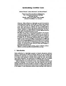
from the current waypoint to the waypoint in the chosen successor is activated. If in the successor state stopSign is set, the controller will cause the robot to stop when arriving at the successor waypoint. V. S IMULATIONS The approach described in this paper is demonstrated by simulations in MATLAB of different traffic scenarios using the actual RNDF and MDFs of the NQE. For this event, the RNDF contained 405 waypoints defining three areas, each of which had at least one MDF associated with it. Figure 6 depicts areas A and C which are the areas used for the following simulations.
(a) Area A
(b) Area C
Fig. 6: Close up of areas A and C of the NQE Since the focus of this paper is the planning and hybrid control rather than the atomic controllers driving the robot from one waypoint to the next, the robot is simulated as a fully actuated point robot that perfectly tracks the reference trajectory connecting two adjacent waypoints. More complex dynamics can be handled as done in [3], [9]. All behaviors seen in the following have been generated using the exact same behavior automaton and driving controller relating to the MDF. The different behaviors exhibited are due to the different sensor information gathered in the different scenarios. In the following figures, the robot is represented as a blue square whenever it is moving and as a red triangle when it stops. Waypoints are marked with a blue ‘+’ while waypoints that have a stop sign are marked with a blue ‘*’. If present, obstacles are represented by a magenta ‘X’ and other vehicles by different colored stars. Figures 7 and 8 depict area A where the mission is to repeatedly reach the checkpoints marked with red diamonds. Note that the leftmost waypoint in the middle horizontal road has a stop sign associated with it. Figure 7 shows snapshots of the behavior induced by encountering an obstacle and Fig. 8 shows the behavior when a road block is detected. Figure 9 depicts area C where there are two 4-way stops. In this area, two other vehicles are driving. Initially the robot enters the area (a), then it arrives at an intersection shortly after the green car stopped (b). The robot then stops until the green car has cleared the intersection and then resumes its course (c,d)
VI. C ONCLUSIONS AND F UTURE WORK
(a) moving towards checkpoint 2
(b) stopping due to obstacle
(c) moving after obstacle cleared
(d) stopping at stop sign
Fig. 7: Behavior while encountering an obstacle
This paper presents an automatic and correct by construction method for creating the system in charge of planning and control of a robot competing in the DARPA Urban Challenge. This approach allows the designer to specify the robot’s desired behavior by using a set of propositions and high level instructions rather than hand coding different automata, thus eliminating errors and reducing development time. Furthermore, when the robot encounters a blocked road or lane there is no need to replan the route since all such contingency plans are included in the automata. The final event contained 941 waypoints and over 9000 links. While the framework presented in this paper can easily handle problems of this size, extracting an explicit representation of the automaton is time and memory consuming and unnecessary. The automata can be represented symbolically and at each step the next state can be extracted. We intend to reimplement the synthesis and execution algorithms to allow symbolic operations which will enable us to generate the controller for the final event of the 2007 Urban Challenge. ACKNOWLEDGMENT The authors thank the Ben Franklin racing team as well as team Caltech for all their help and insights. R EFERENCES
(a) stopping due to obstacle
(b) timer timed out
(c) taking a different route
(d) block cleared
Fig. 8: Encountering a temporarily blocked road
(a) initial locations of cars
(b) both the robot and the green car stop
(c) the green car moves
(d) the robot moves
Fig. 9: 4-way stop behavior
[1] C. Belta, A. Bicchi, M. Egerstedt, E. Frazzoli, E. Klavins, and G. J. Pappas. Symbolic planning and control of robot motion: State of the art and grand challenges. Robotics and Automation Magazine, 14(1):61–70, 2007. [2] H. Choset, K. M. Lynch, S. Hutchinson, W. B. G. Kantor, L. E. Kavraki, and S. Thrun. Principles of Robot Motion: Theory, Algorithms, and Implementations. MIT Press, 2005. [3] D. C. Conner, H. Kress-Gazit, H. Choset, A. A. Rizzi, and G. J. Pappas. Valet parking without a valet. In IEEE/RSJ Int’l. Conf. on Intelligent Robots and Systems, San Diego, CA, October 2007. [4] DARPA. Urban challenge documentation. available online at http://www.darpa.mil/grandchallenge/rules.asp. [5] E. A. Emerson. Temporal and modal logic. In Handbook of theoretical computer science (vol. B): formal models and semantics, pages 995– 1072. MIT Press, Cambridge, MA, USA, 1990. [6] H. Kress-Gazit, G. E. Fainekos, and G. J. Pappas. From structured english to robot motion. In IEEE/RSJ Int’l. Conf. on Intelligent Robots and Systems, San Diego, CA, October 2007. [7] H. Kress-Gazit, G. E. Fainekos, and G. J. Pappas. Where’s waldo? sensor-based temporal logic motion planning. In IEEE International Conference on Robotics and Automation, pages 3116–3121, 2007. [8] S. M. LaValle. Planning Algorithms. Cambridge University Press, Cambridge, U.K., 2006. [9] S. R. Lindemann, I. I. Hussein, and S. M. LaValle. Realtime feedback control for nonholonomic mobile robots with obstacles. In IEEE Conference on Decision and Control, San Diego, CA, 2006. [10] N. Piterman, A. Pnueli, and Y. Sa’ar. Synthesis of Reactive(1) Designs. In VMCAI, pages 364–380, Charleston, SC, Jenuary 2006.