Automating the process of test derivation from SDL specifications G. v. Bochmann, A. Petrenko✬, O. Bellal, and S. Maguiraga Université de Montréal, CP. 6128, Succ. Centre-Ville, Montréal, H3C 3J7, Canada,
[email protected] ✬ CRIM,
Centre de Recherche Informatique de Montréal, 1801 Avenue McGill College, Suite 800, Montréal, H3A 2N4, Canada,
[email protected] In this paper, we present a set of automated tools for the development of conformance tests following a methodology based on a partial unfolding of a given SDL specification, describing the behavior of the system under test. The methodology relies on FSM-based test derivation methods which focus on the fault coverage aspect of testing. The tool kit offers to the test designer a number of options for achieving different levels of fault coverage. In particular, it provides support for partial specifications, grouped transitions and timers. The tests, which are generated in SDL or in TTCN must be completed by hand concerning certain aspects related to signal parameters, however, most of these adjustments are relatively straightforward and certain parts of the original SDL specification can be reused without change. We also report on our experience of using the tool kit for the development of a test suite for the ATM PNNI signalling protocol. 1. INTRODUCTION The specification of a system component or a protocol entity is the basis for any implementation or testing effort [1]. In order to (at least partially) automate these efforts, it is necessary that the specification exists in a form which is machine processable. Formal description techniques, such as SDL, have been developed with essentially two objectives: (1) encouraging the development of precise specifications which do not allow for any ambiguities, and (2) allowing the partial automation of the system development activities, such as the verification and evaluation of the system design (e.g. protocol specification); the implementation process, as existing (SDL) tools allow to produce implementation code [2]; and the test development process, in particular semi-automated development of test purposes, abstract test suites (written in TTCN, SDL or some ad hoc notation, possibly including sequences of API calls) and their validation and finally automatic translation into executable tests (Note: the automation of test suite development is most advanced for the FSM-related aspects of the specifications). While the use of formal specifications has many advantages, there are also some important shortcomings: (a) It takes time to build a formal specification. (b) The performance of the automatically generated implementation is less than optimal. (c) The aspect of PDU encoding is often difficult to express in the formal language. Coding routines written by hand may be used. (d) Concerning test development, the following observations can be made:
- Most tools only automate part of the test development process. - The test development process may be more difficult to be controlled by the test designer because certain decisions are taken by the tool (for instance the choice of a particular preamble, among several possibilities, for a given test case). - Most testing tools address the control flow (FSM) aspects only, and neglect the aspects related to interaction parameters. In this paper we concentrate on the problem of automatically deriving tests from a given specification in SDL. We present a tool kit which partially automates the derivation of a test suite from a specification and shortly describe its use for the development of a test suite for the ATM PNNI signalling protocol. Our approach to the design of testing tools, further discussed in Section 2, is based on the automatic extraction of a partially unfolded FSM model from the given SDL specification and the use of existing test derivation tools for partially specified FSM specifications. Using a pragmatic approach for the partial unfolding, the FSM model allows us to exploit the fault coverage guarantees provided by FSM-based test development methods (in an approximated manner) for the tests obtained from the SDL specification. We believe that our attention to fault coverage aspects, as compared to code (or transition) coverage considered by many other testing methods, leads to better test suites. Section 3 describes the proposed test development process and the tools we have developed for this purpose. Sections 4 and 5 discuss certain tool extensions which concern the efficient testing of groups of coherent transitions (such as erroneous or unexpected inputs) and the testing of the behavior of timers. Our experience with the application of the methodology to the ATM PNNI signalling protocol is described in Section 6, which is followed by the conclusions. 2. OUR APPROACH TO THE DESIGN OF TEST TOOLS FOR SDL The underlying model of an SDL specification is an Extended Finite State Machine (EFSM). Its most general form has not only internal (context) variables, but also input parameters such that a transition can only be executed if its enabling condition (usually in the form of a predicate depending on input parameters and state variables) is satisfied. It is a well-known difficult problem to derive a parameterized input sequence which either transfers an EFSM to a desired state or which distinguishes a pair of states. Compared with the classical FSM model, the EFSM model may give a very compressed behavioral description of the system, but at the same time, it is much less tractable for verification and test derivation purposes. If certain limiting assumptions are made about the form of the predicates and actions, the analysis of the behavior of the specification and systematic test selection remains decidable [3], but in general, in particular when the actions may include loops, the question of deciding which input parameters should be used in order to force the execution of a particular transition becomes undecidable, like the question of deciding the executability of a given branch of a program in software testing. Several researchers have proposed to use dataflow analysis for the systematic selection of test cases for EFSM, and therefore for SDL specifications. Dataflow analysis involves the input and output parameters and the additional state variables. By selecting appropriate test cases involving appropriate transitions, it is possible to satisfy the testing criteria that have been developed for software testing, such as "all definition-use pairs", etc. [4]. The aspect of fault detection is, however, not directly addressed within these approaches. An alternative approach is to view an EFSM as a compressed notation of an FSM. The intention behind this
approach is to retain the applicability of the FSM-based methods to generate tests. In this approach, at least three solutions exist to obtain a more tractable state-oriented specification: (1) to derive a pure FSM by ignoring all the extensions (parameters, predicates, and actions) to basic FSM model; (2) to unfold the EFSM into an FSM by expanding the values of the input parameters; (3) to extract an FSM by the partial unfolding of variables of enumerated types, while using enabling conditions as a part of the corresponding FSM inputs. The main drawback of the first option is that all the tests derived from the obtained FSM should be verified for executability. The second option, a straightforward unfolding of an EFSM, easily leads to an explosion of the number of states and inputs. In our work, we have decided to follow a compromise solution. The partial unfolding approach is based on the observation that most real protocols have not so many complicated predicates, a majority of transitions are not guarded by any predicate at all, while internal variables of enumerative types can easily be eliminated by unfolding (see also the normalization, as suggested in [5]). This observation has been reported by a number of researchers. It supports an optimistic view that “the worst usually does not come to the worst”. More precisely, we approximate the behavior of the SDL specification by an FSM (called an approximating machine), where an input of the FSM corresponds to a pair of an input signal and an enabling condition (if any), while states of the FSM mostly correspond to the control states of the SDL specification, except for unfolded states which are control states augmented with values of enumerative variables. In Section 3.2, we present the tool FEX (FSM extractor) which construct such an approximating machine from a given SDL specification. We believe that this approach has a number of attractive features: • the state/transition explosion is alleviated compared with “complete” unfolding; • the construction of an approximating machine can easily be automated; • FSM-based methods can be applied to generate tests with high fault coverage; • a good number of sequences derived from such an approximating machine usually remains executable with respect to the original SDL specification; • the number of non-executable sequences and, thus, of human interruptions needed to adjust them is controlled; • existing commercial SDL tools can be used to check the executability of sequences modified by hand; • once a major part of a test suite with a certain fault coverage (in terms of the FSM-based fault models) needs no adjustments, the final test suite is expected to have a high fault detection power, as well. Of course, the approach becomes less attractive for an EFSM with rather complicated enabling conditions, when most test sequences should be adjusted by hand. However, it never becomes inferior to the approach completely neglecting the predicates and parameters. 3. OUR TOOL KIT FOR TEST DERIVATION 3.1. The process of test derivation A number of different tools have been developed at the University of Montreal for partially automating the test development process. Most tools use an underlying FSM model, that is, the behavior of the system to be tested is expressed in terms of a number of states and inputs, and the outputs and state transitions produced by the arrival of a given input in a given state. These
tools are therefore useful for systems that can be characterized by FSM-oriented specifications, such as communication protocols. In the following we focus on a chain of tools for the development of test cases from SDL specifications, as shown in Figure 1. SDL Specification FEX FSM extractor FSM Specification Definition files
Test case (SDL skeleton)
TAG automatic test derivation
USER Completed Test Case (SDL)
T2CC (SDL to C translator)
SDT Validator
Validated Test Case (SDL) Executable Test Case (C code)
Figure 1: Test suite development from SDL specifications The diagram of Figure 1 shows in the middle column the description of objects leading from the formal specification in SDL of the component to be tested to the executable test cases written in C code. On the left and on the right are shown the tools that can be used during the test development process. The first tool, called FEX (FSM Extractor) extracts from the SDL specification a partial view of the behavior represented in the form of an FSM. At the same time, files containing SDL declarations of interactions (called "signals") and channels are created which can be later used for obtaining complete test cases written in SDL. The FEX tool generates an FSM transition for each branch of each SDL transition in the specification; thus each branch corresponding to a particular input and particular conditions of the input parameters gives rise to a separate transition (for each state of the specification). We note that the resulting FSM model is quite similar to the "test matrix" which is commonly used for the (manual) development of protocol conformance test suites. The TAG (Automatic Test Generation) tool [6] is a generic tool for test suite development based on FSM specifications. It accepts as input a partially specified, deterministic FSM and generates test cases according to the options provided by the test designer. The options include the following: (a) Automatic generation of a complete test suite with guaranteed coverage of output and transfer faults (assuming that the number of states of the implementation under test (IUT) is not larger than the number of states of the specification); (b) Generation of tests for a specific transition (corresponding to a given "test purpose") selected by the test designer; (c) The use of state identification sequences for checking transfer faults is optional; (d) Separate generation of test preambles, postambles and state identification sequences; (e) Generation of tests related to timers (setting, resetting and time-out transitions, further discussed in Section 5)
(f) Generation of tests for grouped transitions (corresponding to a single SDL transition having several starting states, or several input signals, further discussed in Section 4). It is important to note that the TAG tool supports several output formats for the generated test cases: (1) I/O sequences: This format is easy to read and relatively condensed. (2) SDL skeletons: The generated SDL skeletons represent test cases, preambles, postambles and state identification sequences. They are complete SDL procedures, except that the details concerning the signal parameters are not included. (Note: If the SDL signals of the specification have no parameters, the generated SDL skeletons are complete SDL procedures). (3) TTCN-MP skeletons: The generated skeletons represent test cases, preambles, postambles and state identification sequences. They are complete TTCN dynamic behavior trees, except that the details concerning the signal parameters are not included. The generated test suite (in SDL or in TTCN) must in general be completed by hand (see below) in order to add the information concerning the signal (interaction) parameters, that is the checking of the conditions to be satisfied by the input parameters and the determination of the parameter values of the output signals. The next development step shown in Figure 1 is the validation of the obtained test cases against the original SDL specification, using an existing SDL development environment. After this validation step, the test cases may be compiled into executable C code, thus resulting in executable test cases. An SDL-to-C translator developed at the University of Montreal has been enhanced with a facility for automatically generating PDU coding and decoding routines. It has also been extended to partially automate the variation of parameter values used by the test cases. This tool, described in Section 3.5, allows the test designer to control the automatic variation of interaction parameters for obtaining a repeated execution of a given test case with varying interaction parameters. In the case that the generated test cases should be obtained in the TTCN language, the TTCN output option of the TAG tool could be used. The resulting test cases should be completed by hand in a way similar to what is described above. In this case, it would be profitable to generate the definition files in TTCN-MP, however, this would require the automatic translation of the declarations from SDL to TTCN. 3.2. Generating an FSM model from an SDL specification: the FEX tool The FEX tool applies a normalization algorithm on a given SDL1 specification in order to extract an FSM model from it. One or more transitions in the generated FSM correspond to a given input at a given state in the SDL specification. This is due to the fact that the tool uses partial unfolding to preserve constraints on the values of message parameters. In addition, FEX generates additional files to be included in the SDL skeletons of test cases generated by TAG. They contain data type declarations, signal declarations, channel and signal route definitions and related information. The FSM format used by TAG and generated by FEX is simple and intuitive. It consists of four sections specifying the FSM states, inputs, outputs and transition lists. Input signals are usually parameterized as shown in Example 3.1, for input I2. In this case FEX generates several transitions for the parameterized input using partial unfolding of parameters. Each transition corresponds to a different value of the parameter as specified in the subsequent decision statement. In Example 3.1, two transitions are generated for input I2 at state S0;
1
We use a subset of SDL which allows the description of one-process specifications.
corresponding to values 0 and 1 of parameter n. TAG treats I2(n=0) and I2(n=1) as two different inputs. Example 3. 1 SDL specification: state S0; input I1; output O1; nextstate S1; input I2(n); decision n; (0): output O2; nextstate S2; (1): output O3; nextstate S3; enddecision; FSM transitions generated: S0 ?I1 !O1 >S1; S0 ?I2(n=0) !O2 >S2; S0 ?I2(n=1) !O3 >S3;
As mentioned in the introduction, TAG produces SDL skeletons of derived test cases which are completed manually by the test designer. The information present in the reference SDL specification related to input/output parameters can be very useful to the user in this sense. FEX carries this information and reproduces it in the FSM specification, which is then reproduced by TAG as comments in appropriate places in the generated SDL skeletons of test cases. This helps the test designer avoid referring to the SDL specification each time he wants to complete a test case. Example 3.2 shows how assignment statements and timer operations are gathered and reproduced for a corresponding transition. Assignment task p := 7; and timer setting set(now+100,T); are associated to the second transition. Example 3. 2 SDL specification: state S0; input I1; output O1; nextstate S1; input I2(n); decision n; (0): task p := 7; set(now+100,T); output O2(p); nextstate S2; (1): output O3; nextstate S3; enddecision; FSM transitions generated: S0 ?I1 !O1 >S1; S0 ?I2(n=0) !O2 >S2 {(p := 7), set(now+100,T)}; S0 ?I2(n=1) !O3 >S3;
The main process of the SDL specification may make calls to procedures. These have their own FSM part. It may also make several calls to the same procedure, however, recursive calls are not supported. FEX produces one global FSM for the entire specification. FSM parts of called procedures should be linked to the main process FSM. When FEX encounters a procedure call, it produces a transition to the start state of this procedure. It then generates all of its transitions. The states generated for a given procedure must be different for each call of the procedure. To avoid state name collision, FEX prefixes a procedure state name with two things: the name of the procedure (to avoid collision with state names of other procedures), and
a call number (to distinguish state names of different calls of the same procedure). For instance, p_2_S1 denotes state S1 of the second call of procedure p. The tool only accepts a single-process SDL specifications and does not support recursive procedures. Besides, some control aspects related to state variables cannot be captured and preserved in the process of FSM extraction. For instance, the iteration of some transitions expressed by a counter variable cannot be reflected in the generated FSM. Typically, another transition is triggered whenever the counter reaches a specified value, i.e. after a number of iterations on other transitions. The FSM transition which corresponds to this latter case contains the iteration information only in the form of a condition associated with the input which cannot be interpreted in the proper way by the TAG tool. Therefore the generated test case(s) for this transition do not contain the sequence of input/output corresponding to the iteration part. In such cases, the test designer should be able to add the necessary interactions to obtain executable test cases. An example is given in [7]. 3.3. Test derivation: the TAG tool TAG implements the so-called transition identification approach for test derivation from an FSM. In particular, to achieve a particular test purpose which is a certain transition to be tested, the following steps have to be performed: - bring the FSM from its initial state to the starting state of the transition under test using the shortest input sequence possible (called a preamble of the test case); - execute the transition and check the observed output; - check a tail state of the transition by observing its reaction to a pre-selected set of state identification sequences, which can verify the correctness of the tail state (a test body to achieve the test purpose); - apply an input sequence to return to the initial state of the FSM (a postamble of the test case). The user may specify a so-called homing sequence which is expected to take the FSM from any state back to the initial state. The set of all preambles is called a state cover; the set of sequences used to execute all specified transitions is called a transition cover. State identification sequences are input sequences which distinguish states by their output reactions. Some FSMs may have indistinguishable states for which there exists no sequence which tells them apart. If this is the case for the given FSM then the tool still produces test cases, however, certain transfer faults in implementations might not be detected. A reduced or minimal machine has no indistinguishable states, and the tool produces a test suite for such a machine with the guaranteed coverage of all output and transfer faults within the specified number of states. The tool, further described in [6], implements the so-called HSI method [8], [9] which is similar to the widely known W-method [10] in which a characterization set is used for state identification. However, the HSI-method uses a tuple of subsets of a W set for the identification of each state and can be applied to partially specified FSMs. The tool supports the following two modes of test derivation: - complete test derivation, when a test suite has to test all transitions specified in the given FSM (according to the HSI method); - selective test derivation, when a test case has to test a single transition given as a test purpose. Before starting the tool, the user must have a text file containing the FSM specification with suffix ".fsm’’. This file can be produced by transforming an SDL specification through the tool FEX, or directly by using a text editor. The FSM specification is required to be deterministic and initially connected, but it may be partially or completely specified.
An FSM description consists of six parts: (1) the state definitions, (2) the input definitions, (3) the output definitions, (4) the transition definitions, (5) the variable declaration and (6) the homing sequence definition; parts (5) and (6) are optional. The user may use keyword "homing’’ to give a sequence of input names as a homing sequence of the FSM specification, that is, it leads the FSM from any state to the initial state. The names in the homing sequence may be undefined input names. The principle is that TAG adds a postamble in a test case, if there is a postamble for a tail state, the postamble is used; otherwise, if the homing sequence is given, the homing sequence is used. If there is no postamble and no homing sequence is given, no postamble is included in the test case. The FSM specification is analyzed, the tool displays the related information, such as whether or not it is initially connected, it has indistinguishable states, equivalent states, and states with no postamble. If there are non-deterministic transitions in a certain state in a given specification, one among these non-deterministic transitions is kept in the compiled FSM and the others are ignored. Test derivation for an FSM with indistinguishable states is also possible, though some faults in these states might not be detected. In these two cases the tool will prompt a warning message. The tool derives preambles and postambles (if required) for all the states of a given machine. A transition cover is also generated when a complete generation of tests is chosen. To obtain a minimal characterization set for a given FSM, as well as minimal harmonized state identification sets, may be an NP-hard problem. The tool TAG uses, therefore, an heuristic solution attempting to obtain minimal HSI sets. As the experiments show this method constructs state identifiers in a nearly polynomial time [6]. The user may select just one sequence from a state identifier to confirm the tail state of a transition. We note that the TAG tool supports three different formats in which the tests can be generated. An easily readable mnemonic format in the form of I/O sequences, SDL skeletons and TTCN behavior tables. A complete example of the test case generated for a given transition of the INRES protocol is given in [7]. 3.4. Completing the generated test skeletons SDL skeletons of the generated test cases must be completed by the test designer with respect to the aspects: - to supply values for all output signal parameters, where needed; - to supply variables to store all input signal parameters, where needed; - to add decision statements after input statements in order to check parameter values, where needed; - to supply the necessary declarations of variables and associated type definitions. The type definitions can be imported from the original SDL protocol specification, however, the other three aspects must be written by the test designer for each specific test case. As an example, we consider second FSM transition of Example 3.3 above. Part of the SDL skeleton generated by TAG is shown below. We note that the test case specifies the behavior of the tester, therefore the inputs of the FSM specification become the outputs for the tester and vice versa. ... /* USER: make n = 0 */ output I2(/* USER: fill parameters */); nextstate wait_O2_in_S0; state wait_O2_in_S0; /* (p := 7), set(now+100,T) */
input O2; /* USER: Check parameters */ ...
Completed by the test designer, this part of the test case may look as follows. Note in particular the assignment statement (p := 7) is replaced by a decision statement which checks the assigned value of the parameter P of input O2. ... task n := 0; output I2(n); nextstate wait_for_O2_in_S0; state wait_for_O2_in_S0; input O2(P); decision P; (7): RETURN; (else): MACRO fail(’ param. of O2 expected to be 7’); return; enddecision; ...
Except for the handling of interaction parameters, the test case skeletons generated by TAG are complete SDL specifications, including all necessary BLOCK, CHANNEL and PROCESS definitions. A test suite is represented as an SDL process which contains the test preambles, state identification sequences and postambles as procedures. Each test case is also represented as a procedure calling, in order, the preamble, the transition under test, optionally the state identification sequence and the postamble. 3.5. Parameter variation One of the difficulties encountered during test design is the generation of different tests for the different values of input parameters to be tested. The Test Parameter Variation tool can be used to generate such tests with different representative valid and/or invalid values. It first generates additional representative values for each test parameter according to its declared type, and then generates tuples of test values possibly varying simultaneously the values of several test parameters. The scheme of variation can be specified by the test designer in the test script. The test designer is given the possibility to specify some or all of the representative valid and/or invalid values for a given test parameter; the Test Parameter Variation tool completes the lists of valid and invalid values, if left open by the test designer. Tuples of parameter values to be used in tests are output in files which are used by the generated code during test execution. Since it is impossible to test an implementation under test with all possible values of test parameters, a representative set of values has to be chosen. Both normal and abnormal situations should be applied to the IUT. Therefore test parameter values should include both representative valid and invalid values. In this respect, two kinds of problems are to be addressed. The first one is related to the generation of sets of representative values from determined data types; the second involves the organization of these sets of values in value tuples, which can be applied in a single execution of a test case. Most methods for value generation use the idea of dividing the set of values of a given data type into equivalence classes, where each equivalence class regroups values of the given type that are considered to lead to the same testing effect. One representative value is then chosen from each equivalence class. Equivalence classes are determined for invalid values as well. Some methods use the limit values in types to determine valid and invalid values. In contrast, other methods rely on the test designer’s intuition. We choose here a combination of these methods where valid and invalid values are automatically generated and/or determined by the test designer (see also [11], [12]). Values tuples are then automatically calculated, and the test
designer may suppress some of these value tuples or add others that he believes appropriate for testing based on his expertise. After the generation of the possible values (representative "normal" values and "invalid" values) for each parameter to be selected by a test case, it is important to determine which combination of values should be applied in a test run. If all parameter values are varied independently of one another, a combinatorial explosion of test runs could easily occur. Therefore the test designer should indicate which combination of parameter values should actually be used in the test runs. The problem here is to generate a set of combinations that cover all of the valid and invalid representative values. This is not straightforward because dependencies may exist between some of the parameters, for instance between a string (one parameter) and its length (another parameter). Moreover, a test designer may want to have some parameters varied in parallel and others in a dependent way. Three methods of value variation can be specified: variation in combination, in parallel, and free variation. 4. COHERENT TRANSITIONS RESULTING FROM SDL SPECIFICATIONS In spite of the fact that state/transition explosion does not usually occur when an approximating machine is derived from an SDL specification, the number of transitions specified in the obtained machine can yet be very high. As a result, the total length of tests derived by means of TAG tool could be quite big, as well. This often happens when a single transition of the given specification yields in the resulting machine multiple “similar” transitions having the same output. The basic idea is to test only one (or a few) transition among a set of similar ones. In the following, we first take a closer look at the source of multiple transitions and then we describe how these transitions could be handled, involving some pragmatic decisions, in order to further reduce the number of generated tests. First, it is well known that a single statement in SDL may be used to describe multiple transitions. For example, the fragment state * (s1, s2, s3); input i1, i2; output o; nextstate s4; corresponds to many transitions from all states, except s1, s2, s3, under input i1 or i2. Each of these transition has the same output o leads to the same next state s4. We call such a group of transitions convergent transitions. If the next state is specified as "-" (meaning to remain in the same state), then the statement describes the set of transitions which we call a group of looping transitions. In addition, the symbol "*" may be used to describe a set of inputs. Second, according to the SDL semantics, all unspecified inputs in a given state must be ignored (the so-called completeness assumption). Speaking formally, any approximating machine should therefore be completely specified by enumerating all transitions implied the completeness assumption. An exception could apparently be made for inputs representing primitives from an upper layer, as they are usually left undefined in standardizing documents. Extracting a finite state machine from any specification, the “ignored” inputs imply a number of looping transitions labeled with the dummy “null” output. The test designer may decide to test whether the (completeness assumption) [4] is correctly implemented by applying a limited number of inputs (PDU’s) in certain states, leaving the majority of the implied transitions untested.
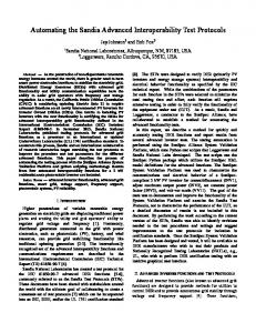
Finally, multiple transitions also result from unfolding the parameter values of input signals and/or the values of control state variables. Such groups of transitions are considered by the parameter variation tool described in Section 3.5, but are not considered in the following. In general, we call a group of convergent or looping transitions a group of coherent transitions. These groups can be distinguished according to the sets of starting states and/or the sets of inputs; all transitions of a group have the same output. The information about coherent transitions may either be deduced automatically from a given SDL specification or given by the test designer in the form of a list of coherent groups (in addition to the list of individual transitions). In our extended TAG tool, the following notation is used to specify coherent transitions. “E !I ?O > -“ represents a group of cycling transitions for the set of states E, labeled with all inputs of the set I and the output O. A similar notation “E !I ?O > S“ is used for convergent transitions. The sets E, I can be specified explicitly by enumeration; the expression “*\P” is used for the complement of P. The decision to test a single representative among convergent transitions is based on the following “fault-coupling” hypothesis. In particular, if a single transition has a fault then all coherent transitions in the group are faulty; all of them have a wrong output or/and wrong tail state. Testing just one among the group would be sufficient. Theoretically speaking, fault detection power of the resulting test suite may not always correspond to what is often called “complete fault coverage” [13]. However, deriving tests only for selected transitions gives a good tradeoff between the length of tests and the fault coverage. Again, it is up to the user of the tool to make a proper selection of transitions to be tested. Note that in the case of cycling transitions, not one, but at least two transitions should be selected. The reason is that, an implementation error may convert them into convergent transitions leading to the same state which, by chance, may have been chosen for testing the cycling transition of the specification. The extended TAG [14] performs such "selective" test generation. However, it does not take coherence into account for the generation of state identifiers; therefore the same state identifiers (if requested by the test designer) are used for complete or selective test derivation. 5. HANDLING TIMERS AND RELATED COUNTERS Error-recovery functions of communication protocols often rely on timers which invoke limited retransmission of PDU’s. At the expiration of a timer, a specific output is sent and the timer is restarted if the maximum number of retransmissions is not yet attained. If the maximum number is reached, usually a different transition with a different output is taken, for example, to release the current connection. Certain received input messages may stop a running timer. The classical model of an FSM has no notion of time, yet it is quite common to use, in stateoriented specifications, a dummy input T to represent a silent time period which leads to the expiration of time T. To model the behavior triggered by timers and related counters, one typically augments FSM transitions between (control) states by internal actions “start T”, “stop T” and adds transitions guarded by timer expirations (time-outs), as shown in Figure 2.
T&C=max/o2
r
T&C